EP2954963B1 - Fraise à face de coupe à deux phases - Google Patents
Fraise à face de coupe à deux phases Download PDFInfo
- Publication number
- EP2954963B1 EP2954963B1 EP14172324.7A EP14172324A EP2954963B1 EP 2954963 B1 EP2954963 B1 EP 2954963B1 EP 14172324 A EP14172324 A EP 14172324A EP 2954963 B1 EP2954963 B1 EP 2954963B1
- Authority
- EP
- European Patent Office
- Prior art keywords
- partial
- milling cutter
- rake face
- partial rake
- cutting edge
- Prior art date
- Legal status (The legal status is an assumption and is not a legal conclusion. Google has not performed a legal analysis and makes no representation as to the accuracy of the status listed.)
- Active
Links
Images



Classifications
-
- B—PERFORMING OPERATIONS; TRANSPORTING
- B23—MACHINE TOOLS; METAL-WORKING NOT OTHERWISE PROVIDED FOR
- B23C—MILLING
- B23C5/00—Milling-cutters
- B23C5/02—Milling-cutters characterised by the shape of the cutter
- B23C5/10—Shank-type cutters, i.e. with an integral shaft
-
- B—PERFORMING OPERATIONS; TRANSPORTING
- B23—MACHINE TOOLS; METAL-WORKING NOT OTHERWISE PROVIDED FOR
- B23C—MILLING
- B23C2210/00—Details of milling cutters
- B23C2210/12—Cross section of the cutting edge
-
- B—PERFORMING OPERATIONS; TRANSPORTING
- B23—MACHINE TOOLS; METAL-WORKING NOT OTHERWISE PROVIDED FOR
- B23C—MILLING
- B23C2210/00—Details of milling cutters
- B23C2210/12—Cross section of the cutting edge
- B23C2210/123—Bevelled cutting edges
-
- B—PERFORMING OPERATIONS; TRANSPORTING
- B23—MACHINE TOOLS; METAL-WORKING NOT OTHERWISE PROVIDED FOR
- B23C—MILLING
- B23C2210/00—Details of milling cutters
- B23C2210/54—Configuration of the cutting part
-
- B—PERFORMING OPERATIONS; TRANSPORTING
- B23—MACHINE TOOLS; METAL-WORKING NOT OTHERWISE PROVIDED FOR
- B23C—MILLING
- B23C2222/00—Materials of tools or workpieces composed of metals, alloys or metal matrices
- B23C2222/04—Aluminium
-
- B—PERFORMING OPERATIONS; TRANSPORTING
- B23—MACHINE TOOLS; METAL-WORKING NOT OTHERWISE PROVIDED FOR
- B23C—MILLING
- B23C2226/00—Materials of tools or workpieces not comprising a metal
- B23C2226/27—Composites, e.g. fibre reinforced composites
-
- B—PERFORMING OPERATIONS; TRANSPORTING
- B23—MACHINE TOOLS; METAL-WORKING NOT OTHERWISE PROVIDED FOR
- B23C—MILLING
- B23C2250/00—Compensating adverse effects during milling
- B23C2250/12—Cooling and lubrication
Definitions
- the invention relates to a milling cutter for use in a rotating tool chuck of a flat bed cutter according to the preamble of independent claim 1.
- CNC-controlled flatbed cutters provided for such processes have a gantry design and thus guide a tool spindle in an x- and in a ⁇ -axis along a desired cutting line on the plate to be cut.
- the tool infeed takes place vertically in the z-axis, usually implemented by moving the tool spindle in a translatory manner.
- One or more of the axes driven on the tool side can alternatively also be driven on the workpiece side, e.g. over the slide clamping the plate so that e.g. a stand, console, cross bed, table or portal construction is realized.
- a milling cutter, in particular an end mill, clamped into the chuck of the tool spindle using a cylindrical shank or another type of tool holder has at least one cutting edge with a flute, which is in particular helical, alternatively also straight-toothed, in particular right-hand twisted, alternatively also left-hand twist, circumferentially on the cutting part of the milling cutter - in Hereinafter referred to as the head part - extends.
- the head part has an in particular cylindrical, alternatively also conical or custom-made shape.
- the method of peripheral milling is used at least mainly. It is known to the person skilled in the art that the milling cutter can also be expanded to include face cutting edges for vertical plunge into the plate can. This avoids having to start the cutting process from the edge of the plate.
- the milling cutter With high-speed machining, the milling cutter is very heavily loaded by the particularly high speeds and the high feed speeds also cause a high metal removal rate.
- the supply of coolant or lubricant is therefore of great importance when designing the corresponding processes. Due to the high circumferential speeds at the cutter cutting edge, however, it is made difficult, among other things, because of the enormous centrifugal forces that result.
- a built-up edge is created by highly solidified bonding of the machined material to the tool edge as a result of pressure welding processes. When these bonds break off, parts of the tool cutting edge also shear off, so that the service life is shortened by this wear and tear.
- Breakouts due to a cutting edge that is too thin in terms of design also reduce the service life.
- large cutting forces cause cutting edge and / or corner breakouts with small wedge angles selected.
- Larger chosen wedge angles do guarantee a stabilization of the cutting edge against chipping, however, due to the obtuse-angled material separation during chip formation, the cutting properties are impaired.
- the DE 10 2006 037 906 A1 shows a milling tool which - similar to the milling cutter of the present invention - is single-edged and designed for speeds of 60,000 revolutions per minute or more.
- the cylindrical base body carrying the milling cutter is designed so that the center of gravity at every point along its longitudinal axis in the The axis of rotation comes to rest and the imbalance is thus practically reduced to zero.
- the JP 2005 297108 A shows an end mill which, however, is designed for milling workpieces based on iron and aluminum at significantly lower speeds and which enables the cutting resistance to be reduced using a chip pocket for ejecting the chips.
- This end mill has 2 to 10 cutting edges.
- a rake face When viewed in a cross section perpendicular to the axis of rotation, a rake face has two outer rake angles. The first external rake angle is set to 0 ° to 25 ° and the second to 5 ° to 40 °. The first rake angle is smaller than the second rake angle.
- Milling cutters known from the prior art for processing aluminum often have a polished flute in order to ensure better chip evacuation due to the reduced friction.
- the disadvantage of a completely polished flute is that the cooling lubricant also hardly sticks to the surface. This significantly reduces the cooling lubricant supply at the point of heat development and the formation of a built-up edge is increasingly likely.
- the subject matter according to the invention relates to a cutting machine milling cutter for use in a rotating cutting tool of a cutting machine, designed and precisely provided for milling a plate, in particular a composite panel made from material based on wood, plastic and / or a non-ferrous metal, in particular from acrylic glass / plexiglass (polymethyl methacrylate), PET (polyethylene terephthalate) and / or aluminum, in particular from Dibond® (aluminum-polyethylene composite panels ) or MDF (medium-density fibreboard).
- a cutting machine milling cutter for use in a rotating cutting tool of a cutting machine, designed and precisely provided for milling a plate, in particular a composite panel made from material based on wood, plastic and / or a non-ferrous metal, in particular from acrylic glass / plexiglass (polymethyl methacrylate), PET (polyethylene terephthalate) and / or aluminum, in particular from Dibond® (aluminum-polyethylene composite panels
- the milling cutter is intended for use in the context of an automatic milling mode, in which the rotating milling cutter is immersed in a feed direction along the plate in a program-controlled manner by the milling machine or is guided completely through it.
- the milling cutter is designed for high-speed milling in the speed range from 20,000 rpm to 100,000 rpm, in particular for a speed of around 50,000 rpm and for feed speeds of between 2.4 m / min and 120 m / min.
- the first partial chip surface has a flat surface and therefore a continuous partial chip angle ( ⁇ 1 ) of between 18 ° and 30 °, which is 4 ° to 8 °, in particular 5 ° to 7 ° and in particular about 6 ° smaller is than the partial rake angle ( ⁇ 2 ) of between 22 ° and 38 ° of the second partial rake face.
- This gradation of the rake face creates a larger wedge angle and thus stabilizes the cutting edge against chipping during the milling process and improves cutting properties during chip formation.
- the first partial rake angle ( ⁇ 1 ) is preferably between 20 ° and 28 °, in particular between 22 ° and 26 °, in particular around 24 °, and the second partial rake angle ( ⁇ 2 ) between 24 ° and 36 °, in particular between 26 ° and 34 °, in particular between 28 ° and 32 ° and in particular about 30 °.
- the first chip surface also has a polished surface and the second chip surface has an unpolished surface.
- the lubricant which has a positive effect on the milling process, can be used on the unpolished Because of the higher roughness, the surface of the second chip surface adheres better than on the polished surface of the first chip surface.
- the fact that the second chip surface is unpolished - and can therefore be lubricated - prevents a tough material to be machined from sticking to the cutting edge and thus preventing a built-up cutting edge.
- the milling parameters are optimized, for example a greater infeed depth and thus a higher material removal rate and the applicability to several materials, especially composite materials.
- a surface is regularly considered polished when it is shiny and unpolished when it is matt.
- a range of mean surface roughness R a of between 0.05 ⁇ m and 0.2 ⁇ m and / or the range of mean roughness depth R z of between 0.2 ⁇ m and 1 ⁇ m are defined as the polished surface.
- a range of mean surface roughness R a of between 0.2 ⁇ m and 0.4 ⁇ m and / or the range of mean roughness depth R z of between 0.8 ⁇ m and 1.4 ⁇ m are defined as the unpolished surface.
- the second partial chip surface can take an arched course.
- the partial rake angle of the second partial chip surface ( ⁇ 2 ) can therefore be measured at the transition from the first to the second partial chip surface, tangentially at the beginning of the second partial chip surface.
- the width b of the first partial chip surface perpendicular to the cutting edge is between 0.01 mm and 0.2 mm, in particular between 0.04 mm and 0.12 mm.
- the diameter of the cutting head part ie the rotation diameter of the cutting edge, is between 1 mm and 10 mm, in particular 2 mm, 3 mm, 4 mm, 5 mm, 6 mm or 8 mm.
- the milling cutter has a bevel s up to 0.1 mm long, in particular 0.05 mm long, at the tip of a cutting edge on the circumference in the plane of the first rake face in order to again prevent breakouts.
- FIG. 1 a cutting tool in the form of an end mill shown in clockwise form.
- the end mill 1 comprises a shank 2 and a head part 3 which has a right-hand helical cutting edge.
- the cutting surface of the milling cutter is divided into a first partial cutting surface 4 and a second partial cutting surface 5.
- the end face of the milling cutter is in turn divided into a stepped part 6 and a free part 7.
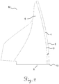
- Figure 2 shows part of the head part 3 in a side view with a plan view of the two partial chip surfaces 4 and 5, the plane of the paper corresponding to the tool reference plane.
- the first partial chip surface 4 is separated from the second partial chip surface 5 via the partial chip surface transition edge 9.
- the cutting edge 8 On the circumference of the head part 3 is the cutting edge 8, which in Figure 2 is shown curved due to the twist and due to the perspective.
- the first chip surface 4 has a polished surface and the second chip surface 5 has an unpolished surface, which is evident in the Figures 2 and 3 is indicated by hatching.
- FIG. 2 shows Figure 3 a bevel 10 with its width s on the milling cutter tip.
- This chamfer 10 connects the cutting edge 8 with the stepped partial end face 6.
- the width b of the first partial chip surface 4 is defined in each case perpendicular to the cutting edge 8 and to the partial chip surface transition edge 9.
- a polished surface of the first partial chip surface 4 characterized by hatching.
- FIG 4 a top view of a section of the end face of the milling cutter containing the cutting edge in the tool orthogonal plane is shown.
- the milling cutter 1 rotates about its axis of rotation M and has a cutting edge diameter 12.
- the free surface 11 of the milling cutter 1 can optionally be subdivided into a plurality of partial free surfaces, which are subject to several partial clearance angles.
- the first partial rake face 4 has a first partial rake angle ⁇ 1 and the second partial rake face 5 has a partial rake angle ⁇ 2 .
- the first partial rake angle ⁇ 1 of the partial chip surface 4 is maintained, whereas the second partial rake angle ⁇ 2 can be measured tangentially directly after the partial chip surface transition edge 9 at the beginning of the second partial chip surface 5.
- the second partial chip surface 5 preferably takes a curved course in order to thus form the chip flute via which the chips are transported away.
- the bevel 10 on the milling cutter tip extends in terms of area preferably orthogonally to the tool reference plane and parallel to the tool cutting edge plane.
- the shape of the bevel 10 is flat in this case, but alternatively it can also be curved, for example.
- Figure 5 illustrates the entire face of the milling cutter from above, with the paper plane as in Figure 4 corresponds to the tool orthogonal plane.
- the diameter 13 of the shank 2 of the milling cutter is greater than the diameter 12 of the head part 3 of the milling cutter.
Landscapes
- Engineering & Computer Science (AREA)
- Mechanical Engineering (AREA)
- Milling Processes (AREA)
Claims (9)
- Fraise (1) pour le fraisage à grande vitesse à des vitesses de fonctionnement comprises entre 20 000 tr/min et 100 000 tr/min et des vitesses d'avance comprises entre 2,4 m/min et 120 m/min, et destinée à être serrée dans l'outil d'une table de découpe à plat prévue précisément pour la découpe de carton, de bois, de plastique, d'aluminium et de panneaux composites de ces matériaux, présentant :• une queue (2) pour le serrage de la fraise (1),• une partie tête (3) attenante à la queue (2) avec exactement une lame située sur la circonférence, dans laquelle▪ la lame présente une face de coupe et▪ la face de coupe présente au moins une première face de coupe partielle (4) partant de l'arête de coupe (8) et une deuxième face de coupe partielle (5) faisant suite à la première face de coupe partielle,caractérisée en ce que• la première face de coupe partielle (4)▪ présente un premier angle de coupe partiel (γ1) compris entre 18° et 30°,▪ conserve cet angle de coupe partiel (γ1) jusqu'au début de la deuxième face de coupe partielle (5), et▪ présente une surface polie, et• la deuxième face de coupe partielle (5)▪ présente un deuxième angle de coupe partiel (γ2) compris entre 22° et 38°, et▪ présente une surface non polie,
dans laquelle le deuxième angle de coupe partiel (γ2) est supérieur au premier angle de coupe partiel (γ1) de 4° à 8°, en particulier de 5° à 7° et en particulier de 6°. - Fraise selon la revendication 1,
caractérisée en ce que
le premier angle de coupe partiel (γ1) est compris entre 20° et 28°, en particulier entre 22° et 26°, en particulier est d'environ 24°, et le deuxième angle de coupe partiel (γ2) est compris entre 24° et 36°, en particulier entre 26° et 34°, en particulier entre 28° et 32°, et est en particulier d'environ 30°. - Fraise selon l'une des revendications précédentes,
caractérisée en ce que
la première face de coupe partielle (4) présente une rugosité de surface moyenne Ra comprise entre 0,05 µm et 0,2 µm et/ou une profondeur de rugosité moyenne Rz comprise entre 0,2 µm et 1 µm, et la deuxième face de coupe partielle (5) présente une rugosité de surface moyenne Ra comprise entre 0,2 µm et 0,4 µm et/ou une profondeur de rugosité moyenne Rz comprise entre 0,8 µm et 1,4 µm. - Fraise selon l'une des revendications précédentes,
caractérisée en ce que
la première face de coupe partielle (4) présente une largeur (b) perpendiculairement à l'arête de coupe comprise entre 0,01 mm et 0,2 mm, en particulier entre 0,04 mm et 0,12 mm. - Fraise selon l'une des revendications précédentes,
caractérisée en ce que
la deuxième face de coupe partielle (5) présente une convexité. - Fraise selon l'une des revendications précédentes,
caractérisée en ce que
l'arête de coupe (8) a un diamètre de rotation (12) compris entre 1 mm et 10 mm, en particulier de 2 mm, 3 mm, 4 mm, 5 mm, 6 mm ou 8 mm. - Fraise selon l'une des revendications précédentes,
caractérisée en ce que
l'arête de coupe (8) de la lame s'étend en hélice le long d'une surface latérale qui est concentrique à l'axe de rotation (M) de l'outil, la surface latérale étant réalisée en particulier sous la forme d'une surface latérale cylindrique. - Fraise selon l'une des revendications précédentes,
caractérisée en ce que
la fraise (1) est spécialement conçue pour le fraisage de panneaux d'aluminium, de composite aluminium-polyéthylène, de fibre de bois, de mousse rigide, d'acrylique et de polyéthylène téréphtalate. - Fraise selon l'une des revendications précédentes,
caractérisée en ce que
la pointe de la lame présente sur sa périphérie un chanfrein (10) s'étendant dans le plan de la première face de coupe, et que ce chanfrein a une longueur (s) pouvant atteindre 0,1 mm, en particulier de 0,05 mm.
Priority Applications (2)
| Application Number | Priority Date | Filing Date | Title |
|---|---|---|---|
| EP14172324.7A EP2954963B1 (fr) | 2014-06-13 | 2014-06-13 | Fraise à face de coupe à deux phases |
| ES14172324T ES2833047T3 (es) | 2014-06-13 | 2014-06-13 | Fresa con superficie de desprendimiento de dos fases |
Applications Claiming Priority (1)
| Application Number | Priority Date | Filing Date | Title |
|---|---|---|---|
| EP14172324.7A EP2954963B1 (fr) | 2014-06-13 | 2014-06-13 | Fraise à face de coupe à deux phases |
Publications (2)
| Publication Number | Publication Date |
|---|---|
| EP2954963A1 EP2954963A1 (fr) | 2015-12-16 |
| EP2954963B1 true EP2954963B1 (fr) | 2020-09-16 |
Family
ID=50933070
Family Applications (1)
| Application Number | Title | Priority Date | Filing Date |
|---|---|---|---|
| EP14172324.7A Active EP2954963B1 (fr) | 2014-06-13 | 2014-06-13 | Fraise à face de coupe à deux phases |
Country Status (2)
| Country | Link |
|---|---|
| EP (1) | EP2954963B1 (fr) |
| ES (1) | ES2833047T3 (fr) |
Families Citing this family (1)
| Publication number | Priority date | Publication date | Assignee | Title |
|---|---|---|---|---|
| DE102016116279A1 (de) | 2016-08-31 | 2018-03-01 | Datron Ag | Einschneidiges Fräswerkzeug |
Citations (1)
| Publication number | Priority date | Publication date | Assignee | Title |
|---|---|---|---|---|
| DE102006037906A1 (de) * | 2005-08-11 | 2007-02-15 | Datron-Electronic Gmbh | Fräswerkzeug und Verfahren zu seiner Herstellung |
Family Cites Families (5)
| Publication number | Priority date | Publication date | Assignee | Title |
|---|---|---|---|---|
| US3003224A (en) * | 1958-02-06 | 1961-10-10 | Weldon Tool Co | Cutting tool |
| JP3739591B2 (ja) * | 1999-04-05 | 2006-01-25 | 三菱マテリアル株式会社 | ソリッドエンドミル |
| DE10225481A1 (de) * | 2002-06-10 | 2003-12-18 | Sandvik Ab | Fräser mit Wiper-Radius |
| JP2005297108A (ja) * | 2004-04-09 | 2005-10-27 | Nachi Fujikoshi Corp | エンドミル |
| US7588396B2 (en) * | 2007-03-09 | 2009-09-15 | Berkshire Precision Tool, Llc | End mill |
-
2014
- 2014-06-13 ES ES14172324T patent/ES2833047T3/es active Active
- 2014-06-13 EP EP14172324.7A patent/EP2954963B1/fr active Active
Patent Citations (1)
| Publication number | Priority date | Publication date | Assignee | Title |
|---|---|---|---|---|
| DE102006037906A1 (de) * | 2005-08-11 | 2007-02-15 | Datron-Electronic Gmbh | Fräswerkzeug und Verfahren zu seiner Herstellung |
Also Published As
| Publication number | Publication date |
|---|---|
| EP2954963A1 (fr) | 2015-12-16 |
| ES2833047T3 (es) | 2021-06-14 |
Similar Documents
| Publication | Publication Date | Title |
|---|---|---|
| DE112011102803B4 (de) | Stirnfräs-/Bohr-/Aufreib-Kombinationsschneidwerkzeug und Verfahren | |
| DE102015112417B4 (de) | Rotierendes Schneidwerkzeug mit nachschleifbaren Schneideinsätzen | |
| EP3356071B1 (fr) | Outil de fraisage de finition, en particulier fraise à queue | |
| EP0937528A1 (fr) | Alésoir et sa méthode de production | |
| DE3742942C1 (en) | Milling tool for roughing and smoothing workpieces | |
| DE102016102651A1 (de) | Vorrichtung und Verfahren zur spanenden Bearbeitung eines rotierenden Werkstücks | |
| WO2018000009A1 (fr) | Outil de machine à percer | |
| DE3844338A1 (de) | Verfahren und vorrichtung zum bearbeiten von werkstuecken aus langspaenigem material | |
| WO2008055489A2 (fr) | Dispositif d'usinage de pièce par enlèvement de matière | |
| DE102013002730A1 (de) | Fräswerkzeug zum Schruppen und Schlichten von Werkstücken | |
| WO2019145208A1 (fr) | Outil de fraisage | |
| EP3132875A1 (fr) | Outil de fraisage | |
| DE102016222595B4 (de) | Verfahren und Fräswerkzeug zur Herstellung einer Kavität in einem Werkstück für die Aufnahme einer Zentrierspitze | |
| EP1901873A1 (fr) | Procede d'usinage de vilebrequins par enlevement de copeaux et dispositif permettant la mise en oeuvre dudit procede | |
| EP2347844B1 (fr) | Procédé de rectification d'un logement de centrage | |
| DE102012212440B4 (de) | Bohrwerkzeug insbesondere zur Bearbeitung von Bauteilen aus einer Titanlegierung sowie Verfahren zur Bearbeitung eines solchen Bauteils | |
| DD272618A1 (de) | Drehwerkzeuge zur aussenbearbeitung rotationssymmetrischer werkstuecke | |
| EP3031560A1 (fr) | Outil d'usinage et plaque de coupe pour l'outil d'usinage | |
| EP3423225A1 (fr) | Plaquette de coupe | |
| EP2954963A1 (fr) | Fraise à face de coupe à deux phases | |
| EP3507044B1 (fr) | Outil de fraisage à un seul tranchant | |
| EP3870384A1 (fr) | Foret étagé | |
| DE202013101404U1 (de) | Bohrwerkzeug | |
| DE102004044372B4 (de) | Werkzeug zum Bearbeiten von Radreifenprofilen | |
| CH705289A2 (de) | Metallrohr. |
Legal Events
| Date | Code | Title | Description |
|---|---|---|---|
| PUAI | Public reference made under article 153(3) epc to a published international application that has entered the european phase |
Free format text: ORIGINAL CODE: 0009012 |
|
| 17P | Request for examination filed |
Effective date: 20150811 |
|
| AK | Designated contracting states |
Kind code of ref document: A1 Designated state(s): AL AT BE BG CH CY CZ DE DK EE ES FI FR GB GR HR HU IE IS IT LI LT LU LV MC MK MT NL NO PL PT RO RS SE SI SK SM TR |
|
| AX | Request for extension of the european patent |
Extension state: BA ME |
|
| STAA | Information on the status of an ep patent application or granted ep patent |
Free format text: STATUS: EXAMINATION IS IN PROGRESS |
|
| 17Q | First examination report despatched |
Effective date: 20180418 |
|
| GRAP | Despatch of communication of intention to grant a patent |
Free format text: ORIGINAL CODE: EPIDOSNIGR1 |
|
| STAA | Information on the status of an ep patent application or granted ep patent |
Free format text: STATUS: GRANT OF PATENT IS INTENDED |
|
| INTG | Intention to grant announced |
Effective date: 20200424 |
|
| GRAS | Grant fee paid |
Free format text: ORIGINAL CODE: EPIDOSNIGR3 |
|
| GRAA | (expected) grant |
Free format text: ORIGINAL CODE: 0009210 |
|
| STAA | Information on the status of an ep patent application or granted ep patent |
Free format text: STATUS: THE PATENT HAS BEEN GRANTED |
|
| AK | Designated contracting states |
Kind code of ref document: B1 Designated state(s): AL AT BE BG CH CY CZ DE DK EE ES FI FR GB GR HR HU IE IS IT LI LT LU LV MC MK MT NL NO PL PT RO RS SE SI SK SM TR |
|
| REG | Reference to a national code |
Ref country code: GB Ref legal event code: FG4D Free format text: NOT ENGLISH |
|
| REG | Reference to a national code |
Ref country code: CH Ref legal event code: EP |
|
| REG | Reference to a national code |
Ref country code: DE Ref legal event code: R096 Ref document number: 502014014755 Country of ref document: DE |
|
| REG | Reference to a national code |
Ref country code: IE Ref legal event code: FG4D Free format text: LANGUAGE OF EP DOCUMENT: GERMAN |
|
| REG | Reference to a national code |
Ref country code: AT Ref legal event code: REF Ref document number: 1313700 Country of ref document: AT Kind code of ref document: T Effective date: 20201015 |
|
| REG | Reference to a national code |
Ref country code: CH Ref legal event code: NV Representative=s name: KAMINSKI HARMANN PATENTANWAELTE AG, LI |
|
| REG | Reference to a national code |
Ref country code: NL Ref legal event code: FP |
|
| PG25 | Lapsed in a contracting state [announced via postgrant information from national office to epo] |
Ref country code: HR Free format text: LAPSE BECAUSE OF FAILURE TO SUBMIT A TRANSLATION OF THE DESCRIPTION OR TO PAY THE FEE WITHIN THE PRESCRIBED TIME-LIMIT Effective date: 20200916 Ref country code: NO Free format text: LAPSE BECAUSE OF FAILURE TO SUBMIT A TRANSLATION OF THE DESCRIPTION OR TO PAY THE FEE WITHIN THE PRESCRIBED TIME-LIMIT Effective date: 20201216 Ref country code: GR Free format text: LAPSE BECAUSE OF FAILURE TO SUBMIT A TRANSLATION OF THE DESCRIPTION OR TO PAY THE FEE WITHIN THE PRESCRIBED TIME-LIMIT Effective date: 20201217 Ref country code: SE Free format text: LAPSE BECAUSE OF FAILURE TO SUBMIT A TRANSLATION OF THE DESCRIPTION OR TO PAY THE FEE WITHIN THE PRESCRIBED TIME-LIMIT Effective date: 20200916 Ref country code: FI Free format text: LAPSE BECAUSE OF FAILURE TO SUBMIT A TRANSLATION OF THE DESCRIPTION OR TO PAY THE FEE WITHIN THE PRESCRIBED TIME-LIMIT Effective date: 20200916 Ref country code: BG Free format text: LAPSE BECAUSE OF FAILURE TO SUBMIT A TRANSLATION OF THE DESCRIPTION OR TO PAY THE FEE WITHIN THE PRESCRIBED TIME-LIMIT Effective date: 20201216 |
|
| PG25 | Lapsed in a contracting state [announced via postgrant information from national office to epo] |
Ref country code: LV Free format text: LAPSE BECAUSE OF FAILURE TO SUBMIT A TRANSLATION OF THE DESCRIPTION OR TO PAY THE FEE WITHIN THE PRESCRIBED TIME-LIMIT Effective date: 20200916 Ref country code: RS Free format text: LAPSE BECAUSE OF FAILURE TO SUBMIT A TRANSLATION OF THE DESCRIPTION OR TO PAY THE FEE WITHIN THE PRESCRIBED TIME-LIMIT Effective date: 20200916 |
|
| REG | Reference to a national code |
Ref country code: LT Ref legal event code: MG4D |
|
| PG25 | Lapsed in a contracting state [announced via postgrant information from national office to epo] |
Ref country code: CZ Free format text: LAPSE BECAUSE OF FAILURE TO SUBMIT A TRANSLATION OF THE DESCRIPTION OR TO PAY THE FEE WITHIN THE PRESCRIBED TIME-LIMIT Effective date: 20200916 Ref country code: EE Free format text: LAPSE BECAUSE OF FAILURE TO SUBMIT A TRANSLATION OF THE DESCRIPTION OR TO PAY THE FEE WITHIN THE PRESCRIBED TIME-LIMIT Effective date: 20200916 Ref country code: SM Free format text: LAPSE BECAUSE OF FAILURE TO SUBMIT A TRANSLATION OF THE DESCRIPTION OR TO PAY THE FEE WITHIN THE PRESCRIBED TIME-LIMIT Effective date: 20200916 Ref country code: RO Free format text: LAPSE BECAUSE OF FAILURE TO SUBMIT A TRANSLATION OF THE DESCRIPTION OR TO PAY THE FEE WITHIN THE PRESCRIBED TIME-LIMIT Effective date: 20200916 Ref country code: LT Free format text: LAPSE BECAUSE OF FAILURE TO SUBMIT A TRANSLATION OF THE DESCRIPTION OR TO PAY THE FEE WITHIN THE PRESCRIBED TIME-LIMIT Effective date: 20200916 Ref country code: PT Free format text: LAPSE BECAUSE OF FAILURE TO SUBMIT A TRANSLATION OF THE DESCRIPTION OR TO PAY THE FEE WITHIN THE PRESCRIBED TIME-LIMIT Effective date: 20210118 |
|
| PG25 | Lapsed in a contracting state [announced via postgrant information from national office to epo] |
Ref country code: AL Free format text: LAPSE BECAUSE OF FAILURE TO SUBMIT A TRANSLATION OF THE DESCRIPTION OR TO PAY THE FEE WITHIN THE PRESCRIBED TIME-LIMIT Effective date: 20200916 Ref country code: IS Free format text: LAPSE BECAUSE OF FAILURE TO SUBMIT A TRANSLATION OF THE DESCRIPTION OR TO PAY THE FEE WITHIN THE PRESCRIBED TIME-LIMIT Effective date: 20210116 Ref country code: PL Free format text: LAPSE BECAUSE OF FAILURE TO SUBMIT A TRANSLATION OF THE DESCRIPTION OR TO PAY THE FEE WITHIN THE PRESCRIBED TIME-LIMIT Effective date: 20200916 |
|
| REG | Reference to a national code |
Ref country code: ES Ref legal event code: FG2A Ref document number: 2833047 Country of ref document: ES Kind code of ref document: T3 Effective date: 20210614 |
|
| REG | Reference to a national code |
Ref country code: DE Ref legal event code: R097 Ref document number: 502014014755 Country of ref document: DE |
|
| PG25 | Lapsed in a contracting state [announced via postgrant information from national office to epo] |
Ref country code: SK Free format text: LAPSE BECAUSE OF FAILURE TO SUBMIT A TRANSLATION OF THE DESCRIPTION OR TO PAY THE FEE WITHIN THE PRESCRIBED TIME-LIMIT Effective date: 20200916 |
|
| PLBE | No opposition filed within time limit |
Free format text: ORIGINAL CODE: 0009261 |
|
| STAA | Information on the status of an ep patent application or granted ep patent |
Free format text: STATUS: NO OPPOSITION FILED WITHIN TIME LIMIT |
|
| 26N | No opposition filed |
Effective date: 20210617 |
|
| PG25 | Lapsed in a contracting state [announced via postgrant information from national office to epo] |
Ref country code: DK Free format text: LAPSE BECAUSE OF FAILURE TO SUBMIT A TRANSLATION OF THE DESCRIPTION OR TO PAY THE FEE WITHIN THE PRESCRIBED TIME-LIMIT Effective date: 20200916 Ref country code: SI Free format text: LAPSE BECAUSE OF FAILURE TO SUBMIT A TRANSLATION OF THE DESCRIPTION OR TO PAY THE FEE WITHIN THE PRESCRIBED TIME-LIMIT Effective date: 20200916 |
|
| PG25 | Lapsed in a contracting state [announced via postgrant information from national office to epo] |
Ref country code: MC Free format text: LAPSE BECAUSE OF FAILURE TO SUBMIT A TRANSLATION OF THE DESCRIPTION OR TO PAY THE FEE WITHIN THE PRESCRIBED TIME-LIMIT Effective date: 20200916 |
|
| REG | Reference to a national code |
Ref country code: BE Ref legal event code: MM Effective date: 20210630 |
|
| PG25 | Lapsed in a contracting state [announced via postgrant information from national office to epo] |
Ref country code: LU Free format text: LAPSE BECAUSE OF NON-PAYMENT OF DUE FEES Effective date: 20210613 |
|
| PG25 | Lapsed in a contracting state [announced via postgrant information from national office to epo] |
Ref country code: IE Free format text: LAPSE BECAUSE OF NON-PAYMENT OF DUE FEES Effective date: 20210613 |
|
| PG25 | Lapsed in a contracting state [announced via postgrant information from national office to epo] |
Ref country code: BE Free format text: LAPSE BECAUSE OF NON-PAYMENT OF DUE FEES Effective date: 20210630 |
|
| REG | Reference to a national code |
Ref country code: AT Ref legal event code: MM01 Ref document number: 1313700 Country of ref document: AT Kind code of ref document: T Effective date: 20210613 |
|
| PG25 | Lapsed in a contracting state [announced via postgrant information from national office to epo] |
Ref country code: AT Free format text: LAPSE BECAUSE OF NON-PAYMENT OF DUE FEES Effective date: 20210613 |
|
| PG25 | Lapsed in a contracting state [announced via postgrant information from national office to epo] |
Ref country code: HU Free format text: LAPSE BECAUSE OF FAILURE TO SUBMIT A TRANSLATION OF THE DESCRIPTION OR TO PAY THE FEE WITHIN THE PRESCRIBED TIME-LIMIT; INVALID AB INITIO Effective date: 20140613 |
|
| PG25 | Lapsed in a contracting state [announced via postgrant information from national office to epo] |
Ref country code: CY Free format text: LAPSE BECAUSE OF FAILURE TO SUBMIT A TRANSLATION OF THE DESCRIPTION OR TO PAY THE FEE WITHIN THE PRESCRIBED TIME-LIMIT Effective date: 20200916 |
|
| PG25 | Lapsed in a contracting state [announced via postgrant information from national office to epo] |
Ref country code: MK Free format text: LAPSE BECAUSE OF FAILURE TO SUBMIT A TRANSLATION OF THE DESCRIPTION OR TO PAY THE FEE WITHIN THE PRESCRIBED TIME-LIMIT Effective date: 20200916 |
|
| PG25 | Lapsed in a contracting state [announced via postgrant information from national office to epo] |
Ref country code: MT Free format text: LAPSE BECAUSE OF FAILURE TO SUBMIT A TRANSLATION OF THE DESCRIPTION OR TO PAY THE FEE WITHIN THE PRESCRIBED TIME-LIMIT Effective date: 20200916 |
|
| PGFP | Annual fee paid to national office [announced via postgrant information from national office to epo] |
Ref country code: GB Payment date: 20250621 Year of fee payment: 12 |
|
| PGFP | Annual fee paid to national office [announced via postgrant information from national office to epo] |
Ref country code: NL Payment date: 20250621 Year of fee payment: 12 |
|
| PGFP | Annual fee paid to national office [announced via postgrant information from national office to epo] |
Ref country code: FR Payment date: 20250617 Year of fee payment: 12 |
|
| PGFP | Annual fee paid to national office [announced via postgrant information from national office to epo] |
Ref country code: ES Payment date: 20250701 Year of fee payment: 12 |
|
| PGFP | Annual fee paid to national office [announced via postgrant information from national office to epo] |
Ref country code: DE Payment date: 20250630 Year of fee payment: 12 |
|
| PGFP | Annual fee paid to national office [announced via postgrant information from national office to epo] |
Ref country code: IT Payment date: 20250627 Year of fee payment: 12 |
|
| PGFP | Annual fee paid to national office [announced via postgrant information from national office to epo] |
Ref country code: CH Payment date: 20250701 Year of fee payment: 12 |
|
| PG25 | Lapsed in a contracting state [announced via postgrant information from national office to epo] |
Ref country code: TR Free format text: LAPSE BECAUSE OF FAILURE TO SUBMIT A TRANSLATION OF THE DESCRIPTION OR TO PAY THE FEE WITHIN THE PRESCRIBED TIME-LIMIT Effective date: 20200916 |