EP2955338A1 - Système de support d'un boîtier intérieur d'une turbine à vapeur - Google Patents
Système de support d'un boîtier intérieur d'une turbine à vapeur Download PDFInfo
- Publication number
- EP2955338A1 EP2955338A1 EP14172283.5A EP14172283A EP2955338A1 EP 2955338 A1 EP2955338 A1 EP 2955338A1 EP 14172283 A EP14172283 A EP 14172283A EP 2955338 A1 EP2955338 A1 EP 2955338A1
- Authority
- EP
- European Patent Office
- Prior art keywords
- support
- steam turbine
- arrangement
- outer housing
- bearing
- Prior art date
- Legal status (The legal status is an assumption and is not a legal conclusion. Google has not performed a legal analysis and makes no representation as to the accuracy of the status listed.)
- Withdrawn
Links
- 230000004323 axial length Effects 0.000 claims abstract description 5
- 230000008878 coupling Effects 0.000 claims description 8
- 238000010168 coupling process Methods 0.000 claims description 8
- 238000005859 coupling reaction Methods 0.000 claims description 8
- 230000000284 resting effect Effects 0.000 claims description 8
- 239000000314 lubricant Substances 0.000 claims description 4
- 230000000712 assembly Effects 0.000 claims description 3
- 238000000429 assembly Methods 0.000 claims description 3
- 239000000463 material Substances 0.000 description 3
- 238000007789 sealing Methods 0.000 description 3
- 230000035882 stress Effects 0.000 description 3
- 229910001369 Brass Inorganic materials 0.000 description 1
- 229910000831 Steel Inorganic materials 0.000 description 1
- 239000010951 brass Substances 0.000 description 1
- 238000010276 construction Methods 0.000 description 1
- 230000003993 interaction Effects 0.000 description 1
- 238000012423 maintenance Methods 0.000 description 1
- 239000002184 metal Substances 0.000 description 1
- 239000010959 steel Substances 0.000 description 1
- 230000008646 thermal stress Effects 0.000 description 1
Images

Classifications
-
- F—MECHANICAL ENGINEERING; LIGHTING; HEATING; WEAPONS; BLASTING
- F01—MACHINES OR ENGINES IN GENERAL; ENGINE PLANTS IN GENERAL; STEAM ENGINES
- F01D—NON-POSITIVE DISPLACEMENT MACHINES OR ENGINES, e.g. STEAM TURBINES
- F01D25/00—Component parts, details, or accessories, not provided for in, or of interest apart from, other groups
- F01D25/28—Supporting or mounting arrangements, e.g. for turbine casing
Definitions
- the invention relates to an arrangement for supporting an inner housing of a steam turbine, in particular a low-pressure steam turbine, which has an outer housing surrounding the inner housing.
- the invention relates to a steam turbine, in particular low-pressure steam turbine, with an inner housing and an outer housing surrounding the inner housing.
- the invention relates to a system having at least two mechanically coupled to each other via a rotor shaft steam turbines, in particular low-pressure steam turbines.
- a steam turbine usually comprises an inner housing carrying vanes on its radial inner side and an outer housing surrounding the inner housing. Through the inner housing and the outer housing extends a rotor shaft on which are arranged with the vanes cooperating blades.
- support arms are conventionally arranged on the inner casing, which are placed end-to-end inside the outer casing on bearing bodies, which are arranged laterally on column heads of columns arranged outside of the outer casing.
- the support arms and bearing body are thus arranged inaccessible from the outside in the vapor space within the steam turbine.
- the conventional lateral arrangement of the bearing body on the column heads of the columns causes great moments, in particular Kragmomente to the column heads or the columns, so that the columns are designed to be correspondingly robust.
- the conventional arrangement of the support arms on the inner housing creates a turbine component of relatively large dimensions.
- the object of the invention is to provide an economically feasible arrangement for supporting an inner housing of a steam turbine, which allows a more cost-effective design and simplified maintainability of the steam turbine.
- the support portions of the side members are at least partially disposed outside of the outer casing of the steam turbine, so are not in the steam space of the steam turbine.
- the supports are also arranged outside the outer housing, so that the supports and the support sections are accessible from the outside. Because of this accessibility of the supports and the support sections alignment work can be performed significantly simplified.
- the inner housing can be lifted in a simple manner from the longitudinal members, while the longitudinal members can remain in the open outer housing.
- the inner housing On the inner housing no conventional support arms must be arranged, since bearing forces which are generated by the support of the inner housing on the side members can be largely absorbed by the side rails, which in particular deformations of the inner housing can be reliably avoided.
- the inner housing can be made considerably simpler in terms of its weight, its dimensions and its complexity, in particular since there are no conventional support arms, via which large forces and moments could be introduced into the inner housing. Due to this simplified construction of the inner housing, a steam turbine equipped with an arrangement according to the invention can be designed significantly more cost-effectively.
- the longitudinal members may be formed as a cast, welded or cast and welded variant of metal.
- the arrangement may also have three or more corresponding side members.
- the longitudinal members are preferably formed longer than the axial length of the outer housing, that a sufficiently large contact surfaces between the support portions of the side members and the supports are given to ensure a secure interaction of the support portions and the supports.
- the support sections of a longitudinal member may, in particular in the radial direction, be smaller than the remaining side member in order to minimize the passage openings in the axial end regions of the outer housing to ensure adequate sealing of the outer housing relative to its surroundings.
- the sealing of a support section opposite a through hole at an axial end portion of the outer casing may be made via a suitable gasket or the like.
- Thermal expansions of the inner housing in the axial direction of the steam turbine can be absorbed by the longitudinal members or the arrangement in that at least one support portion of each longitudinal member by a predetermined extent in the axial direction of the steam turbine can be arranged floating on a support. It is also possible for both support sections of a longitudinal member to be arranged floating on a support in each case by a predetermined extent in the axial direction of the steam turbine. Alternatively, a support portion of each side member may be fixed to a cooperating bearing.
- At least one support section of at least one longitudinal beam may preferably be arranged to float on a support by a predetermined amount in the transverse direction of the steam turbine and in the horizontal direction.
- thermal expansions of the inner housing in the transverse direction of the steam turbine can be absorbed by the longitudinal members or the arrangement without mechanical stresses being generated in the inner housing.
- both support sections of a longitudinal carrier by a predetermined amount in the transverse direction of the steam turbine and in the horizontal direction to float on one support each. If the arrangement has two side members, a side member may be fixed to supports cooperating therewith, while the support members of the other side member may be inclined by a predetermined amount in the transverse direction of the steam turbine and in the horizontal direction are floating.
- both longitudinal members or their support sections may be mounted floating on supports by a predetermined amount in the transverse direction of the steam turbine and in the horizontal direction.
- At least one support has a support column and a support block arranged on the top of the support column.
- the support block can be adjusted in terms of its material, regardless of the support column to the technical requirements, so that only for the support block a costly material, such as steel, must be used, whereas the support column can be made of a less expensive material.
- At least one support is preferably arranged separately from a support bearing a shaft bearing housing of the steam turbine.
- a support bracket of a shaft bearing housing for example, by a common monolithic design, mechanically coupled to the columns, so that the conventionally introduced into the columns, as described above, large forces and moments can influence the shaft bearing housing, resulting in a correspondingly robust design and connection of the Shaft bearing housing requires. Due to the separate arrangement of the support such force introductions can be avoided in a shaft bearing housing, whereby the shaft bearing housing can be significantly simplified and thus constructed more cost-effectively.
- the positioning of the shaft bearing housing is largely independent of the positioning of the side member or the inner housing, which is associated with a higher design freedom by the separate arrangement of the support.
- the supports and a support bracket for a shaft bearing housing can be designed significantly smaller and lighter.
- a sliding body is arranged, on which the support section of a longitudinal support, which is placed floating on this support, is placed.
- the sliding body may be formed as a brass body with a Graphitzusatz to reduce the frictional forces between the slider and the floating resting on this support section. It can also rest each floating bearing section via a respective slider on each support or its bearing block.
- the slider is preferably fixed to the bearing block of the support.
- a support block of at least one support is preferably connected centrally via at least one extending in the axial direction of the support column of this support tie rods with the support column of this support.
- the central arrangement of the tie rod is accompanied by a robust design of the support, since the tie rod is surrounded within the support block and the support column of a substantially uniformly thick wall on which the tie rod attacks.
- the central arrangement of the tie rod is also sufficient, as act on the bearing block no Kragmomente how they are connected to the conventional lateral bearing bodies on a column. It can also be designed according to two or more supports.
- At least one feedthrough opening extending in the transverse direction of the steam turbine and in the horizontal direction is formed on a supporting block of at least one support, through which a line leading a lubricant to a shaft bearing of the steam turbine or diverting from the shaft bearing can be laid.
- a bearing block On a bearing block, a passage opening for a supply line and a further passage opening for a discharge of lubricant may be formed. It can also have two or more supports corresponding support blocks.
- the arrangement preferably comprises at least four support bodies which can be arranged spaced apart from one another on the inner housing, wherein at least one upper side of each longitudinal support has at least two in Axial direction of the steam turbine are arranged one behind the other arranged bearing portions, wherein the support body can be arranged on the inner housing, that on each bearing portion, a single support body can be placed, and wherein a single bearing portion of at least one longitudinal member is immovably connected to the bearing body resting on this bearing portion, whereas the at least one further resting on a further bearing portion of this longitudinal member support body, for example, in the horizontal direction, is placed floating on this bearing section.
- the inner housing can be placed partially floating on the side members in order to optimally absorb thermal expansion of the inner housing without mechanical stresses in the inner housing arise.
- successively arranged support body can be rigidly coupled to each other, in particular by a single cross member, be.
- At least one axially extending coupling element is preferably arranged on at least one support section of at least one longitudinal member, via which said longitudinal support can be mechanically coupled to an additional steam turbine arranged axially adjacent to the steam turbine.
- the coupling member for example, a longitudinal member of a steam turbine can be mechanically coupled to a corresponding longitudinal member of a corresponding arrangement aligned with this longitudinal member, which is arranged on a further steam turbine disposed axially adjacent to the steam turbine.
- all the pairs of mutually aligned longitudinal members to be coupled to each other via at least one coupling element, for example a push rod.
- the adjacent steam turbines may be two low-pressure steam turbine parts.
- the arrangement preferably comprises at least one compensator which can be arranged on a through-opening of the outer housing and which is set up to compensate for relative movements of a support section of a longitudinal support which is guided through this through-opening and over which this support section is sealed relative to the outer housing.
- the compensator serves to accommodate the relative movements between the longitudinal member and the outer casing of the steam turbine and the sealing of the support portion relative to the outer casing.
- a compensator is arranged at each passage opening of the outer housing.
- the steam turbine according to the invention in particular low-pressure steam turbine, comprises an inner housing, an outer housing surrounding the inner housing and an arrangement according to one of the aforementioned embodiments or any combination thereof. With the steam turbine, the advantages mentioned above with respect to the arrangement are connected accordingly.
- the system according to the invention comprises at least two steam turbines mechanically coupled to each other via a rotor shaft, in particular low-pressure steam turbines, each steam turbine having an arrangement according to one embodiment or any combination thereof, and wherein mutually aligned longitudinal members of the assemblies are each mechanically rigidly coupled to each other via at least one coupling member , With the system, the advantages mentioned above with respect to the arrangement are connected accordingly.
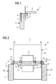
- FIG. 1 shows a schematic representation of a detail of a conventional arrangement 1 for supporting an inner casing of a steam turbine, not shown.
- the arrangement 1 comprises a plurality of support posts 2, of which in FIG. 1 only one is shown.
- Each supporting column 2 comprises a column 3 and a block 4 connected on the head side to the column 3.
- the block 4 is connected to the column 3 by means of a tie rod 5 arranged eccentrically to the column 3.
- a bearing body 6 is arranged on the block 4, which protrudes via a passage opening 10 on an axial end wall of an outer housing 7 of the steam turbine and on which a support arm 8 arranged on the inner housing rests.
- FIG. 2 shows a schematic side view of a detail of an embodiment of an inventive arrangement 11 for supporting an inner housing 12 of a steam turbine 13 in the form of a low-pressure steam turbine, which has an inner housing 12 surrounding the outer housing 14.
- the arrangement 11 comprises two in the axial direction A of the low-pressure steam turbine 13, parallel to each other and spaced from each other arranged longitudinal member 15 to which the inner housing is placed and of which FIG. 2 only one longitudinal member 15 is shown.
- the longitudinal members 15 are formed by a predetermined amount longer than an axial length L of the outer housing 14 and each have two end-side support portions 16 and 17, which are smaller than the respective remaining side member 15 dimensioned.
- At axial end regions 18 in the form of end walls of the outer housing 14 are each at least two transverse to the image plane successive through holes 19 are formed through which a single support portion 16 and 17 is guided sealed.
- the arrangement 11 comprises four arranged outside the outer housing 14 supports 20, on each of which a support portion 16 and 17 is placed by a longitudinal member 15, wherein on axially opposite sides of the outer housing 14 each two supports 20 are arranged.
- FIG. 2 only one support 20 is shown.
- Each support 20 has a support column 21 and a head block on the support column 21 arranged support block 22.
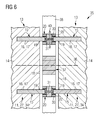
- the supports 20 are arranged separately from a support bearing a shaft bearing housing of the low-pressure steam turbine 13, as it FIG. 6 shows.
- the support portions 16 and 17 of the longitudinal member 15 are arranged by a predetermined amount in the transverse direction of the low-pressure steam turbine 13 and in the horizontal direction floating on the respective support 20, as for example in the Figures 3 and 6 is indicated. Furthermore, the support portion 17 of the longitudinal member 15 by a predetermined amount arranged in the axial direction A of the steam turbine 13 floating on the support 20 shown on the right, which should be indicated by the double arrow 23. By contrast, the supporting section 16 resting on the support 20 shown on the left is connected immovably to this support 20 in the axial direction A of the steam turbine 13.
- the arrangement 11 also comprises four support bodies 24 which can be arranged spaced apart from one another on the inner housing 12, wherein two bearing sections 25 arranged one behind the other in the axial direction A of the steam turbine 13 are arranged on an upper side of each longitudinal support 15.
- the support bodies 24 are arranged on the inner housing 12 such that a single support body 24 is placed on each bearing section 25.
- the bearing section 25 shown on the left side of the longitudinal member 15 is immovably connected to the resting on this bearing portion 25 support body 24, whereas on the bearing portion 25 shown on the right side of this longitudinal support 15 resting support body 24 is placed in the horizontal direction floating on this bearing portion 25, to which the bearing portion 25th slightly larger than the support body 24 is formed.
- the arrangement 11 further comprises four each arranged on a through hole 19 of the outer housing 14 compensators 26, each of which is arranged to compensate for relative movements of a respective guided through this passage opening 19 support portion 16 and 17 of a longitudinal member 15 and over which the support portions 16 and 17 opposite the outer housing 14 are sealed.
- FIG. 3 shows a schematic end view of a detail of another embodiment of an inventive arrangement 27.
- a slider 28 is disposed on the laid on this support 20 support portion 16 and 17 of a longitudinal member 15 is up.
- the support block 22 of the support 20 is centered connected via a in the axial direction of the support column 21 of this support 20 extending tie rods 29 with the support column 21 of this support 20.
- a metallic base plate 30 is arranged between the support block 22 and the support column 21, a metallic base plate 30 is arranged.
- an axially extending coupling member 31 is arranged, via which this longitudinal member 15 is mechanically coupled to a corresponding side member 15 of a arranged adjacent to the steam turbine 13 another steam turbine arranged corresponding arrangement 11, as it in FIG. 6 is shown.
- the support section 16 or 17 is placed in the transverse direction of the steam turbine 13 and floating in the horizontal direction on the support 20, which should be indicated by the double arrow 39.
- FIG. 4 shows a schematic side view of the in FIG. 3 shown on the support block 22 of the support 20 are two extending in the transverse direction of the steam turbine 13 and in the horizontal direction through-openings 32 and 33 formed with different inner diameter, through each of which a lubricant to a shaft bearing, not shown, the steam turbine 13 conductive or of the shaft bearing dissipative, not shown line can be laid.
- FIG. 5 shows a schematic side view of a detail of another embodiment of an inventive arrangement 34.
- This arrangement 34 differs in particular from that in the FIGS. 3 and 4 shown arrangement 11 in that on the support block 22 no feedthrough openings 32 and 33 are formed and that no base plate 30 is present.
- the tie rod 29, via which the support block 22 is connected to the support column 21, is in FIG. 5 not shown.
- FIG. 12 shows a schematic plan view of a detail of an exemplary embodiment of a system 35 according to the invention.
- the system 35 comprises two via a line 36 indicated rotor shaft mechanically coupled to each other steam turbines 13 in the form of low pressure steam turbines, each steam turbine 13 having an assembly 11, 27 or 34, and wherein mutually aligned side members 15 of the assemblies 11, 27 and 34 are mechanically coupled in pairs via a coupling member 31 rigidly to each other ,
- a shaft bearing housing 37 is arranged, which is supported by a supporting post, not shown, wherein the supports 20 are arranged separately from the support post.
- the supports 20 and their support columns 21, not shown, and the supporting support of the shaft bearing housing 37 are connected to a common foundation plate 38.
- the support portions 16 and 17 of in FIG. 6 The longitudinal members 15 shown above are placed in the transverse direction of the steam turbine 13 and floating in the horizontal direction on the support 20 shown above, which should be indicated by the double arrow 40.
- the support portions 16 and 17 of in FIG. 6 Longitudinal members 15 shown below are arranged immovably on the lower support 20 in the transverse direction of the steam turbine 13 and in the horizontal direction.
Landscapes
- Engineering & Computer Science (AREA)
- Mechanical Engineering (AREA)
- General Engineering & Computer Science (AREA)
- Turbine Rotor Nozzle Sealing (AREA)
Priority Applications (2)
| Application Number | Priority Date | Filing Date | Title |
|---|---|---|---|
| EP14172283.5A EP2955338A1 (fr) | 2014-06-13 | 2014-06-13 | Système de support d'un boîtier intérieur d'une turbine à vapeur |
| PCT/EP2015/059449 WO2015188978A1 (fr) | 2014-06-13 | 2015-04-30 | Arrangement pour porter un carter interne d'une turbine à vapeur |
Applications Claiming Priority (1)
| Application Number | Priority Date | Filing Date | Title |
|---|---|---|---|
| EP14172283.5A EP2955338A1 (fr) | 2014-06-13 | 2014-06-13 | Système de support d'un boîtier intérieur d'une turbine à vapeur |
Publications (1)
| Publication Number | Publication Date |
|---|---|
| EP2955338A1 true EP2955338A1 (fr) | 2015-12-16 |
Family
ID=50972488
Family Applications (1)
| Application Number | Title | Priority Date | Filing Date |
|---|---|---|---|
| EP14172283.5A Withdrawn EP2955338A1 (fr) | 2014-06-13 | 2014-06-13 | Système de support d'un boîtier intérieur d'une turbine à vapeur |
Country Status (2)
| Country | Link |
|---|---|
| EP (1) | EP2955338A1 (fr) |
| WO (1) | WO2015188978A1 (fr) |
Citations (3)
| Publication number | Priority date | Publication date | Assignee | Title |
|---|---|---|---|---|
| FR1090287A (fr) * | 1953-01-29 | 1955-03-29 | Parsons & Marine Eng Turbine | Turbines à fluide élastique |
| US20110142605A1 (en) * | 2009-12-16 | 2011-06-16 | General Electric Company | Low-pressure steam turbine hood and inner casing supported on curb foundation |
| DE102012103890A1 (de) * | 2011-05-05 | 2012-11-08 | General Electric Company | Abstützungsanordnung für das Niederdruckgehäuse einer Dampfturbine |
-
2014
- 2014-06-13 EP EP14172283.5A patent/EP2955338A1/fr not_active Withdrawn
-
2015
- 2015-04-30 WO PCT/EP2015/059449 patent/WO2015188978A1/fr not_active Ceased
Patent Citations (3)
| Publication number | Priority date | Publication date | Assignee | Title |
|---|---|---|---|---|
| FR1090287A (fr) * | 1953-01-29 | 1955-03-29 | Parsons & Marine Eng Turbine | Turbines à fluide élastique |
| US20110142605A1 (en) * | 2009-12-16 | 2011-06-16 | General Electric Company | Low-pressure steam turbine hood and inner casing supported on curb foundation |
| DE102012103890A1 (de) * | 2011-05-05 | 2012-11-08 | General Electric Company | Abstützungsanordnung für das Niederdruckgehäuse einer Dampfturbine |
Also Published As
| Publication number | Publication date |
|---|---|
| WO2015188978A1 (fr) | 2015-12-17 |
Similar Documents
| Publication | Publication Date | Title |
|---|---|---|
| DE102009059317B4 (de) | Selbstausrichtende Lageranordnung für drehbare zylindrische Komponenten | |
| EP2407646B1 (fr) | Méthode et dispositif pour l'ajustement de la position du rotor d'une turbine à gas ou à vapeur | |
| DE2128245A1 (de) | Maschine mit einem Rotor | |
| DE102008002852B4 (de) | Stützschiene mit anpassbarer Scheibenanordnung für Turbinendeckscheiben | |
| DE3216626C2 (de) | Auf einer Grundplatte aufgestellte Gasturbinenanlage | |
| DE102020108248B3 (de) | Vorrichtung zum Montieren und Demontieren eines Lagersegments einer Lageranordnung für einen Rotor einer Windkraftanlage | |
| DE102012103890A1 (de) | Abstützungsanordnung für das Niederdruckgehäuse einer Dampfturbine | |
| DE202016101702U1 (de) | Wellenantriebseinrichtung und damit ausgestattete Vorrichtung | |
| EP3495632A1 (fr) | Structure portante intégrée pour un moteur d'avion et ses composants accessoires | |
| EP3333439B1 (fr) | Procédé de remplacement du palier usé, en particulier de remplacement du palier de grand diamètre comme palier principal d'une éolienne et dispositif de palier | |
| EP0690260B1 (fr) | Procédé de remplacement d'un élément de machine | |
| DE102011057076A1 (de) | Abnehmbare Dampfeinlassanordnung für eine Dampfturbine | |
| DE102019131245B4 (de) | Lageranordnung und Verfahren zum Montieren einer solchen | |
| EP3176386B1 (fr) | Système de virole interne, virole interne, boîtier intermédiaire et turbomachine associés | |
| EP2955338A1 (fr) | Système de support d'un boîtier intérieur d'une turbine à vapeur | |
| DE19925779A1 (de) | Abgasturbolader mit einem Notöltank | |
| EP3837430B1 (fr) | Procédé d'assemblage d'un agencement de turbine à gaz sur une fondation | |
| EP3134676B1 (fr) | Échangeur de chaleur | |
| CH714851A2 (de) | Turbolader. | |
| CH714944A2 (de) | Turbolader. | |
| EP2230388B1 (fr) | Turbine et support | |
| WO2012025262A1 (fr) | Convertisseur basculant à suspension à baguettes pendulaires | |
| EP0754856A2 (fr) | Turbine bulbe | |
| DE112017001433T5 (de) | System und verfahren zum stützen einer kesselbeladung | |
| EP3922449B1 (fr) | Unité hydraulique pour une presse à filer, série de telles unités et presse à filer pourvue de l'unité hydraulique |
Legal Events
| Date | Code | Title | Description |
|---|---|---|---|
| PUAI | Public reference made under article 153(3) epc to a published international application that has entered the european phase |
Free format text: ORIGINAL CODE: 0009012 |
|
| AK | Designated contracting states |
Kind code of ref document: A1 Designated state(s): AL AT BE BG CH CY CZ DE DK EE ES FI FR GB GR HR HU IE IS IT LI LT LU LV MC MK MT NL NO PL PT RO RS SE SI SK SM TR |
|
| AX | Request for extension of the european patent |
Extension state: BA ME |
|
| STAA | Information on the status of an ep patent application or granted ep patent |
Free format text: STATUS: THE APPLICATION IS DEEMED TO BE WITHDRAWN |
|
| 18D | Application deemed to be withdrawn |
Effective date: 20160617 |