EP2955561B1 - Optische deflektorvorrichtung mit fähigkeit zur erhöhung der ausgleichsdeflektionsmenge eines spiegels - Google Patents
Optische deflektorvorrichtung mit fähigkeit zur erhöhung der ausgleichsdeflektionsmenge eines spiegels Download PDFInfo
- Publication number
- EP2955561B1 EP2955561B1 EP15171555.4A EP15171555A EP2955561B1 EP 2955561 B1 EP2955561 B1 EP 2955561B1 EP 15171555 A EP15171555 A EP 15171555A EP 2955561 B1 EP2955561 B1 EP 2955561B1
- Authority
- EP
- European Patent Office
- Prior art keywords
- piezoelectric
- mirror
- drive voltage
- cantilevers
- optical deflector
- Prior art date
- Legal status (The legal status is an assumption and is not a legal conclusion. Google has not performed a legal analysis and makes no representation as to the accuracy of the status listed.)
- Active
Links
Images






Classifications
-
- G—PHYSICS
- G02—OPTICS
- G02B—OPTICAL ELEMENTS, SYSTEMS OR APPARATUS
- G02B26/00—Optical devices or arrangements for the control of light using movable or deformable optical elements
- G02B26/08—Optical devices or arrangements for the control of light using movable or deformable optical elements for controlling the direction of light
- G02B26/0816—Optical devices or arrangements for the control of light using movable or deformable optical elements for controlling the direction of light by means of one or more reflecting elements
- G02B26/0833—Optical devices or arrangements for the control of light using movable or deformable optical elements for controlling the direction of light by means of one or more reflecting elements the reflecting element being a micromechanical device, e.g. a MEMS mirror, DMD
- G02B26/0858—Optical devices or arrangements for the control of light using movable or deformable optical elements for controlling the direction of light by means of one or more reflecting elements the reflecting element being a micromechanical device, e.g. a MEMS mirror, DMD the reflecting means being moved or deformed by piezoelectric means
-
- B—PERFORMING OPERATIONS; TRANSPORTING
- B81—MICROSTRUCTURAL TECHNOLOGY
- B81B—MICROSTRUCTURAL DEVICES OR SYSTEMS, e.g. MICROMECHANICAL DEVICES
- B81B3/00—Devices comprising flexible or deformable elements, e.g. comprising elastic tongues or membranes
- B81B3/0035—Constitution or structural means for controlling the movement of the flexible or deformable elements
- B81B3/004—Angular deflection
- B81B3/0043—Increasing angular deflection
-
- B—PERFORMING OPERATIONS; TRANSPORTING
- B81—MICROSTRUCTURAL TECHNOLOGY
- B81B—MICROSTRUCTURAL DEVICES OR SYSTEMS, e.g. MICROMECHANICAL DEVICES
- B81B2201/00—Specific applications of microelectromechanical systems
- B81B2201/04—Optical MEMS
- B81B2201/042—Micromirrors, not used as optical switches
Definitions
- the presently disclosed subject matter relates to an optical deflector apparatus.
- the optical deflector apparatus can be applied as an optical scanner to a laser pico projector, a laser radar, a bar code reader, an area sensor, an adaptive front-lighting system (AFS) type head lamp, a head-up display unit, and other optical apparatuses, to generate scanning light.
- AFS adaptive front-lighting system
- an optical deflector apparatus is constructed by a micro electro mechanical system (MEMS) device manufactured by using semiconductor manufacturing processes and micro machine technology.
- MEMS micro electro mechanical system
- a prior art optical deflector apparatus as a MEMS device is constructed by a mirror, an outer frame (fixed frame) surrounding the mirror, piezoelectric actuators coupled between the mirror and the outer frame, serving as cantilevers for rocking the mirror with respect to an axis (X-axis) of the mirror in a rocking operation mode (see: JP 2012-198314 A ).
- an AFS control when a steering angle read from a steering angle sensor or the like is larger than a predetermined value, the area of high luminous intensities needs to be shifted from a central position of the head lamp to a right side or a left side of the head lamp, to substantially decline the optical axis of the head lamp while the visibility in a high-beam mode is maintained. If such an AFC control is applied to the above-described prior art optical deflector apparatus, an offset voltage is applied to the piezoelectric actuators to deflect the mirror around the X-axis. This is called an offset operation mode.
- rocking drive voltages are offset by an offset voltage corresponding to the shifted amount of the optical axis of the head lamp, for example.
- the offset voltage is combined with the rocking drive voltages to generate combined drive voltages which are applied to the piezoelectric actuators (see: Figs. 14 , 15 , 16 and 17 of JP 2012-198314 A ).
- the piezoelectric actuators are used commonly for a rocking operation mode and an offset operation mode.
- US 2007/008401 A1 discloses a scanning apparatus for a printer or similar instrument.
- a multiharmonic oscillator is used to provide a composite motion of a laser beam or other light beam to scan an imaging surface.
- the multiharmonic oscillator may have multiple sections each having a different resonant frequency.
- One section includes a reflector that intercepts the light beam, and drive electronics move the reflector so the light beam scans the imaging surface. Linear and complex non-linear motions of the light beam may be achieved.
- Microelectromechanical systems (MEMS) technology may be used to fabricate the oscillator.
- WO 2010/131556 A1 discloses a piezoelectric actuator which comprises a pair of center beams, a pair of meandering beams, and a fixing frame.
- the pair of center beams extend in a first direction and are connected to an object to be driven, thereby supporting the object to be driven, from both sides thereof in the first direction.
- the pair of meandering beams include zigzag beam groups wherein the mutually adjacent end sections of a plurality of beams extending in parallel to the second direction orthogonal to the first direction are alternately connected at both ends and the beams are each provided with a piezoelectric element, so that the angles of inclination in the second direction can be accumulated by the elongation and contraction of the piezoelectric elements.
- the fixing frame surrounds the object to be driven, the center beams, and the meandering beams.
- the pair of meandering beams are arranged symmetrically so as to surround the object to be driven and the center beams from both sides thereof.
- WO 2013/114917 A1 discloses a MEMS device in which first drive units are divided into first drive portions and second drive portions. Second drive units are divided into third drive portions and fourth drive portions. The first drive portions, the second drive portions, the third drive portions, and the fourth drive portions are driven and controlled independently of each other, and an optical component is thereby tilted.
- an optical deflector apparatus is provides as set forth in claim 1. Preferred embodiments of the present invention may be gathered from the dependent claims.
- the offset deflecting amount (angle) can be increased, and also, the rocking amount (angle) can be increased.
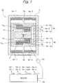
- FIG. 1 which illustrates a first embodiment of the optical deflector apparatus according to the presently disclosed subject matter as a one-dimensional MEMS device
- reference numeral 10 designates a one-dimensional optical deflector
- 20 designates a driver for driving the optical deflector
- 30 designates a laser light source.
- the optical deflector 10 is constructed by a rectangular mirror 1 for reflecting incident light L from the laser light source 30, a rectangular inner frame (movable frame) 2 surrounding the mirror 1, and a rectangular outer frame (fixed frame) surrounding the inner frame 2.
- a pair of meander-type inner piezoelectric actuators 4a and 4b are coupled between coupling portions 1a and 1b of the mirror 1 and inner coupling portions 2a and 2b of the inner frame 2 and serving as cantilevers for rocking the mirror 1 around an X-axis on the plane of the mirror 1 centered at the center 0 of the mirror 1.
- the inner piezoelectric actuators 4a and 4b are arranged opposite to each other with respect to the mirror 1.
- a pair of torsion bars 5a and 5b are coupled to outer circumferences of the inner frame 2 along the X-axis.
- linear outer piezoelectric actuators 6a-1 and 6a-2 are coupled between the torsion bar 5a and the outer frame 3
- linear outer piezoelectric actuators 6b-1 and 6b-2 are coupled between the torsion bar 5b and the outer frame 3.
- the flexing direction of the outer piezoelectric actuators 6a-1 and 6b-1 are opposite to that of the outer piezoelectric actuators 6b-1 and 6b-2, so that the outer piezoelectric actuators 6a-1, 6a-2, 6b-1 and 6b-2 serve as cantilevers for rocking the mirror 1 around the X-axis.
- the torsion bars 5a and 5b can be coupled to the outer frame 3.
- the mirror 1 can be square, rectangular, polygonal or elliptical.
- the meander-type inner piezoelectric actuators 4a and 4b are symmetrical to each other with respect to the Y-axis.
- the meander-type inner piezoelectric actuator 4a is constructed by piezoelectric cantilevers 4a-1s, 4a-2 and 4a-3s which are serially-coupled from the coupling portion 1a of the mirror 1 to a coupling portion 2a of the inner frame 2 via folded portions Fa 12 and Fa 23 . Also, each of the piezoelectric cantilevers 4a-1s, 4a-2 and 4a-3s is in parallel with the Y-axis.
- the piezoelectric cantilevers 4a-1s, 4a-2 and 4a-3s are folded at their ends or meandering from the mirror 1 to the inner frame 2, so that the amplitudes of the piezoelectric cantilevers 4a-1s, 4a-2 and 4a-3s can be changed along directions perpendicular to the X-axis.
- the meander-type inner piezoelectric actuator 4b is constructed by piezoelectric cantilevers 4b-1s, 4b-2 and 4b-3s which are serially-coupled from the coupling portion 1b of the mirror 1 to an inner coupling portion 2b of the inner frame 2 via folded portions Fb 12 and Fb 23 .
- each of the piezoelectric cantilevers 4b-1s, 4b-2 and 4b-3s are in parallel with the Y-axis.
- the piezoelectric cantilevers 4b-1s, 4b-2 and 4b-3s are folded at their ends or meandering from the mirror 1 to the inner frame 2, so that the piezoelectric cantilevers 4b-1s, 4b-2 and 4b-3s can be changed along directions perpendicular to the X-axis.
- the meander-type inner piezoelectric actuators 4a (4b) operate as follows.
- the piezoelectric cantilevers 4a-1s, 4a-2 and 4a-3s (4b-1s, 4b-2 and 4b-3s) are divided into an odd-numbered group of the piezoelectric cantilevers 4a-1s and 4a-3s (4b-1s and 4b-3s), and an even-numbered group of the piezoelectric cantilever 4a-2 (4b-2) alternating with the odd-numbered group of the piezoelectric cantilevers 4a-1s and 4a-3s (4b-1s and 4b-3s).
- the piezoelectric cantilevers 4a-1s, 4a-2 and 4a-3s are as illustrated in Fig. 2A .
- the odd-numbered group of the piezoelectric cantilevers 4a-1s and 4a-3s are flexed in the downward direction D
- the even-numbered group of the piezoelectric cantilever 4a-2 is flexed in the upward direction U.
- the flexing amounts of the piezoelectric cantilevers 4a-1s and 4a-3s are about half of that of the piezoelectric cantilever 4a-2; however, the flexing center of the piezoelectric actuator 4a is close to the center thereof.
- the mirror 1 is flexed around the X-axis by the inner piezoelectric actuators 4a and 4b.
- the number of piezoelectric cantilevers in each of the inner piezoelectric actuators 4a and 4b can be other values such as 4, 5, ⁇ .
- the torsion bars 5a and 5b have ends coupled to the outer circumference of the inner frame 2. Therefore, the torsion bars 5a and 5b are twisted by the outer piezoelectric actuators 6a-1, 6a-2, 6b-1 and 6b-2 to rock the mirror 1 around the X-axis. Other ends of the torsion bars 5a and 5b can be coupled to the inner circumference of the outer frame 3.
- a silicon-on-insulator (SOI) structure constructed by a monocrystalline silicon support layer ("Handle” layer) 301, an intermediate (buried) silicon dioxide layer ("Box” layer) 302, and a monocrystalline silicon active layer ("Device” layer) 303 is prepared. Also, by a thermal oxidation process, a silicon dioxide layer 304 is formed on the support layer 301, and a silicon dioxide layer 305 is formed on the active layer 303. Further, piezoelectric actuator cantilevers 4a-1s, 4a-2, 4a-3s, 4b-1s, 4b-2, 4b-3s and the piezoelectric actuators 6b-1 and 6b-2 are formed on the silicon dioxide layer 305.
- a Pt/Ti lower electrode layer 306 consisting of an about 50 nm thick Ti and an about 150 nm thick Pt on Ti is formed by a sputtering process.
- an about 3 ⁇ m thick PZT layer 307 is deposited on the lower electrode layer 306 by an arc discharge reactive ion plating (ADRIP) process at a temperature of about 500°C to 600°C.
- an about 150 nm thick Ti upper electrode layer 308 is formed on the PZT layer 307 by a sputtering process.
- the upper electrode layer 308 and the PZT layer 307 are patterned by a photolithography and etching process.
- the lower electrode layer 306 and the silicon dioxide layer 305 are patterned by a photolithography and etching process.
- an about 500 nm thick silicon dioxide interlayer 309 is formed on the entire surface by a plasma chemical vapor deposition (CVD) process.
- CVD plasma chemical vapor deposition
- contact holes are perforated in the silicon dioxide interlayer 309 by a photolithography and dry etching process.
- the contact holes correspond to the piezoelectric cantilevers 4a-1s, 4a-2, 4a-3s, 4b-1s, 4b-2 and 4b-3s, the piezoelectric actuators 6a-1, 6a-2, 6b-1 and 6b-2 and the pads P formed on the outer frame 3.
- wiring layers 310 made of AlCu (1%Cu) are formed by a photolithography process, a sputtering process, and a lift-off process.
- the wiring layers 310 are electrically connected between the upper electrode layers 308 of the piezoelectric cantilevers 4a-1s, 4a-2, 4a-3s, 4b-1s, 4b-2 and 4b-3s and the piezoelectric actuators 6a-1, 6a-2, 6b-1 and 6b-2 and their corresponding pads P.
- the silicon dioxide layer 304 is etched by a photolithography and dry etching process, so that the silicon dioxide layer 304 is left in an area corresponding to the inner frame 2 and the outer frame 3.
- the support layer 301 is etched by a dry etching process using the silicon dioxide layer 304 as an etching mask. Then, the silicon dioxide layer 302 is etched by a wet etching process using the support layer 301 as an etching mask.
- an aluminum (Al) reflective metal layer 311 is formed by an evaporation process on the active layer 303, and is patterned by a photolithography and etching process, thus completing the optical deflector 10.
- the torsion bars 5a and 5b are formed by the active layer 303.
- Fig. 4 is a graph for explaining the deflection angle and offset angle of the mirror 1 of Fig. 1 .
- the driver 20 controls the outer piezoelectric actuators 6a-1, 6a-2, 6b-1 and 6b-2 using sinusoidal-wave voltages V X1 and V X2 opposite in phase to each other, so that the rocking angle of the mirror 1 is from - ⁇ to + ⁇ with respect to a normal line n1 normal to the plane m1 of the mirror 1 as illustrated in Fig. 4 .
- the driver 20 controls the inner piezoelectric actuators 4a and 4b using saw-tooth drive voltages V OFFSET1 and V OFFSET2 opposite in phase to each other, so that the rocking angle of the mirror 1 is shifted by ⁇ OFFSET , so that the plane m1 of the mirror 1 is rotated by ⁇ OFFSET to a plane m2 with a normal line n2 as illustrated in Fig. 4 .
- the driver 20 also controls the outer piezoelectric actuators 6a-1, 6a-2, 6b-1 and 6b-2 using the above-mentioned sinusoidal-wave voltages V X1 and V X2 , so that the rocking angle of the mirror 1 is from - ⁇ to + ⁇ with respect to the normal line n2, i. e. , from - ⁇ - ⁇ OFFSET to + ⁇ - ⁇ OFFSET with respect to the normal line n1.
- Rocking sinusoidal-wave drive voltages V X1 and V X2 opposite in phase to each other as illustrated in Figs. 5A and 5B are applied by the driver 20 to the outer piezoelectric actuators 6a-1 and 6a-2, respectively, so that the outer piezoelectric actuators 6a-1 and 6a-2 carry out flexing operations in opposite directions to each other, which would distort the torsion bar 5a in a direction to cause a torque in the mirror 1 around the X-axis.
- the above-mentioned rocking sinusoidal-wave drive voltages V X1 and V X2 are applied by the driver 20 to the outer piezoelectric actuators 6b-1 and 6b-2, respectively, so that the outer piezoelectric actuators 6b-1 and 6b-2 carry out flexing operations in opposite directions to each other, which also would distort the torsion bar 5b in the above-mentioned direction to cause a torque in the mirror 1 around the X-axis.
- the torsion bars 5a and 5b are twisted to rock the mirror 1 around the X-axis.
- the frequency f X of the sinusoidal-wave drive voltages V X1 and V X2 is a resonant frequency such as 20kHz of a mechanical vibrating system of the mirror 1 with respect to the X-axis depending upon the mirror 1, the inner frame 2 and the inner piezoelectric actuators 4a and 4b, the rocking angle of the mirror 1 can further be enhanced.
- An offset saw-tooth drive voltage V OFFSET1 as illustrated in Fig. 5C is applied by the driver 20 to the odd-numbered piezoelectric cantilevers 4a-1s and 4a-3s of the inner piezoelectric actuator 4a and the odd-numbered piezoelectric cantilevers 4b-1s and 4b-3s of the inner piezoelectric actuator 4b.
- an offset drive voltage V OFFSET2 as illustrated in Fig. 5D opposite in phase to the offset drive voltage V OFFSET1 is applied by the driver 20 to the even-numbered piezoelectric cantilever 4a-2 of the inner piezoelectric actuator 4a and the even-numbered piezoelectric cantilever 4b-2 of the inner piezoelectric actuator 4b.
- the odd-numbered piezoelectric cantilevers 4a-1s, 4a-3s; 4b-1s, 4b-3s and the even-numbered piezoelectric cantilevers 4a-2 and 4b-2 carry out flexing operations in opposite directions to each other. As a result, the mirror 1 is flexed in one direction.
- the offset drive voltage V OFFSET1 is rectangular-wave shaped as indicated by a solid line in Fig. 5C
- the offset drive voltage V OFFSET2 is pulse-shaped as indicated by a solid line in Fig. 5D .
- the offset drive voltage V OFFSET2 can be L(low level).
- the offset drive voltage V OFFSET1 is pulse-shaped as indicated by a dotted line in Fig. 5C
- the offset drive voltage V OFFSET2 is rectangular-wave shaped as indicated by a dotted line Fig. 5D .
- the offset drive voltage V OFFSET1 can be L (low level).
- the offset drive voltages V OFFSET1 and V OFFSET2 have the same frequency f X of the rocking sinusoidal-wave drive voltages V x1 and V x2 .
- the amplitude of the rectangular-waved offset drive voltage V OFFSET1 or V OFFSET2 corresponds to an offset angle of the mirror 1.
- T A is an image active period
- T B is a blanking period. That is, in a horizontal scanning by the rocking sinusoidal-wave drive voltages V x1 and V x2 , the scanning speed is constant in the image active period T A , while the scanning speed is low in the blanking period T B . Therefore, since image display is impossible in the blanking period T B , the offset drive voltages V OFFSET1 and V OFFSET2 are inactive or pulse-shaped.
- the offset drive voltages V OFFSET1 and V OFFSET2 can always be active even in the blanking period T B ; however, in this case, charges may be stored in the PZT layer 308 so that the polarization within the PZT layer 308 would be decreased to decrease the offset angle of the mirror 1.Contrary to this, as stated above, when the offset drive voltages V OFFSET1 and V OFFSET2 are caused to be inactive or pulse-shaped in the blanking period T B , the charges stored in the PZT layer 308 are emitted to recover the offset angle corresponding to the rectangular-waved offset drive voltage V OFFSET1 or V OFFSET2 in the active period T A .
- the lengths of the piezoelectric cantilevers can be the same, so that the flexing amounts of the piezoelectric cantilevers can be enhanced.
- the piezoelectric cantilevers 4a-1s, 4a-2 and 4a-3s and the piezoelectric cantilevers 4b-1s, 4b-2 and 4b-3s can be symmetrical with respect to the center 0 of the mirror 1.
- the offset drive voltage V OFFSET1 is applied to the piezoelectric cantilevers 4a-1s, 4a-3s and 4b-2
- the offset drive voltage V OFFSET2 is applied to the piezoelectric cantilevers 4b-1s, 4b-3s and 4a-2
- the meander-type piezoelectric cantilevers 4a and 4b can be provided between the inner frame 2 and the outer frame 3, while the piezoelectric actuators 6a-1 and 6a-2 along with the torsion bars 4a and 4b can be provided between the mirror 1 and the inner frame 2.
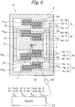
- Fig. 6 which illustrates a second embodiment of the optical deflector apparatus according to the presently disclosed subject matter
- the torsion bars 5a and 5b and the outer piezoelectric actuators 6a-1, 6a-2, 6b-1 and 6b-2 of Fig. 1 are replaced by a pair of meander-type outer piezoelectric actuators 7a and 7b which are symmetrical to each other with respect to the Y-axis.
- the meander-type outer piezoelectric actuator 7a is constructed by piezoelectric cantilevers 7a-1s, 7a-2 and 7a-3s which are serially-coupled from a coupling portion 2c of the inner frame 2 to a coupling portion 3a of the outer frame 3 via folded portions Fc 12 and Fc 23 . Also, each of the piezoelectric cantilevers 7a-1s, 7a-2 and 7a-3s is in parallel with the Y-axis.
- the piezoelectric cantilevers 7a-1s, 7a-2 and 7a-3s are folded at their ends or meandering from the inner frame 2 to the outer frame 3 so that the amplitudes of the piezoelectric cantilevers 7a-1s, 7a-2 and 7a-3s can be changed along directions perpendicular to the X-axis.
- the meander-type outer piezoelectric actuator 7b is constructed by piezoelectric cantilevers 7b-1s, 7b-2 and 7b-3s which are serially-coupled from a coupling portion 2d of the inner frame 2 to a coupling portion 3b of the outer frame 3 via folded portions Fd 12 and Fd 23 . Also, each of the piezoelectric cantilevers 7b-1s, 7b-2 and 7b-3s are in parallel with the Y-axis.
- the piezoelectric cantilevers 7b-1s, 7b-2 and 7b-3s are folded at their ends or meandering from the inner frame 2 to the outer frame 3 so that the piezoelectric cantilevers 7b-1s, 7b-2 and 7b-3s can be changed along directions perpendicular to the X-axis.
- the meander-type outer piezoelectric actuators 7a(7b) operate in the same way as the inner piezoelectric actuators 4a(4b).
- the mirror 1 is rocked around the X-axis by the outer piezoelectric actuators 7a and 7b.
- the number of piezoelectric cantilevers in each of the outer piezoelectric actuators 7a and 7b can be other values such as 4, 5, ⁇ .
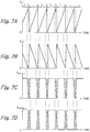
- a rocking saw-tooth drive voltage V X1 ' as illustrated in Fig. 7A is applied by the driver 20 to the odd-numbered piezoelectric cantilevers 7a-1s and 7a-3s of the outer piezoelectric actuator 7a and the odd-numbered piezoelectric cantilevers 7b-1s and 7b-3s of the inner piezoelectric actuator 7b.
- a rocking saw-tooth drive voltage V X2 ' as illustrated in Fig. 7B is applied by the driver 20 to the even-numbered piezoelectric cantilever 7a-2 of the outer piezoelectric actuator 7a and the even-numbered piezoelectric cantilever 7b-2 of the outer piezoelectric actuator 7b.
- the odd-numbered piezoelectric cantilevers 7s-1s, 7a-3s; 7b-1s, 7b-3s and the even-numbered piezoelectric cantilevers 7a-2 and 7b-2 carry out flexing operations in opposite directions to each other.
- the mirror 1 is rocked around the X-axis.
- the meander-type outer piezoelectric actuators 7a and 7b are specialized for a rocking operation mode around the X-axis
- the meander-type inner piezoelectric actuators 4a and 4b are specialized for an offset operation mode around the X-axis
- the meander-type inner piezoelectric actuators 4a and 4b can be specialized for a rocking operation mode around the X-axis
- the meander-type outer piezoelectric actuators 7a and 7b can be specialized for an offset operation mode around the X-axis.
- Fig. 8 which illustrates a first modification of the optical deflector apparatus of Fig. 6
- the meander-type inner piezoelectric actuator 4b of Fig. 6 is replaced by a meander-type inner piezoelectric actuator 4b' which is symmetrical to the meander-type inner piezoelectric actuator 4a with respect to the center 0 of the mirror 1
- the meander-type outer piezoelectric actuator 7b of Fig. 6 is replaced by a meander-type outer piezoelectric actuator 7b' which is symmetrical to the meander-type inner piezoelectric actuator 7a with respect to the center 0 of the mirror 1.
- the operation of the optical deflector of Fig. 8 is the same as that of the optical deflector of Fig.
- the rocking saw-tooth drive voltage V X1 ' is applied by the driver 20 to the piezoelectric cantilevers 7a-1s, 7a-3s and 7b-2
- the rocking saw-tooth drive voltage V X2 ' is applied by the driver 20 to the piezoelectric cantilevers 7a-2, 7b-1s and 7b-3s
- the offset saw-tooth drive voltage V OFFSET1 is applied by the driver 20 to the piezoelectric cantilevers 4a-1s, 4a-3s and 4b-2
- the offset saw-tooth drive voltage V OFFSET2 is applied by the driver 20 to the piezoelectric cantilevers 4a-2, 4b-1s and 4b-3s.
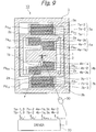
- Fig. 9 which illustrates a second modification of the optical deflector apparatus of Fig. 6
- the piezoelectric cantilevers 7a-1s, 7a-3s, 7b-1s and 7b-3s of Fig. 6 are replaced by piezoelectric cantilevers 7a-1, 7a-3, 7b-1 and 7b-3, respectively, whose length is the same as that of the piezoelectric cantilevers 7a-2 and 7b-2.
- the operation of the optical deflector of Fig. 9 is the same as that of the optical deflector of Fig. 6 , except that the rocking saw-tooth drive voltage V X1 ' is applied by the driver 20 to the piezoelectric cantilevers 7a-1, 7a-3, 7b-1 and 7b-3.
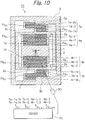
- Fig. 10 which illustrates a third modification of the optical deflector apparatus of Fig. 6
- the piezoelectric cantilevers 4a-1s, 4a-3s, 4b-1s and 4b-3s of Fig. 6 are replaced by piezoelectric cantilevers 4a-1, 4a-3, 4b-1 and 4b-3, respectively, whose length is the same as that of the piezoelectric cantilevers 4a-2 and 4b-2.
- the operation of the optical deflector of Fig. 10 is the same as that of the optical deflector of Fig. 6 , except that the offset saw-tooth drive voltage V OFFSET1 is applied by the driver 20 to the piezoelectric cantilevers 4a-1, 4a-3, 4b-1 and 4b-3.
- Fig. 11 which illustrates a fourth modification of the optical deflector apparatus of Fig. 6
- the piezoelectric cantilevers 4a-1s, 4a-3s, 4b-1s, 4b-3s, 7a-1s, 7a-3s, 7b-1s and 7b-3s of Fig. 6 are replaced by piezoelectric cantilevers 4a-1, 4a-3, 4b-1, 4b-3, 7a-1, 7a-3, 7b-1 and 7b-3, respectively, whose length is the same as that of the piezoelectric cantilevers 4a-2 and 4b-2 and the piezoelectric cantilevers 7a-2 and 7b-2.
- the rocking saw-tooth drive voltage V X1 ' is applied by the driver 20 to the piezoelectric cantilevers 7a-1, 7a-3, 7b-1 and 7b-3.
- the offset saw-tooth drive voltage V OFFSET1 is applied by the driver 20 to the piezoelectric cantilevers 4a-1, 4a-3, 4b-1 and 4b-3.
- Fig. 12 which illustrates a fifth modification of the optical deflector apparatus of Fig. 6
- the piezoelectric cantilevers 4a-1s, 4a-3s, 4b-1s and 4b-3s, 7a-1s, 7a-3s, 7b-1s and 7b-3s of Fig. 6 are replaced by piezoelectric cantilevers 4a-1, 4a-3, 4b-1, 4b-3, 7a-1, 7a-3, 7b-1 and 7b-3, respectively, whose length is the same as that of the piezoelectric cantilevers 4a-2 and 4b-2 and the piezoelectric cantilevers 7a-2, and 7b-2.
- the operation of the optical deflector of Fig. 12 is the same as that of the optical deflector of Fig. 6 , except for the following.
- the rocking saw-tooth drive voltage V X1 ' is applied by the driver 20 to the piezoelectric cantilevers 7a-1, 7a-3, 7b-1 and 7b-3.
- the offset saw-tooth drive voltage V OFFSET1 is applied by the driver 20 to the piezoelectric cantilevers 4a-1, 4a-3 and 4b-2
- the offset saw-tooth drive voltage V OFFSET2 is applied by the driver 20 to the piezoelectric cantilevers 4a-2, 4b-1 and 4b-3.
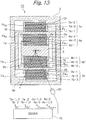
- Fig. 13 which illustrates a sixth modification of the deflector apparatus of Fig. 6
- the meander-type outer piezoelectric actuator 7b of Fig. 12 is replaced by a meander-type outer piezoelectric actuator 7b' which is symmetrical to the meander type outer piezoelectric actuator 7a of Fig. 12 with respect to the center 0 of the mirror 1.
- the operation of the optical deflector of Fig. 13 is the same as that of the optical deflector of Fig.
- rocking saw-tooth drive voltage V x1 ' is applied by the driver 20 to the piezoelectric cantilevers 7a-1, 7a-3, 7b-1 and 7b-3
- rocking saw-tooth drive voltage V x2 ' is applied by the driver 20 to the piezoelectric cantilevers 7a-2, 7b-1 and 7b-2.
- the meander-type outer piezoelectric actuators 7a and 7b (7b') are specialized for a rocking operation mode around the X-axis
- the meander-type inner piezoelectric actuators 4a and 4b (4b') are specialized for an offset operation mode around the X-axis
- the meander-type inner piezoelectric actuators 4a and 4b (4b') can be specialized for a rocking operation mode around the X-axis
- the meander-type outer piezoelectric actuators 7a and 7b (7b') can be specialized for an offset operation mode around the X-axis.
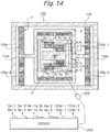
- FIG. 14 which illustrates a third embodiment of the optical deflector apparatus according to the presently disclosed subject matter as a two-dimensional MEMS device
- reference numeral 100 designates a two-dimensional optical deflector
- 200 designates a driver
- 300 designates a laser light source.
- the optical deflector 100 includes the optical deflector 10 of Fig. 1 . Additionally, in order to carry out another rocking operation mode around the Y-axis, the optical deflector 100 includes another outer frame (fixed frame) 101, a pair of torsion bars 102a and 102b coupled to the outer circumference of the outer frame 3 along the Y-axis, and linear outer piezoelectric actuators 103a-1 and 103a-2 coupled between the torsion bar 102a and the outer frame 101, and linear outer piezoelectric actuators 103b-1 and 103b-2 coupled between the torsion bar 102b and the outer frame 101.
- the outer frame 3 serves as a movable frame.
- the flexing direction of the outer piezoelectric actuators 103a-1 and 103b-1 is opposite to that of the outer piezoelectric actuators 103a-2 and 103b-2, so that each of the outer piezoelectric actuators 103a-1, 103a-2, 103b-1 and 103b-2 serves as cantilevers for rocking the mirror 1 around the Y-axis.
- the torsion bars 102a and 102b can be coupled to the outer frame 101.
- the outer frame 101 has the same structure as the outer frame 3 as illustrated in Fig. 3 .
- the pads P are formed on the outer frame 101, not on the outer frame 3.
- the torsion bars 102a and 102b have the same structure as the torsion bars 5a and 5b as illustrated in Fig. 3 .
- the linear piezoelectric actuators 103a-1, 103a-2, 103b-1 and 103b-2 have the same structure as the linear piezoelectric actuators 6a-1, 6a-2, 6b-a and 6b-2 as illustrated in Fig. 3 .
- Rocking sinusoidal-wave drive voltages V Y1 and V Y2 opposite in phase to each other as illustrated in Figs. 15A and 15B are applied by the driver 200 to the outer piezoelectric actuators 103a-1 and 103a-2, respectively, so that the outer piezoelectric actuators 103a-1 and 103a-2 carry out flexing operations in opposite directions to each other, which would distort the torsion bar 102a in a direction to cause a torque in the mirror 1 around the Y-axis.
- the above-mentioned rocking sinusoidal-wave drive voltages V Y1 and V Y2 are applied by the driver 200 to the outer piezoelectric actuators 103b-1 and 103b-2, respectively, so that the outer piezoelectric actuators 103b-1 and 103b-2 carry out flexing operations in opposite directions to each other, which would distort the torsion bar 102b in the above-mentioned direction to cause a torque in the mirror 1 around the Y-axis.
- the torsion bars 102a and 102b are twisted to rock the mirror 1 around the Y-axis.
- the frequency f Y of the rocking sinusoidal-wave drive voltages V Y1 and V Y2 is 60 Hz, for example, much lower than the resonant frequency f X of the sinusoidal-wave drive voltages V Y1 and V X2 .
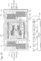
- Fig. 16 which illustrates a fourth embodiment of the optical deflector apparatus according to the presently disclosed subject matter as a two-dimensional MEMS device
- the torsion bars 102a and 102b and the linear piezoelectric actuators 103a-1, 103a-2, 103b-1 and 103b-2 of Fig. 14 are replaced by a pair of meander-type piezoelectric actuators 104a and 104b which are symmetrical to each other with respect to the X-axis.
- the piezoelectric actuator 104a is constructed by piezoelectric actuators 104a-1s, 104a-2 and 104a-3s which are serially coupled from an outer coupling portion 3c of the outer frame 3 to a coupling portion 101a of the outer frame 101 via folded portions Fe 12 and Fe 23 . Also, each of the piezoelectric cantilevers 104a-1s, 104a-2 and 104a-3s are in parallel with the X-axis.
- the piezoelectric actuators 104a-1s, 104a-2 and 104a-3s are folded at their ends or meandering from the outer frame 3 to the outer frame 101, so that amplitudes of the piezoelectric actuators 104a-1s, 104a-2 and 104a-3s can be changed along directions perpendicular to the Y-axis.
- the piezoelectric actuator 104b is constructed by piezoelectric actuators 104b-1s, 104b-2 and 104b-3s which are serially coupled from an outer coupling portion 3d of the outer frame 3 to a coupling portion 101a of the outer frame 101 via folded portions Ff 12 and Ff 23 . Also, each of the piezoelectric cantilevers 104b-1s, 104b-2 and 104b-3s are in parallel with the X-axis.
- the piezoelectric actuators 104b-1s, 104b-2 and 104b-3s are folded at their ends or meandering from the outer frame 3 to the outer frame 101, so that amplitudes of the piezoelectric actuators 104b-1s, 104b-2 and 104b-3s can be changed along directions perpendicular to the Y-axis.
- the meander-type piezoelectric actuators 104a and 104b operate in the same way as the meander-type piezoelectric actuators 4a and 4b.
- the mirror 1 is rocked around the Y-axis by the piezoelectric actuators 104a and 104b.
- the number of piezoelectric cantilevers 104a and 104b can be other values such as 4, 5, ⁇ .
- the meander-type piezoelectric actuators 104a and 104b have the same structure as the meander-type piezoelectric actuators 4a and 4b as illustrated in Fig. 3 .
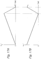
- a rocking saw-tooth drive voltage V Y1 ' as illustrated in Fig. 17A is applied by the driver 200 to the odd-numbered piezoelectric cantilevers 104a-1s and 104a-3s of the outer piezoelectric actuator 104a and the odd-numbered piezoelectric cantilevers 104b-1s and 104b-3s of the outer piezoelectric actuator 104b.
- a rocking saw-tooth drive voltage V Y2 ' as illustrated in Fig. 17B is applied by the driver 200 to the even-numbered piezoelectric cantilever 104a-2 of the outer piezoelectric actuator 104a and the even-numbered piezoelectric cantilever 104b-2 of the outer piezoelectric actuator 104b.
- the odd-numbered piezoelectric cantilevers 104a-1s, 104a-3s, 104b-1s, 104b-3s and the even-numbered piezoelectric cantilevers 104a-2 and 104b-2 carry out flexing operations in phase with each other.
- the mirror 1 is rocked around the Y-axis.
- the frequency f Y of the rocking saw-tooth drive voltages V Y1 ' and V Y2 ' is 60 Hz, for example, much lower than the resonant frequency f X of the sinusoidal-wave drive voltages V X1 and V X2.
- the length of piezoelectric cantilevers 104a-1s, 104a-3s, 104b-1s and 104b-3s is half of the piezoelectric cantilever 104a-2 and 104b-2; however, the length of piezoelectric cantilevers 104a-1s, 104a-3s, 104b-1s and 104b-3s can be the same as that of the piezoelectric cantilever 104a-2 and 104b-2. Also, the piezoelectric actuators 104a and 104b can be symmetrical to each other with respect to the center 0 of the mirror 1.
Landscapes
- Physics & Mathematics (AREA)
- General Physics & Mathematics (AREA)
- Optics & Photonics (AREA)
- Engineering & Computer Science (AREA)
- Computer Hardware Design (AREA)
- Microelectronics & Electronic Packaging (AREA)
- Mechanical Optical Scanning Systems (AREA)
- Micromachines (AREA)
- Facsimile Scanning Arrangements (AREA)
- Mechanical Light Control Or Optical Switches (AREA)
Claims (10)
- Optische Ablenkvorrichtung, die Folgendes aufweist:einen Spiegel (1);einen inneren Rahmen (2), der den Spiegel (1) umgibt;einen ersten äußeren Rahmen (3), der den inneren Rahmen (2) umgibt;eine innere piezoelektrische Betätigungsvorrichtung (4a; 4b, 4b'), die zwischen den Spiegel (1) und den inneren Rahmen (2) gekoppelt und ausgelegt ist, um den Spiegel (1) um eine erste Achse des Spiegels (1) zu beugen;eine erste äußere, piezoelektrische Betätigungsvorrichtung (6a-1, 6a-2, 6b-1, 6b-2, 7a, 7b, 7b'), die zwischen den inneren Rahmen (2) und den ersten äußeren Rahmen (3) gekoppelt und ausgelegt ist, um den Spiegel (1) um die erste Achse des Spiegels (1) zu beugen;eine Antriebsvorrichtung (20), die ausgelegt ist, um eine Versatzantriebsspannung (VOFFSET1, VOFFSET2) und eine erste Schwenkantriebsspannung (VX1, VX2; VX1', VX2') zu erzeugen,wobei die Versatzantriebsspannung (VOFFSET1, VOFFSET2) an eine erste piezoelektrische Betätigungsvorrichtung angelegt wird, die aus der inneren, piezoelektrischen Betätigungsvorrichtung (4a; 4b, 4b') und der äußeren, piezoelektrischen Betätigungsvorrichtung (6a-1, 6a-2, 6b-1, 6b-2, 7a, 7b, 7b') ausgewählt wird,wobei die erste Schwenkantriebsspannung (VX1, VX2; VX1', VX2') an eine zweite piezoelektrische Betätigungsvorrichtung angelegt wird, die sich von der ersten piezoelektrischen Betätigungsvorrichtung unterscheidet, die aus der inneren, piezoelektrischen Betätigungsvorrichtung (4a; 4b, 4b') und der äußeren, piezoelektrischen Betätigungsvorrichtung (6a-1, 6a-2, 6b-1, 6b-2, 7a, 7b, 7b') ausgewählt wird,wobei die erste piezoelektrische Betätigungsvorrichtung eine erste Gruppe von piezoelektrischen Trägern (4a-1, 4a-1s, 4a-3s, 4b-1, 4b-1s, 4b-3, 4b-3s) und eine zweite Gruppe von piezoelektrischen Trägern (4a-2, 4b-2), die sich mit der ersten Gruppe von piezoelektrischen Trägern (4a-1, 4a-1s, 4a-3s, 4b-1, 4b-1s, 4b-3, 4b-3s) abwechselt, aufweist, die an ihren Enden und parallel zu einer zweiten Achse des Spiegels (1) gefaltet sind,wobei die Versatzantriebsspannung (VOFFSET1) an die erste Gruppe von piezoelektrischen Trägern (4a-1, 4a-1s, 4a-3s, 4b-1, 4b-1s, 4b-3, 4b-3s) angelegt wird und eine invertierte Spannung (VOFFSET2) der Versatzantriebsspannung (VOFFSET1) an die zweite Gruppe von piezoelektrischen Trägern (4a-2, 4b-2) angelegt wird, undwobei die Versatzantriebsspannung (VOFFSET1) eine Rechteckwellenform in einer aktiven Periode (TA) und pulsförmig in einer Austastperiode (TB) ist.
- Optische Ablenkvorrichtung gemäß Anspruch 1, wobei die zweite piezoelektrische Betätigungsvorrichtung Folgendes aufweist:eine erste Torsionsstange (5a, 5b), die mit dem inneren Rahmen (2) gekoppelt ist;ein Paar von ersten linearen, piezoelektrischen Betätigungsvorrichtungen (6a-1, 6a-2, 6b-1, 6b-2), die zwischen den inneren Rahmen (2) und den ersten äußeren Rahmen (3) gekoppelt sind,wobei die erste Schwenkantriebsspannung (VX1) an eine der ersten linearen, piezoelektrischen Antriebsvorrichtungen (6a-1, 6b-1) angelegt wird, und eine invertierte Spannung (VX2) der ersten Schwenkantriebsspannung (VX1) an die andere der ersten linearen, piezoelektrischen Antriebsvorrichtungen (6a-1, 6b-1) angelegt wird.
- Optische Ablenkvorrichtung gemäß Anspruch 2, wobei die erste Schwenkantriebsspannung (VX1) sinuswellenförmig ist.
- Optische Ablenkvorrichtung gemäß Anspruch 1, wobei die zweite piezoelektrische Betätigungsvorrichtung eine dritte Gruppe von piezoelektrischen Trägern (7a-1, 7a-1s, 7a-3s, 7b-1, 7b-1s, 7b-3, 7b-3s) und eine vierte Gruppe von piezoelektrischen Trägern (7a-2, 7b-2) aufweist, die sich mit der dritten Gruppe von piezoelektrischen Trägern (7a-1, 7a-1s, 7a-3s, 7b-1, 7b-1s, 7b-3, 7b-3s) abwechseln, die an ihren Enden und parallel zu einer zweiten Achse des Spiegels (1) gefaltet sind,
wobei die erste Schwenkantriebsspannung (VX1') an die dritte Gruppe von piezoelektrischen Trägern (7a-1, 7a-1s, 7a-3s, 7b-1, 7b-1s, 7b-3, 7b-3s) und eine invertierte Spannung (VX2') der ersten Schwenkantriebsspannung (VX1') an die vierte Gruppe von piezoelektrischen Trägern (7a-2, 7b-2) angelegt wird. - Optische Ablenkvorrichtung gemäß Anspruch 4, wobei die erste Schwenkantriebsspannung (VX1) eine Sägezahnwellenform aufweist.
- Optische Ablenkvorrichtung gemäß Anspruch 1, die ferner Folgendes aufweist:einen zweiten äußeren Rahmen (101), der den ersten äußeren Rahmen (3) umgibt;eine zweite äußere, piezoelektrische Betätigungsvorrichtung (103a-1, 103a-2, 103b-1, 103b-2; 104a, 104b), die ausgelegt ist, um den Spiegel (1) um eine zweite Achse des Spiegels (1) zu schwenken,wobei die Antriebsvorrichtung (200) ausgelegt ist, um ferner eine zweite Schwenkantriebsspannung (VY1, VY2; VY1', VY2') zu erzeugen,wobei die zweite Schwenkantriebsspannung (VY1, VY2; VY1', VY2') an die zweite äußere, piezoelektrische Betätigungsvorrichtung (103a-1, 103a-2, 103b-1, 103b-2) angelegt wird.
- Optische Ablenkvorrichtung gemäß Anspruch 6, wobei die zweite äußere, piezoelektrische Betätigungsvorrichtung Folgendes aufweist:eine zweite Torsionsstange (5a, 5b), die mit dem inneren Rahmen (2) gekoppelt ist;ein Paar von zweiten linearen, piezoelektrischen Betätigungsvorrichtungen (103a-1, 103a-2, 103b-1, 103b-2), die zwischen die zweite Torsionsstange (5a, 5b) und den zweiten äußeren Rahmen (101) gekoppelt sind,wobei die zweite Schwenkantriebsspannung (VY1) an eine der zweiten linearen, piezoelektrischen Betätigungsvorrichtungen (103a-1, 103b-1) angelegt wird und eine invertierte Spannung (VY2) der zweiten Schwenkantriebsspannung (VY1) an die andere der zweiten linearen, piezoelektrischen Betätigungsvorrichtungen (103a-1, 103b-1) angelegt wird.
- Optische Ablenkvorrichtung gemäß Anspruch 7, wobei die zweite Schwenkantriebsspannung (VY1) sinuswellenförmig ist.
- Optische Ablenkvorrichtung gemäß Anspruch 6, wobei die zweite äußere, piezoelektrische Betätigungsvorrichtung (104a, 104b) eine fünfte Gruppe von piezoelektrischen Trägern (104a-1s, 104a-3s, 104b-1s, 104b-3s) und eine sechste Gruppe von piezoelektrischen Trägern (104a-2, 104b-2) aufweist, die sich mit der fünfte Gruppe von piezoelektrischen Trägern (104a-1s, 104a-3s, 104b-1s, 104b-3s) abwechselt, die an ihren Enden und parallel zu der ersten Achse des Spiegels (1) gefaltet sind,
wobei die zweite Schwenkantriebsspannung (VY1') an die fünfte Gruppe von piezoelektrischen Trägern (104a-1s, 104a-3s, 104b-1s, 104b-3s) angelegt wird und eine invertierte Spannung (VY2') der fünften Schwenkantriebsspannung (VY1') an die sechste Gruppe von piezoelektrischen Trägern (104a-2, 104b-2) angelegt wird. - Optische Ablenkvorrichtung gemäß Anspruch 9, wobei die zweite Schwenkantriebsspannung (VY1') eine Sägezahnwellenform aufweist.
Applications Claiming Priority (1)
| Application Number | Priority Date | Filing Date | Title |
|---|---|---|---|
| JP2014121658A JP6333079B2 (ja) | 2014-06-12 | 2014-06-12 | 光スキャナ |
Publications (2)
| Publication Number | Publication Date |
|---|---|
| EP2955561A1 EP2955561A1 (de) | 2015-12-16 |
| EP2955561B1 true EP2955561B1 (de) | 2018-01-10 |
Family
ID=53397876
Family Applications (1)
| Application Number | Title | Priority Date | Filing Date |
|---|---|---|---|
| EP15171555.4A Active EP2955561B1 (de) | 2014-06-12 | 2015-06-11 | Optische deflektorvorrichtung mit fähigkeit zur erhöhung der ausgleichsdeflektionsmenge eines spiegels |
Country Status (3)
| Country | Link |
|---|---|
| US (1) | US9488828B2 (de) |
| EP (1) | EP2955561B1 (de) |
| JP (1) | JP6333079B2 (de) |
Families Citing this family (18)
| Publication number | Priority date | Publication date | Assignee | Title |
|---|---|---|---|---|
| JP6975410B2 (ja) * | 2015-06-03 | 2021-12-01 | 株式会社リコー | 回動装置、光走査装置、画像表示装置、移動体、回動動作調整方法及びプログラム |
| JP6581002B2 (ja) * | 2016-01-25 | 2019-09-25 | スタンレー電気株式会社 | 前照灯装置 |
| WO2018088291A1 (ja) * | 2016-11-09 | 2018-05-17 | 第一精工株式会社 | 可動反射素子 |
| JP6808506B2 (ja) * | 2017-01-25 | 2021-01-06 | スタンレー電気株式会社 | 光走査装置 |
| DE102017217653A1 (de) * | 2017-10-05 | 2019-04-11 | Robert Bosch Gmbh | Mikromechanisches Bauteil, Herstellungsverfahren für ein mikromechanisches Bauteil und Verfahren zum Anregen einer Bewegung eines verstellbaren Teils um eine Rotationsachse |
| JP7195078B2 (ja) * | 2018-07-20 | 2022-12-23 | スタンレー電気株式会社 | 光照射装置 |
| CN110031966B (zh) * | 2019-05-16 | 2021-12-07 | 苏州知芯传感技术有限公司 | 一种微镜及其制造方法 |
| WO2021075403A1 (en) * | 2019-10-18 | 2021-04-22 | Ricoh Company, Ltd. | Movable apparatus |
| FI20196026A1 (en) | 2019-11-28 | 2021-05-29 | Teknologian Tutkimuskeskus Vtt Oy | Improvements for driving a microelectromechanical system mirror |
| JP7459580B2 (ja) * | 2020-03-16 | 2024-04-02 | 株式会社リコー | 可動装置、画像投影装置、ヘッドアップディスプレイ、レーザヘッドランプ、ヘッドマウントディスプレイ、物体認識装置、及び移動体 |
| TWI787772B (zh) * | 2021-03-30 | 2022-12-21 | 台灣晶技股份有限公司 | 吸震式晶體振子封裝結構 |
| JP7659460B2 (ja) * | 2021-07-09 | 2025-04-09 | スタンレー電気株式会社 | 光偏向器 |
| DE102022200149A1 (de) | 2022-01-10 | 2023-07-13 | Robert Bosch Gesellschaft mit beschränkter Haftung | Mikromechanisches Bauteil |
| DE102022203334A1 (de) | 2022-04-04 | 2023-10-05 | Fraunhofer-Gesellschaft zur Förderung der angewandten Forschung eingetragener Verein | Mikromechanisches Bauteil mit einem beweglichen Auslenkelement |
| DE102023116051A1 (de) * | 2023-06-20 | 2024-12-24 | OQmented GmbH | Mems-vorrichtung mit einer hebelstruktur |
| WO2024261200A1 (de) | 2023-06-20 | 2024-12-26 | OQmented GmbH | Mems-vorrichtung mit einer haltestruktur umfassend eine federstruktur, innere rahmenstruktur und/oder hebelstruktur |
| DE102024109590B3 (de) * | 2024-04-05 | 2025-06-18 | Tdk Electronics Ag | Mikrospiegel und Projektionsvorrichtung |
| DE102024004501B4 (de) * | 2024-04-05 | 2025-12-24 | Tdk Electronics Ag | Mikrospiegel und Projektionsvorrichtung |
Family Cites Families (8)
| Publication number | Priority date | Publication date | Assignee | Title |
|---|---|---|---|---|
| US7573625B2 (en) * | 2005-07-07 | 2009-08-11 | Lexmark International, Inc. | Multiharmonic galvanometric scanning device |
| JP5320673B2 (ja) * | 2007-01-16 | 2013-10-23 | セイコーエプソン株式会社 | アクチュエータ、光スキャナおよび画像形成装置 |
| JP5172364B2 (ja) * | 2008-01-16 | 2013-03-27 | スタンレー電気株式会社 | 光偏向器 |
| JP2010263736A (ja) * | 2009-05-11 | 2010-11-18 | Mitsumi Electric Co Ltd | 圧電アクチュエータ |
| JP2012198314A (ja) | 2011-03-18 | 2012-10-18 | Ricoh Co Ltd | アクチュエータ装置、光偏向装置、光走査装置、画像形成装置及び画像投影装置 |
| JP5990917B2 (ja) | 2012-02-03 | 2016-09-14 | 船井電機株式会社 | Memsデバイスおよびプロジェクタ機能を有する電子機器 |
| CN103620477B (zh) * | 2012-02-22 | 2015-04-29 | 京瓷办公信息系统株式会社 | 光扫描装置和图像形成装置 |
| JP5398855B2 (ja) * | 2012-02-22 | 2014-01-29 | 京セラドキュメントソリューションズ株式会社 | 光走査装置及び画像形成装置 |
-
2014
- 2014-06-12 JP JP2014121658A patent/JP6333079B2/ja active Active
-
2015
- 2015-06-08 US US14/733,371 patent/US9488828B2/en active Active
- 2015-06-11 EP EP15171555.4A patent/EP2955561B1/de active Active
Non-Patent Citations (1)
| Title |
|---|
| None * |
Also Published As
| Publication number | Publication date |
|---|---|
| JP6333079B2 (ja) | 2018-05-30 |
| US9488828B2 (en) | 2016-11-08 |
| JP2016001275A (ja) | 2016-01-07 |
| EP2955561A1 (de) | 2015-12-16 |
| US20150362724A1 (en) | 2015-12-17 |
Similar Documents
| Publication | Publication Date | Title |
|---|---|---|
| EP2955561B1 (de) | Optische deflektorvorrichtung mit fähigkeit zur erhöhung der ausgleichsdeflektionsmenge eines spiegels | |
| JP4926596B2 (ja) | 光偏向器及びその製造方法 | |
| EP2953125B1 (de) | Treiber für optischen deflektor unter verwendung einer kombinierten sägezahn-treiberspannung und verfahren zur steuerung davon | |
| US9575313B2 (en) | Optical deflector including mirror with extended reinforcement rib coupled to protruded portions of torsion bar | |
| EP2781948B1 (de) | Optischer Ablenker mit durch Übergangsbalken gekoppelten mäanderartigen Piezoaktoren | |
| JP5151065B2 (ja) | 光スキャナ及び走査型プロジェクタ | |
| EP2808719B1 (de) | Optischer Deflektor mit getrennten piezoelektrischen Abschnitten auf piezoelektrischen Aktuatoren | |
| US10330922B2 (en) | Biaxial optical deflector including multiple mirror units, laser radar system, and manufacturing method | |
| US9696541B2 (en) | Two-dimensional optical deflector including two SOI structures and its manufacturing method | |
| EP3751328B1 (de) | Zweiachsiger mems-spiegel mit getrennten antrieben | |
| JP5414187B2 (ja) | 光偏向器 | |
| JP6278130B2 (ja) | 微小光学電気機械デバイスおよびその製造方法 | |
| EP2811331B1 (de) | Mems-vorrichtung und elektronisches instrument mit projektorfunktion | |
| CN104820285A (zh) | 静电驱动的mems器件 | |
| JPWO2019176204A1 (ja) | 光走査装置およびその制御方法 | |
| US9436000B2 (en) | Optical deflector including meander-type piezoelectric actuators and ill-balanced mirror structure | |
| JP6648443B2 (ja) | 光偏向器、2次元画像表示装置、光走査装置及び画像形成装置 | |
| JP5506976B2 (ja) | 光偏向器 | |
| JP2007206480A (ja) | 光走査素子 | |
| JP2009198702A (ja) | 揺動構造体、及び揺動構造体を用いた揺動体装置 | |
| US20240288683A1 (en) | Microscanner having meander spring-based mirror suspension | |
| EP4343405B1 (de) | Antriebssystem für optischen deflektor und antriebsverfahren für optischen deflektor | |
| WO2012176492A1 (ja) | 共振駆動アクチュエーター、マイクロスキャナおよび光学機器 | |
| US8581470B2 (en) | Electrode comb, micromechanical component, and method for producing an electrode comb or a micromechanical component | |
| US20250296833A1 (en) | Microscanner having a deflecting element and having spring elements curved towards same for suspension of the deflecting element in a manner capable of oscillation |
Legal Events
| Date | Code | Title | Description |
|---|---|---|---|
| PUAI | Public reference made under article 153(3) epc to a published international application that has entered the european phase |
Free format text: ORIGINAL CODE: 0009012 |
|
| AK | Designated contracting states |
Kind code of ref document: A1 Designated state(s): AL AT BE BG CH CY CZ DE DK EE ES FI FR GB GR HR HU IE IS IT LI LT LU LV MC MK MT NL NO PL PT RO RS SE SI SK SM TR |
|
| AX | Request for extension of the european patent |
Extension state: BA ME |
|
| 17P | Request for examination filed |
Effective date: 20160322 |
|
| RBV | Designated contracting states (corrected) |
Designated state(s): AL AT BE BG CH CY CZ DE DK EE ES FI FR GB GR HR HU IE IS IT LI LT LU LV MC MK MT NL NO PL PT RO RS SE SI SK SM TR |
|
| GRAP | Despatch of communication of intention to grant a patent |
Free format text: ORIGINAL CODE: EPIDOSNIGR1 |
|
| RIC1 | Information provided on ipc code assigned before grant |
Ipc: B81B 3/00 20060101ALI20170707BHEP Ipc: G02B 26/08 20060101AFI20170707BHEP |
|
| INTG | Intention to grant announced |
Effective date: 20170803 |
|
| GRAS | Grant fee paid |
Free format text: ORIGINAL CODE: EPIDOSNIGR3 |
|
| GRAA | (expected) grant |
Free format text: ORIGINAL CODE: 0009210 |
|
| AK | Designated contracting states |
Kind code of ref document: B1 Designated state(s): AL AT BE BG CH CY CZ DE DK EE ES FI FR GB GR HR HU IE IS IT LI LT LU LV MC MK MT NL NO PL PT RO RS SE SI SK SM TR |
|
| REG | Reference to a national code |
Ref country code: CH Ref legal event code: EP Ref country code: AT Ref legal event code: REF Ref document number: 963012 Country of ref document: AT Kind code of ref document: T Effective date: 20180115 |
|
| REG | Reference to a national code |
Ref country code: IE Ref legal event code: FG4D |
|
| REG | Reference to a national code |
Ref country code: DE Ref legal event code: R096 Ref document number: 602015007398 Country of ref document: DE |
|
| REG | Reference to a national code |
Ref country code: FR Ref legal event code: PLFP Year of fee payment: 4 |
|
| REG | Reference to a national code |
Ref country code: NL Ref legal event code: MP Effective date: 20180110 |
|
| REG | Reference to a national code |
Ref country code: AT Ref legal event code: MK05 Ref document number: 963012 Country of ref document: AT Kind code of ref document: T Effective date: 20180110 |
|
| PG25 | Lapsed in a contracting state [announced via postgrant information from national office to epo] |
Ref country code: NL Free format text: LAPSE BECAUSE OF FAILURE TO SUBMIT A TRANSLATION OF THE DESCRIPTION OR TO PAY THE FEE WITHIN THE PRESCRIBED TIME-LIMIT Effective date: 20180110 |
|
| PG25 | Lapsed in a contracting state [announced via postgrant information from national office to epo] |
Ref country code: CY Free format text: LAPSE BECAUSE OF FAILURE TO SUBMIT A TRANSLATION OF THE DESCRIPTION OR TO PAY THE FEE WITHIN THE PRESCRIBED TIME-LIMIT Effective date: 20180110 Ref country code: LT Free format text: LAPSE BECAUSE OF FAILURE TO SUBMIT A TRANSLATION OF THE DESCRIPTION OR TO PAY THE FEE WITHIN THE PRESCRIBED TIME-LIMIT Effective date: 20180110 Ref country code: FI Free format text: LAPSE BECAUSE OF FAILURE TO SUBMIT A TRANSLATION OF THE DESCRIPTION OR TO PAY THE FEE WITHIN THE PRESCRIBED TIME-LIMIT Effective date: 20180110 Ref country code: HR Free format text: LAPSE BECAUSE OF FAILURE TO SUBMIT A TRANSLATION OF THE DESCRIPTION OR TO PAY THE FEE WITHIN THE PRESCRIBED TIME-LIMIT Effective date: 20180110 Ref country code: ES Free format text: LAPSE BECAUSE OF FAILURE TO SUBMIT A TRANSLATION OF THE DESCRIPTION OR TO PAY THE FEE WITHIN THE PRESCRIBED TIME-LIMIT Effective date: 20180110 Ref country code: NO Free format text: LAPSE BECAUSE OF FAILURE TO SUBMIT A TRANSLATION OF THE DESCRIPTION OR TO PAY THE FEE WITHIN THE PRESCRIBED TIME-LIMIT Effective date: 20180410 |
|
| PG25 | Lapsed in a contracting state [announced via postgrant information from national office to epo] |
Ref country code: RS Free format text: LAPSE BECAUSE OF FAILURE TO SUBMIT A TRANSLATION OF THE DESCRIPTION OR TO PAY THE FEE WITHIN THE PRESCRIBED TIME-LIMIT Effective date: 20180110 Ref country code: PL Free format text: LAPSE BECAUSE OF FAILURE TO SUBMIT A TRANSLATION OF THE DESCRIPTION OR TO PAY THE FEE WITHIN THE PRESCRIBED TIME-LIMIT Effective date: 20180110 Ref country code: AT Free format text: LAPSE BECAUSE OF FAILURE TO SUBMIT A TRANSLATION OF THE DESCRIPTION OR TO PAY THE FEE WITHIN THE PRESCRIBED TIME-LIMIT Effective date: 20180110 Ref country code: BG Free format text: LAPSE BECAUSE OF FAILURE TO SUBMIT A TRANSLATION OF THE DESCRIPTION OR TO PAY THE FEE WITHIN THE PRESCRIBED TIME-LIMIT Effective date: 20180410 Ref country code: GR Free format text: LAPSE BECAUSE OF FAILURE TO SUBMIT A TRANSLATION OF THE DESCRIPTION OR TO PAY THE FEE WITHIN THE PRESCRIBED TIME-LIMIT Effective date: 20180411 Ref country code: LV Free format text: LAPSE BECAUSE OF FAILURE TO SUBMIT A TRANSLATION OF THE DESCRIPTION OR TO PAY THE FEE WITHIN THE PRESCRIBED TIME-LIMIT Effective date: 20180110 Ref country code: IS Free format text: LAPSE BECAUSE OF FAILURE TO SUBMIT A TRANSLATION OF THE DESCRIPTION OR TO PAY THE FEE WITHIN THE PRESCRIBED TIME-LIMIT Effective date: 20180510 Ref country code: SE Free format text: LAPSE BECAUSE OF FAILURE TO SUBMIT A TRANSLATION OF THE DESCRIPTION OR TO PAY THE FEE WITHIN THE PRESCRIBED TIME-LIMIT Effective date: 20180110 |
|
| REG | Reference to a national code |
Ref country code: DE Ref legal event code: R097 Ref document number: 602015007398 Country of ref document: DE |
|
| PG25 | Lapsed in a contracting state [announced via postgrant information from national office to epo] |
Ref country code: AL Free format text: LAPSE BECAUSE OF FAILURE TO SUBMIT A TRANSLATION OF THE DESCRIPTION OR TO PAY THE FEE WITHIN THE PRESCRIBED TIME-LIMIT Effective date: 20180110 Ref country code: RO Free format text: LAPSE BECAUSE OF FAILURE TO SUBMIT A TRANSLATION OF THE DESCRIPTION OR TO PAY THE FEE WITHIN THE PRESCRIBED TIME-LIMIT Effective date: 20180110 Ref country code: EE Free format text: LAPSE BECAUSE OF FAILURE TO SUBMIT A TRANSLATION OF THE DESCRIPTION OR TO PAY THE FEE WITHIN THE PRESCRIBED TIME-LIMIT Effective date: 20180110 Ref country code: IT Free format text: LAPSE BECAUSE OF FAILURE TO SUBMIT A TRANSLATION OF THE DESCRIPTION OR TO PAY THE FEE WITHIN THE PRESCRIBED TIME-LIMIT Effective date: 20180110 |
|
| PLBE | No opposition filed within time limit |
Free format text: ORIGINAL CODE: 0009261 |
|
| STAA | Information on the status of an ep patent application or granted ep patent |
Free format text: STATUS: NO OPPOSITION FILED WITHIN TIME LIMIT |
|
| PG25 | Lapsed in a contracting state [announced via postgrant information from national office to epo] |
Ref country code: SK Free format text: LAPSE BECAUSE OF FAILURE TO SUBMIT A TRANSLATION OF THE DESCRIPTION OR TO PAY THE FEE WITHIN THE PRESCRIBED TIME-LIMIT Effective date: 20180110 Ref country code: CZ Free format text: LAPSE BECAUSE OF FAILURE TO SUBMIT A TRANSLATION OF THE DESCRIPTION OR TO PAY THE FEE WITHIN THE PRESCRIBED TIME-LIMIT Effective date: 20180110 Ref country code: SM Free format text: LAPSE BECAUSE OF FAILURE TO SUBMIT A TRANSLATION OF THE DESCRIPTION OR TO PAY THE FEE WITHIN THE PRESCRIBED TIME-LIMIT Effective date: 20180110 Ref country code: DK Free format text: LAPSE BECAUSE OF FAILURE TO SUBMIT A TRANSLATION OF THE DESCRIPTION OR TO PAY THE FEE WITHIN THE PRESCRIBED TIME-LIMIT Effective date: 20180110 |
|
| 26N | No opposition filed |
Effective date: 20181011 |
|
| REG | Reference to a national code |
Ref country code: CH Ref legal event code: PL |
|
| PG25 | Lapsed in a contracting state [announced via postgrant information from national office to epo] |
Ref country code: SI Free format text: LAPSE BECAUSE OF FAILURE TO SUBMIT A TRANSLATION OF THE DESCRIPTION OR TO PAY THE FEE WITHIN THE PRESCRIBED TIME-LIMIT Effective date: 20180110 |
|
| REG | Reference to a national code |
Ref country code: BE Ref legal event code: MM Effective date: 20180630 |
|
| REG | Reference to a national code |
Ref country code: IE Ref legal event code: MM4A |
|
| PG25 | Lapsed in a contracting state [announced via postgrant information from national office to epo] |
Ref country code: MC Free format text: LAPSE BECAUSE OF FAILURE TO SUBMIT A TRANSLATION OF THE DESCRIPTION OR TO PAY THE FEE WITHIN THE PRESCRIBED TIME-LIMIT Effective date: 20180110 Ref country code: LU Free format text: LAPSE BECAUSE OF NON-PAYMENT OF DUE FEES Effective date: 20180611 |
|
| PG25 | Lapsed in a contracting state [announced via postgrant information from national office to epo] |
Ref country code: IE Free format text: LAPSE BECAUSE OF NON-PAYMENT OF DUE FEES Effective date: 20180611 Ref country code: CH Free format text: LAPSE BECAUSE OF NON-PAYMENT OF DUE FEES Effective date: 20180630 Ref country code: LI Free format text: LAPSE BECAUSE OF NON-PAYMENT OF DUE FEES Effective date: 20180630 |
|
| PG25 | Lapsed in a contracting state [announced via postgrant information from national office to epo] |
Ref country code: BE Free format text: LAPSE BECAUSE OF NON-PAYMENT OF DUE FEES Effective date: 20180630 |
|
| PG25 | Lapsed in a contracting state [announced via postgrant information from national office to epo] |
Ref country code: MT Free format text: LAPSE BECAUSE OF NON-PAYMENT OF DUE FEES Effective date: 20180611 |
|
| PG25 | Lapsed in a contracting state [announced via postgrant information from national office to epo] |
Ref country code: TR Free format text: LAPSE BECAUSE OF FAILURE TO SUBMIT A TRANSLATION OF THE DESCRIPTION OR TO PAY THE FEE WITHIN THE PRESCRIBED TIME-LIMIT Effective date: 20180110 |
|
| PG25 | Lapsed in a contracting state [announced via postgrant information from national office to epo] |
Ref country code: PT Free format text: LAPSE BECAUSE OF FAILURE TO SUBMIT A TRANSLATION OF THE DESCRIPTION OR TO PAY THE FEE WITHIN THE PRESCRIBED TIME-LIMIT Effective date: 20180110 |
|
| PG25 | Lapsed in a contracting state [announced via postgrant information from national office to epo] |
Ref country code: HU Free format text: LAPSE BECAUSE OF FAILURE TO SUBMIT A TRANSLATION OF THE DESCRIPTION OR TO PAY THE FEE WITHIN THE PRESCRIBED TIME-LIMIT; INVALID AB INITIO Effective date: 20150611 Ref country code: MK Free format text: LAPSE BECAUSE OF NON-PAYMENT OF DUE FEES Effective date: 20180110 |
|
| PGFP | Annual fee paid to national office [announced via postgrant information from national office to epo] |
Ref country code: GB Payment date: 20240502 Year of fee payment: 10 |
|
| PGFP | Annual fee paid to national office [announced via postgrant information from national office to epo] |
Ref country code: FR Payment date: 20240509 Year of fee payment: 10 |
|
| PGFP | Annual fee paid to national office [announced via postgrant information from national office to epo] |
Ref country code: DE Payment date: 20250429 Year of fee payment: 11 |
|
| GBPC | Gb: european patent ceased through non-payment of renewal fee |
Effective date: 20250611 |
|
| PG25 | Lapsed in a contracting state [announced via postgrant information from national office to epo] |
Ref country code: GB Free format text: LAPSE BECAUSE OF NON-PAYMENT OF DUE FEES Effective date: 20250611 |
|
| PG25 | Lapsed in a contracting state [announced via postgrant information from national office to epo] |
Ref country code: FR Free format text: LAPSE BECAUSE OF NON-PAYMENT OF DUE FEES Effective date: 20250630 |