EP2955828A1 - Leistungsversorgungssystem - Google Patents
Leistungsversorgungssystem Download PDFInfo
- Publication number
- EP2955828A1 EP2955828A1 EP13890645.8A EP13890645A EP2955828A1 EP 2955828 A1 EP2955828 A1 EP 2955828A1 EP 13890645 A EP13890645 A EP 13890645A EP 2955828 A1 EP2955828 A1 EP 2955828A1
- Authority
- EP
- European Patent Office
- Prior art keywords
- power source
- power
- mode
- current
- output
- Prior art date
- Legal status (The legal status is an assumption and is not a legal conclusion. Google has not performed a legal analysis and makes no representation as to the accuracy of the status listed.)
- Withdrawn
Links
Images


Classifications
-
- H—ELECTRICITY
- H02—GENERATION; CONVERSION OR DISTRIBUTION OF ELECTRIC POWER
- H02J—ELECTRIC POWER NETWORKS; CIRCUIT ARRANGEMENTS OR SYSTEMS FOR SUPPLYING OR DISTRIBUTING ELECTRIC POWER; SYSTEMS FOR STORING ELECTRIC ENERGY
- H02J7/00—Circuit arrangements for charging or discharging batteries or for supplying loads from batteries
- H02J7/34—Parallel operation in networks using both storage and other DC sources, e.g. providing buffering
-
- H—ELECTRICITY
- H02—GENERATION; CONVERSION OR DISTRIBUTION OF ELECTRIC POWER
- H02J—ELECTRIC POWER NETWORKS; CIRCUIT ARRANGEMENTS OR SYSTEMS FOR SUPPLYING OR DISTRIBUTING ELECTRIC POWER; SYSTEMS FOR STORING ELECTRIC ENERGY
- H02J1/00—Circuit arrangements for DC mains or DC distribution networks
- H02J1/10—Parallel operation of DC sources
-
- H—ELECTRICITY
- H02—GENERATION; CONVERSION OR DISTRIBUTION OF ELECTRIC POWER
- H02J—ELECTRIC POWER NETWORKS; CIRCUIT ARRANGEMENTS OR SYSTEMS FOR SUPPLYING OR DISTRIBUTING ELECTRIC POWER; SYSTEMS FOR STORING ELECTRIC ENERGY
- H02J1/00—Circuit arrangements for DC mains or DC distribution networks
- H02J1/10—Parallel operation of DC sources
- H02J1/102—Parallel operation of DC sources being switching converters
-
- H—ELECTRICITY
- H02—GENERATION; CONVERSION OR DISTRIBUTION OF ELECTRIC POWER
- H02J—ELECTRIC POWER NETWORKS; CIRCUIT ARRANGEMENTS OR SYSTEMS FOR SUPPLYING OR DISTRIBUTING ELECTRIC POWER; SYSTEMS FOR STORING ELECTRIC ENERGY
- H02J1/00—Circuit arrangements for DC mains or DC distribution networks
- H02J1/14—Balancing load and power generation in DC networks
-
- H—ELECTRICITY
- H02—GENERATION; CONVERSION OR DISTRIBUTION OF ELECTRIC POWER
- H02J—ELECTRIC POWER NETWORKS; CIRCUIT ARRANGEMENTS OR SYSTEMS FOR SUPPLYING OR DISTRIBUTING ELECTRIC POWER; SYSTEMS FOR STORING ELECTRIC ENERGY
- H02J9/00—Circuit arrangements for emergency or stand-by power supply, e.g. for emergency lighting
- H02J9/04—Circuit arrangements for emergency or stand-by power supply, e.g. for emergency lighting in which the distribution system is disconnected from the normal source and connected to a standby source
- H02J9/06—Circuit arrangements for emergency or stand-by power supply, e.g. for emergency lighting in which the distribution system is disconnected from the normal source and connected to a standby source with automatic change-over, e.g. UPS systems
-
- H—ELECTRICITY
- H02—GENERATION; CONVERSION OR DISTRIBUTION OF ELECTRIC POWER
- H02J—ELECTRIC POWER NETWORKS; CIRCUIT ARRANGEMENTS OR SYSTEMS FOR SUPPLYING OR DISTRIBUTING ELECTRIC POWER; SYSTEMS FOR STORING ELECTRIC ENERGY
- H02J9/00—Circuit arrangements for emergency or stand-by power supply, e.g. for emergency lighting
Definitions
- the present invention relates to a power source system that is configured by combining a power source unit and a battery unit and is capable of supplying power greater than the total output of the power source unit to a load by supplying power from a battery unit temporarily, in other words, a power source system having a power assist function.
- Fig. 1 is a diagram showing the configuration of a power source system disclosed in Patent Document 1.
- the power source system shown in Fig. 1 is constituted by a three-phase commercial power source E, a DC power source apparatus 501 and a load RL, and of these, the DC power source apparatus 501 is constituted by a power storage apparatus 60, a plurality of DC power source apparatus units 1 to N, one charging/spare unit, and a monitoring unit 81 including an operational state determination unit 82, an output voltage monitoring unit 83, a droop operation control unit 84, a charging voltage detection unit 85 and a constant-current charging control unit 86.
- the DC power source apparatus 501 operates n DC power source units 1 to N and supplies power to the load RL having constant power characteristics, and if there is a fault in any one of the DC power source units 1 to N, the charging/spare unit is used as a substitute unit for the unit suffering a fault.
- three-phase AC power is used as the input power source, but a configuration in which a single-phase AC power is used as the input source may also be used.
- the charging/spare unit As well as being used as a spare power source unit, also serves as a charger for the storage battery 61.
- the DC power source units 1 to N and the charging/spare unit have constant-current droop characteristics which limit the output current to a prescribed rated current (100% continuous rated current), in order to prevent damage to the units, during normal operation, and the constant-current droop characteristics can be switched temporarily to constant-power droop characteristics in the event of prescribed trigger conditions (conditions which are set in accordance with the operational state of the DC power source apparatus 501), for example, in the event of trigger conditions such as power source recovery after a power outage.
- prescribed trigger conditions condition which are set in accordance with the operational state of the DC power source apparatus 501
- the voltage sensor VT2 detects the charging voltage of the storage battery 61.
- a current sensor CT1 detects the charging current of the storage battery 61.
- a monitoring unit 81 communicates with the DC power source units 1 to N and the charging/spare unit, and monitors the operational state of the DC power source units 1 to N and the charging/spare unit, as well as sending a control command signal (for example, a droop characteristics switching command signal) to the DC power source units 1 to N and the charging/spare unit.
- a control command signal for example, a droop characteristics switching command signal
- the operational state determination unit 82 receives input of operational state signals St1 to StN from the DC power source units 1 to N, and receives input of an operational state signal Stc from the charging/spare unit. Consequently, the operational state determination unit 82 detects (determines) the operational state of the DC power source unit and the charging/spare unit, the occurrence of and recovery from faults, and restoration of power after a power outage, and the like.
- the operational state determination unit 82 determines whether the system is in a normal operational state in which all of the units are operating normally, for example, or a start-up state after restoration of power from a power outage, or a state of starting operation after recovering a DC power source unit that has suffered a fault.
- the output voltage monitoring unit 83 receives input of a voltage detection signal from the voltage sensor VT1 and monitors the output voltage Vo of the DC power source apparatus 501. Furthermore, the droop operation control unit 84 controls the droop characteristics of the DC power source units 1 to N and the charging/spare unit, in accordance with the state of operation of the DC power source units 1 to N and the charging/spare unit. Moreover, the charging voltage detection unit 85 receives input of a voltage detection signal from the voltage sensor VT2 and monitors the charging voltage of the storage battery 61.
- the constant-current charging control unit 86 controls the charging/spare unit so as to perform a constant-current output operation, when carrying out constant-current charging from the charging/spare unit to the storage battery 61.
- the constant-current charging control unit 86 in the monitoring unit 81 performs constant-current charging to the storage battery 61 by controlling the output current of the charging/spare unit.
- the constant-current charging control unit 86 detects the charging current flowing to the storage battery 61 by the current sensor CT1 and controls the output current of the charging/spare unit so as to become a prescribed constant current value.
- a plurality of DC power source units are connected in parallel, the output line thereof is backed up by a battery during a power outage, and the droop characteristics of the power source unit are controlled so as to supply current at or above a rated current, temporarily.
- Patent Document 1 Japanese Patent Application Publication No. 2013-046454 ( Fig. 1 , Fig. 2 )
- the consumed power changes in accordance with the amount of information processed by the server, etc. It is necessary to set a value exceeding the peak load as the rated power, for the power source capacity, but as a result of this, a problem arises in that the system operates for the majority of the time at an output significantly lower than the rating, the capacity of the power source equipment is excessively large in relation to the average power consumption, and the equipment costs become large.
- a power source system which has a server as described above, or the like, normally has a battery back-up equipment which is provided for power outages. If a portion of the battery capacity is used, and a portion of the power is allocated to the battery during peak load, then the power source equipment capacity can be made smaller, theoretically.
- the battery 61 is connected to a DC bus without passing via power control means, and the distribution of the power load cannot be controlled.
- a charging/spare unit is provided, then if the battery undertakes all of the power load during peak load, there is a risk that the amount of power provided for back up will be insufficient in the event that a power outage actually occurs, and furthermore, frequent full-load discharging of the battery is not desirable from the perspective of battery life.
- This problem can be resolved by providing power control means on the battery side, but in this case also, if using a method wherein, for example, the full-load amount is detected and transmitted to a common control apparatus which determines the output distribution of the power source units and the battery unit and issues an instruction accordingly, in order to achieve appropriate distribution of the load between the power source unit group and the battery, it is necessary to transmit a continuous amount of data at high speed, and therefore, costs rise due to the increase in the number of components, and if a problem occurs in the common control apparatus, there is a risk of this obstructing the operation of all of the units.
- the present invention was devised in view of the foregoing circumstances, an object thereof being to provide a power source system whereby a distributed power load undertaken by a battery during peak load can be controlled appropriately, without providing a complicated common control apparatus and/or large-scale two-way communication means.
- the present invention is a power source system in which the output units of one or more first power source apparatus which receives a supply of power from an AC or DC power source, adjusts the voltage to a uniform range and supplies the voltage to a load, and one or more second power source apparatus which receives a supply of power from a storage battery, adjusts the voltage to a uniform range and supplies the power to a load, are connected in parallel; wherein the power source system has three operation modes: a normal mode, a back-up mode and an assist mode, in the normal mode, power is supplied from the first power source apparatus when the AC or DC power source is healthy and the load is within the rated range of the power source system, in the back-up mode, power is supplied from the second power source apparatus when the AC or DC power source is suffering an outage, in the assist mode, a shortage of power is supplied from the second power source apparatus, when the load is greater than the sum of the rated output of the first power source apparatus, or the voltage of the AC or DC power source has
- the present invention it is possible to distribute the power load undertaken by a battery at peak load, without providing a complicated common control apparatus or large-scale communication means, and the power source equipment capacity can be reduced.
- Fig. 2 is a block diagram showing an example of the configuration of a power source system relating to an embodiment of the invention.
- the power source system relating to the embodiment of the present invention shown in Fig. 2 is constituted by an AC power source 1, a load 2, power source units 3 to 5 which receive input of an AC power source 1 and supply a substantially constant voltage, for example, 12V, to the load 2, and battery units 6 to 8 which supply power from a built-in battery.
- the power source units 3 to 5 and battery units 6 to 8 described above are connected in parallel to a common DC bus which is connected therebetween.
- the parallel number of power source units 3 to 5 and battery units 6 to 8 is shown as three each in Fig. 2 , but is not limited to this number.
- the constituent elements of the power source units 3 to 5 may include AC/DC conversion circuits 10 to 12 and DC/DC conversion circuits 13 to 15. Generally, an insulated input/output circuit is used for the DC/DC conversion circuits 13 to 15.
- the constituent elements of the battery units 6 to 8 may include batteries 16 to 18, and DC/DC conversion circuits 19 to 21.
- the DC/DC conversion circuits 19 to 21 may be insulated or non-insulated circuits. Furthermore, the DC/DC conversion circuits 19 to 21 may carry out one-directional power conversion from the battery unit side to the DC bus side, and battery charging means (not illustrated) may be provided separately, but by adopting a circuit capable of bi-directional power conversion, the circuit can also serve as a charging circuit.
- the power source system relating to an embodiment of the present invention shown in Fig. 2 operates in any one of normal mode, back-up mode and assist mode.
- Normal mode is a mode in which power is supplied to the load 2 by the power source units 3 to 5.
- Back-up mode is a mode in which the battery units 6 to 8 supply power to the load 2 when there is a power outage of the AC power source 1.
- Assist mode is a mode in which, when the power supplied to the load from the power source units 3 to 5 is insufficient, the power equivalent to the shortage is supplied by the battery units 6 to 8.
- this power source system operates in assist mode in cases where the power of the load 2 exceeds the total rated power of the power source units 3 to 5, where the input voltage falls, without reaching a power outage, and sufficient power cannot be supplied, or where a portion of the power source units 3 to 5 are halted due to a fault, maintenance, or the like.
- the assist mode is described in further detail hereinafter.
- the voltage of a battery falls with discharging.
- the amount of reduction in the voltage is greater, the larger the discharge current, and tends to increase as discharging progresses.
- the DC/DC conversion circuits 19 to 21 perform an operation for keeping the DC bus voltage substantially uniform, regardless of voltage change in the battery.
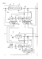
- Fig. 3 is a diagram showing the configuration of power source units and battery units, including a control system, according to an embodiment of the present invention.
- Fig. 3 shows, as a representative example, a case where there is one power source unit and one battery unit, but it is possible to connect two or more of each of these units in a parallel arrangement, similarly to the configuration shown in Fig. 2 .
- 101, 102, 202 respectively indicate a voltage detector
- 103 and 203 respectively indicate a current detector
- 104 and 204 respectively indicate voltage command value setting means
- 105, 106, 205 and 206 respectively indicate an adder.
- 107 and 207 indicate a voltage regulator (Auto Voltage Regulator), which is constituted by a PI (proportional/integral) regulator (Proportional & Integral Regulator), or the like.
- 108, 208 indicate a current regulator (Auto Current Regulator), which is constituted by a PI (proportional/integral) regulator, or the like, similarly to the voltage regulator.
- the output voltage is detected by the voltage detector 102, and a current command value is output by the voltage regulator 107 by finding the differential between the output voltage and the voltage command value from the voltage command value setting means 104.
- the current command value is large when the output voltage is insufficient and is small when the output voltage is excessively large.
- the differential between the current command value and the output current detected by the current detector 103 provided in the power source unit 3 is found, and the internal electromotive force of the DC/DC converter 13 is increased or decreased so as to make the differential approach 0.
- the differential between the current command value output from the voltage adjuster 207 and the output current detected by the current detector 203 provided in the battery unit 6 is found, and the internal electromotive force of the DC/DC converter 19 is increased or decreased so as to make the differential approach zero.
- a limiter (not illustrated) is provided for the current command value when input to the current regulators 108, 208, so as not to output a current exceeding the rated current, irrespective of the load.
- the power source system relating to an embodiment of the present invention uses a plurality of power source units and battery units in a parallel connection arrangement. In this case, control based on the droop characteristics of each unit is implemented in order to achieve a current balance in each of the units.
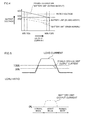
- Fig. 4 is a diagram illustrating the details of droop characteristics relating to an embodiment of the present invention.
- the droop characteristics mean that the output voltage falls in accordance with the output current.
- the output current of a particular unit is large, the current in that unit falls due to narrowing of the voltage as a result of the droop characteristics.
- the output currents of the units become balanced when the full-load current is a value close to the fraction of the parallel number.
- the range of variation of the output voltage due to this is constricted to the range of the output voltage accuracy which is defined by the apparatus specifications.
- the droop characteristics of the battery units 6 to 8 are described further here with reference to Fig. 4 .
- the voltage command value at zero load (indicated by the symbol "VOC” below) is switched between VO1, VO2, VO3 in the battery units 6 to 8 in accordance with the operation mode.
- the output ratings of the power source units 3 to 5 and the battery units 6 to 8 are the same, and the parallel number is the same.
- the rated value of the output current is taken to be 100%.
- the battery units 6 to 8 undertake the whole of the power load, when in the back-up mode. Therefore, the droop characteristics of the battery units 6 to 8 when in the back-up mode are set to be the same as the droop characteristics of the power source units 3 to 5 when in the normal mode (see Fig. 4 , upper part).
- the VOC voltage command value
- VO2 voltage command value
- the output voltage value when the power source units 3 to 5 output 100% current and the output voltage value when the battery units 6 to 8 output 20% current become equal.
- the input current of the load 2 is equivalent to 120% of the rated value
- the output current of the two units is balanced when the power source units 3 to 5 output 100% current, and the battery units 6 to 8 output 20% current, and the system is operated at this ratio. Thereby, unwanted discharging of the battery units 6 to 8 is avoided (see Fig. 4 , middle part).
- the VOC (voltage command value) of the battery units 6 to 8 is reduced to the value VO3, which is lower than the output voltage value when the power source units 3 to 5 output 100% current. Accordingly, it is possible to avoid the occurrence of continuous discharging from the battery units 6 to 8.
- the power source units 3 to 5 deviate from the normal output range due to a sudden change in the load, or the like, then the amount of variation in the voltage can be suppressed by discharge from the battery units 6 to 8 (see Fig. 4 , lower part).
- the current load distribution is adjusted by means of the voltage command value (VOC) at zero load, but it is also possible to adjust the current load by the amount of droop, in other words, the amount of reduction in the output voltage with respect to the output current. Alternatively, it is also possible to adjust the current load distribution by using both the voltage command value (VOC) at zero load and the amount of droop.
- VOC voltage command value
- 109 is power outage detection means which detects an input power outage.
- 110 is assist request generation means which outputs an assist request signal when the current command value in the power source unit is greater than a specific value, for example, the equivalent of 100% output.
- 210 is an assist cancellation request generation means for outputting a signal requesting cancellation of the assist mode when the current command value in the battery unit is lower than a specific value, for instance, 10%.
- the voltage command value setting means 204 sets the VOC (voltage command value) to VO3, and outputs the current command value according to the existing droop settings (see Fig. 4 , lower part).
- the voltage command value setting means 204 sets the VOC (voltage command value) to VO1, regardless of whether or not there is an assist request (see Fig. 4 , upper part).
- the assist request generation means 110 outputs an assist request without the occurrence of a power outage
- the voltage command value setting means 204 sets the VOC (voltage command value) to VO2 (see Fig. 4 , middle part). Therefore, the output from the battery units 6 to 8 is set to a prescribed ratio with respect to a load 2 which exceeds 100% of the rating.
- the fact that the current command value of the power source units 3 to 5 exceeds 100% does not necessarily mean that the input current of the load 2 exceeds 100%.
- the AC/DC conversion units 10 to 12 of the power source units 3 to 5 cannot input current equal to or exceeding a specific level, and therefore the power is insufficient, as a result of which the output voltage falls.
- the voltage regulator 107 of the power source units 3 to 5 increases the current command value in an attempt to restore this voltage fall, and therefore a current exceeding the rating is output (although a current exceeding the rating is not actually output due to the limiter described above). In cases of this kind as well, similarly to the description given above, an assist operation is performed by the battery units 6 to 8, of course.
- the assist cancellation request generation means 210 serves to avoid this situation and, for instance, outputs an assist mode cancellation request signal to the assist request generation means 110, when the output current of the battery units 6 to 8 is lower than 10%.
- the assist request generation means 110 determines that the total load current is equal to or less than 100% and cancels the assist request, when the output current of the host power source unit in this case is lower than 90%.
- the assist mode is maintained (not cancelled), because if the assist mode is cancelled, there is a risk of a current shortage occurring due to current detection errors and/or imbalance between the units.
- Fig. 5 is a diagram showing an operation waveform of a power source system relating to an embodiment of the invention.
- the output current of the power source units 3 to 5 is limited to 100% by the limiter, whereas when the system is in assist mode, the output from the battery units 6 to 8 is applied, as shown in the lower half of Fig. 5 , and a current exceeding 100% is supplied.
- the load current falls below 100%
- the output current of the battery units 6 to 8 falls below 10%
- the output current of the power source units 3 to 5 falls below 90%, and therefore the assist mode is cancelled and all of the load current is supplied from the power source units 3 to 5.
- the simplest method for switching mode when a plurality of power source units 3 to 5 and battery units 6 to 8 are connected in parallel to a DC bus is to adopt a wired OR method, or the like, and interpret that an assist request has been generated when an assist request has been issued by any one of the power source units 3 to 5, and interpret that an assist cancellation request has been generated when all of the battery units 6 to 8 have issued an assist cancellation request.
- Each unit outputs an assist request or assist cancellation request using a current command value, but may also output an assist request or assist cancellation request using an output current.
- a continuous amount such as current or voltage
- the present invention can be applied to a power source apparatus for a communications apparatus or a power source apparatus for a large-scale computer.
Landscapes
- Engineering & Computer Science (AREA)
- Power Engineering (AREA)
- Business, Economics & Management (AREA)
- Emergency Management (AREA)
- Charge And Discharge Circuits For Batteries Or The Like (AREA)
- Supply And Distribution Of Alternating Current (AREA)
- Power Sources (AREA)
- Stand-By Power Supply Arrangements (AREA)
- Dc-Dc Converters (AREA)
Priority Applications (1)
| Application Number | Priority Date | Filing Date | Title |
|---|---|---|---|
| EP16200235.6A EP3176897B1 (de) | 2013-07-30 | 2013-07-30 | Stromquellensystem |
Applications Claiming Priority (1)
| Application Number | Priority Date | Filing Date | Title |
|---|---|---|---|
| PCT/JP2013/070644 WO2015015570A1 (ja) | 2013-07-30 | 2013-07-30 | 電源システム |
Related Child Applications (2)
| Application Number | Title | Priority Date | Filing Date |
|---|---|---|---|
| EP16200235.6A Division EP3176897B1 (de) | 2013-07-30 | 2013-07-30 | Stromquellensystem |
| EP16200235.6A Division-Into EP3176897B1 (de) | 2013-07-30 | 2013-07-30 | Stromquellensystem |
Publications (2)
| Publication Number | Publication Date |
|---|---|
| EP2955828A1 true EP2955828A1 (de) | 2015-12-16 |
| EP2955828A4 EP2955828A4 (de) | 2017-01-11 |
Family
ID=52431151
Family Applications (2)
| Application Number | Title | Priority Date | Filing Date |
|---|---|---|---|
| EP16200235.6A Not-in-force EP3176897B1 (de) | 2013-07-30 | 2013-07-30 | Stromquellensystem |
| EP13890645.8A Withdrawn EP2955828A4 (de) | 2013-07-30 | 2013-07-30 | Leistungsversorgungssystem |
Family Applications Before (1)
| Application Number | Title | Priority Date | Filing Date |
|---|---|---|---|
| EP16200235.6A Not-in-force EP3176897B1 (de) | 2013-07-30 | 2013-07-30 | Stromquellensystem |
Country Status (5)
| Country | Link |
|---|---|
| US (1) | US9882379B2 (de) |
| EP (2) | EP3176897B1 (de) |
| JP (1) | JP6123896B2 (de) |
| CN (1) | CN105027404B (de) |
| WO (1) | WO2015015570A1 (de) |
Cited By (3)
| Publication number | Priority date | Publication date | Assignee | Title |
|---|---|---|---|---|
| WO2018006593A1 (zh) * | 2016-07-06 | 2018-01-11 | 中兴通讯股份有限公司 | Wifi的供电切换方法、电路及装置、存储介质 |
| EP3301772A1 (de) * | 2016-09-29 | 2018-04-04 | Hewlett-Packard Enterprise Development LP | Stromversorgung mit logikschaltung |
| CN109196761A (zh) * | 2016-06-02 | 2019-01-11 | 株式会社村田制作所 | 电源系统 |
Families Citing this family (24)
| Publication number | Priority date | Publication date | Assignee | Title |
|---|---|---|---|---|
| JP6693179B2 (ja) * | 2015-04-01 | 2020-05-13 | 富士電機株式会社 | 電源装置 |
| JP6532285B2 (ja) * | 2015-05-13 | 2019-06-19 | 株式会社Nttドコモ | 整流装置 |
| WO2016189976A1 (ja) * | 2015-05-25 | 2016-12-01 | 富士電機株式会社 | 無停電電源装置および該装置の制御方法 |
| WO2017064801A1 (ja) * | 2015-10-15 | 2017-04-20 | 富士電機株式会社 | 電源システムおよび該システムにおけるパワーアシスト開始点の再設定方法 |
| WO2017125067A1 (en) * | 2016-01-22 | 2017-07-27 | The University Of Hong Kong | Power supply supporting virtual inertia for grid control (micro-spring converter) |
| JP6807156B2 (ja) * | 2016-01-29 | 2021-01-06 | コイト電工株式会社 | 電源システム及び鉄道用車両 |
| WO2017150141A1 (ja) * | 2016-02-29 | 2017-09-08 | 株式会社 村田製作所 | 電源制御システム、電源制御方法および電源制御プログラム |
| WO2017209238A1 (ja) * | 2016-06-02 | 2017-12-07 | 株式会社村田製作所 | バッテリモジュール電圧制御装置、バッテリモジュールおよび電源システム |
| US10840813B2 (en) * | 2016-06-02 | 2020-11-17 | Mitsubishi Electric Corporation | Power conversion system |
| CN106292982A (zh) * | 2016-08-12 | 2017-01-04 | 浪潮(北京)电子信息产业有限公司 | 一种数据中心能耗控制系统及方法 |
| JP2018137893A (ja) * | 2017-02-22 | 2018-08-30 | 富士電機株式会社 | 電源装置 |
| JP6922449B2 (ja) | 2017-06-08 | 2021-08-18 | 富士電機株式会社 | 電源システムおよび電源装置 |
| JP6835676B2 (ja) * | 2017-07-05 | 2021-02-24 | 株式会社ダイヘン | 電源システム、電源装置、制御方法及び制御プログラム |
| CN110323734B (zh) * | 2018-03-29 | 2024-06-18 | 雅达电子国际有限公司 | 用于具有多个电源的电力系统的优先级负载分担 |
| JP7152892B2 (ja) * | 2018-07-19 | 2022-10-13 | ニチコン株式会社 | 直流給電システム |
| TWI690129B (zh) * | 2018-11-29 | 2020-04-01 | 國家中山科學研究院 | 使用電流內迴路調整之再生能源發電及儲能系統 |
| CN111404399B (zh) * | 2019-01-03 | 2021-11-02 | 台达电子工业股份有限公司 | 供电系统 |
| JP2020120465A (ja) * | 2019-01-22 | 2020-08-06 | 株式会社Nttファシリティーズ | 電力変換システム |
| JP7203325B2 (ja) * | 2019-05-20 | 2023-01-13 | パナソニックIpマネジメント株式会社 | 電力システム |
| US10862712B1 (en) * | 2019-06-17 | 2020-12-08 | Savant Systems, Inc. | Battery-assisted power-over-ethernet powered device |
| CN112436768B (zh) * | 2020-11-12 | 2022-09-09 | 漳州科华技术有限责任公司 | 一种车载变换器的控制方法、系统、装置及车载变换器 |
| US20240007327A1 (en) * | 2021-01-27 | 2024-01-04 | Sansha Electric Manufacturing Co., Ltd. | Power supply system and power supply unit |
| EP4451510A1 (de) * | 2023-04-21 | 2024-10-23 | Nexans | Ersatzteilsystem zur aufrechterhaltung der verfügbarkeit von ersatzteilen für ein stromversorgungssystem |
| TW202524803A (zh) * | 2023-08-25 | 2025-06-16 | 新加坡商偉創力有限公司 | 電力系統及處理尖峰負載之控制方法 |
Family Cites Families (12)
| Publication number | Priority date | Publication date | Assignee | Title |
|---|---|---|---|---|
| JPH09103032A (ja) * | 1995-10-04 | 1997-04-15 | Furukawa Battery Co Ltd:The | 直流電源装置 |
| WO2002061917A1 (en) * | 2001-02-01 | 2002-08-08 | Hitachi Maxell, Ltd. | Power supply |
| JP3947906B2 (ja) * | 2001-08-30 | 2007-07-25 | 株式会社日立製作所 | バックアップ電源と電源装置 |
| JP2005168090A (ja) * | 2003-11-28 | 2005-06-23 | Tdk Corp | 並列駆動型電源装置 |
| JP2005168107A (ja) * | 2003-11-28 | 2005-06-23 | Tdk Corp | 並列駆動型電源装置 |
| US7394674B2 (en) * | 2004-12-28 | 2008-07-01 | Zippy Technology Corp. | Backup power supply with parallel AC power source and DC power source |
| JP4784652B2 (ja) * | 2008-02-26 | 2011-10-05 | パナソニック電工株式会社 | 電源供給装置 |
| JP5420433B2 (ja) * | 2010-01-14 | 2014-02-19 | ルネサスエレクトロニクス株式会社 | 半導体装置および電源装置 |
| JP5730133B2 (ja) * | 2011-06-03 | 2015-06-03 | Fdk株式会社 | 直流給電装置 |
| JP2013013176A (ja) * | 2011-06-28 | 2013-01-17 | Mitsubishi Electric Corp | 自立電源装置 |
| JP5746928B2 (ja) | 2011-08-23 | 2015-07-08 | 株式会社Nttファシリティーズ | 直流電源装置 |
| JP6008040B2 (ja) * | 2013-03-15 | 2016-10-19 | 富士電機株式会社 | 無停電電源装置 |
-
2013
- 2013-07-30 JP JP2015529255A patent/JP6123896B2/ja active Active
- 2013-07-30 EP EP16200235.6A patent/EP3176897B1/de not_active Not-in-force
- 2013-07-30 EP EP13890645.8A patent/EP2955828A4/de not_active Withdrawn
- 2013-07-30 WO PCT/JP2013/070644 patent/WO2015015570A1/ja not_active Ceased
- 2013-07-30 CN CN201380074343.6A patent/CN105027404B/zh active Active
-
2015
- 2015-09-04 US US14/846,627 patent/US9882379B2/en not_active Expired - Fee Related
Cited By (6)
| Publication number | Priority date | Publication date | Assignee | Title |
|---|---|---|---|---|
| CN109196761A (zh) * | 2016-06-02 | 2019-01-11 | 株式会社村田制作所 | 电源系统 |
| EP3447892A4 (de) * | 2016-06-02 | 2019-11-20 | Murata Manufacturing Co., Ltd. | Stromversorgungssystem |
| WO2018006593A1 (zh) * | 2016-07-06 | 2018-01-11 | 中兴通讯股份有限公司 | Wifi的供电切换方法、电路及装置、存储介质 |
| CN107592205A (zh) * | 2016-07-06 | 2018-01-16 | 中兴通讯股份有限公司 | Wifi的供电切换方法、电路及装置 |
| EP3301772A1 (de) * | 2016-09-29 | 2018-04-04 | Hewlett-Packard Enterprise Development LP | Stromversorgung mit logikschaltung |
| US10819139B2 (en) | 2016-09-29 | 2020-10-27 | Hewlett Packard Enterprise Development Lp | Power supply including logic circuit |
Also Published As
| Publication number | Publication date |
|---|---|
| WO2015015570A1 (ja) | 2015-02-05 |
| CN105027404B (zh) | 2018-03-30 |
| EP3176897A1 (de) | 2017-06-07 |
| CN105027404A (zh) | 2015-11-04 |
| JPWO2015015570A1 (ja) | 2017-03-02 |
| US20160006242A1 (en) | 2016-01-07 |
| EP3176897B1 (de) | 2020-11-18 |
| JP6123896B2 (ja) | 2017-05-10 |
| EP2955828A4 (de) | 2017-01-11 |
| US9882379B2 (en) | 2018-01-30 |
Similar Documents
| Publication | Publication Date | Title |
|---|---|---|
| US9882379B2 (en) | Power source system | |
| EP2670015B1 (de) | Leistungsregelungsvorrichtung und leistungsregelungsverfahren | |
| EP3190682B1 (de) | Stromversorgungssysteme und verfahren | |
| EP3301772B1 (de) | Stromversorgung mit logikschaltung | |
| US9893561B2 (en) | Power supply conversion system and method of controlling the same | |
| JP4318123B2 (ja) | バックアップ電源及び電源装置 | |
| US10003200B2 (en) | Decentralized module-based DC data center | |
| US8203235B2 (en) | AC and DC uninterruptible online power supplies | |
| JP2008545368A (ja) | 並列upsシステムにおける最大バッテリー稼動時間 | |
| WO2010076076A1 (en) | Reducing power consumption on devices with multiple power supplies | |
| US11984759B2 (en) | Grid ancillary service with uninterruptible power supply | |
| KR101538232B1 (ko) | 배터리 관리 장치 및 이를 포함하는 배터리 에너지 저장 시스템 | |
| US20130314959A1 (en) | Control arrangement and method for regulating the output voltage of a dc source power converter connected to a multi-source dc system | |
| CN102214945A (zh) | 一种基于蓄电池并联的直流电源系统 | |
| US20140082393A1 (en) | Hot Swapping Type Uninterruptible Power Supply Module | |
| JP2013247795A (ja) | 分散型電源の自立運転システム | |
| KR102233773B1 (ko) | 전력 변환 시스템 및 그의 제어 방법 | |
| JP5730133B2 (ja) | 直流給電装置 | |
| CA3108816C (en) | Method for controlling electrical consumers of an electrical supply grid | |
| CN105576642A (zh) | 监视功率系统功率变换器的系统和方法 | |
| CN114637357A (zh) | 故障检测方法、控制器、旁路稳压电路及存储介质 | |
| WO2016152177A1 (ja) | 蓄電システム | |
| TWI408865B (zh) | 不斷電電源供應器及其所適用之電源供應方法 | |
| US11258297B2 (en) | Inverter control strategy for a transient heavy load | |
| JP6760474B1 (ja) | 分散型電源システム |
Legal Events
| Date | Code | Title | Description |
|---|---|---|---|
| PUAI | Public reference made under article 153(3) epc to a published international application that has entered the european phase |
Free format text: ORIGINAL CODE: 0009012 |
|
| 17P | Request for examination filed |
Effective date: 20150907 |
|
| AK | Designated contracting states |
Kind code of ref document: A1 Designated state(s): AL AT BE BG CH CY CZ DE DK EE ES FI FR GB GR HR HU IE IS IT LI LT LU LV MC MK MT NL NO PL PT RO RS SE SI SK SM TR |
|
| AX | Request for extension of the european patent |
Extension state: BA ME |
|
| RIC1 | Information provided on ipc code assigned before grant |
Ipc: H02J 9/00 20060101ALI20160822BHEP Ipc: H02J 7/34 20060101ALI20160822BHEP Ipc: H02J 1/10 20060101AFI20160822BHEP |
|
| DAX | Request for extension of the european patent (deleted) | ||
| A4 | Supplementary search report drawn up and despatched |
Effective date: 20161209 |
|
| RIC1 | Information provided on ipc code assigned before grant |
Ipc: H02J 7/34 20060101ALI20161202BHEP Ipc: H02J 9/00 20060101ALI20161202BHEP Ipc: H02J 1/10 20060101AFI20161202BHEP |
|
| STAA | Information on the status of an ep patent application or granted ep patent |
Free format text: STATUS: EXAMINATION IS IN PROGRESS |
|
| 17Q | First examination report despatched |
Effective date: 20190408 |
|
| STAA | Information on the status of an ep patent application or granted ep patent |
Free format text: STATUS: THE APPLICATION HAS BEEN WITHDRAWN |
|
| 18W | Application withdrawn |
Effective date: 20190807 |