EP2956074B1 - Éléments de compression de verrouillage pour utilisation avec des ensembles d'ancrage osseux - Google Patents
Éléments de compression de verrouillage pour utilisation avec des ensembles d'ancrage osseux Download PDFInfo
- Publication number
- EP2956074B1 EP2956074B1 EP14714480.2A EP14714480A EP2956074B1 EP 2956074 B1 EP2956074 B1 EP 2956074B1 EP 14714480 A EP14714480 A EP 14714480A EP 2956074 B1 EP2956074 B1 EP 2956074B1
- Authority
- EP
- European Patent Office
- Prior art keywords
- receiver member
- bone anchor
- compression cap
- wings
- anchor assembly
- Prior art date
- Legal status (The legal status is an assumption and is not a legal conclusion. Google has not performed a legal analysis and makes no representation as to the accuracy of the status listed.)
- Active
Links
Images





Classifications
-
- A—HUMAN NECESSITIES
- A61—MEDICAL OR VETERINARY SCIENCE; HYGIENE
- A61B—DIAGNOSIS; SURGERY; IDENTIFICATION
- A61B17/00—Surgical instruments, devices or methods
- A61B17/56—Surgical instruments or methods for treatment of bones or joints; Devices specially adapted therefor
- A61B17/58—Surgical instruments or methods for treatment of bones or joints; Devices specially adapted therefor for osteosynthesis, e.g. bone plates, screws or setting implements
- A61B17/68—Internal fixation devices, including fasteners and spinal fixators, even if a part thereof projects from the skin
- A61B17/70—Spinal positioners or stabilisers, e.g. stabilisers comprising fluid filler in an implant
- A61B17/7001—Screws or hooks combined with longitudinal elements which do not contact vertebrae
- A61B17/7035—Screws or hooks, wherein a rod-clamping part and a bone-anchoring part can pivot relative to each other
- A61B17/7037—Screws or hooks, wherein a rod-clamping part and a bone-anchoring part can pivot relative to each other wherein pivoting is blocked when the rod is clamped
-
- A—HUMAN NECESSITIES
- A61—MEDICAL OR VETERINARY SCIENCE; HYGIENE
- A61B—DIAGNOSIS; SURGERY; IDENTIFICATION
- A61B17/00—Surgical instruments, devices or methods
- A61B17/56—Surgical instruments or methods for treatment of bones or joints; Devices specially adapted therefor
- A61B17/58—Surgical instruments or methods for treatment of bones or joints; Devices specially adapted therefor for osteosynthesis, e.g. bone plates, screws or setting implements
- A61B17/68—Internal fixation devices, including fasteners and spinal fixators, even if a part thereof projects from the skin
- A61B17/70—Spinal positioners or stabilisers, e.g. stabilisers comprising fluid filler in an implant
- A61B17/7001—Screws or hooks combined with longitudinal elements which do not contact vertebrae
- A61B17/7032—Screws or hooks with U-shaped head or back through which longitudinal rods pass
-
- A—HUMAN NECESSITIES
- A61—MEDICAL OR VETERINARY SCIENCE; HYGIENE
- A61B—DIAGNOSIS; SURGERY; IDENTIFICATION
- A61B17/00—Surgical instruments, devices or methods
- A61B17/56—Surgical instruments or methods for treatment of bones or joints; Devices specially adapted therefor
- A61B17/58—Surgical instruments or methods for treatment of bones or joints; Devices specially adapted therefor for osteosynthesis, e.g. bone plates, screws or setting implements
- A61B17/68—Internal fixation devices, including fasteners and spinal fixators, even if a part thereof projects from the skin
- A61B17/70—Spinal positioners or stabilisers, e.g. stabilisers comprising fluid filler in an implant
- A61B17/7001—Screws or hooks combined with longitudinal elements which do not contact vertebrae
- A61B17/7035—Screws or hooks, wherein a rod-clamping part and a bone-anchoring part can pivot relative to each other
-
- A—HUMAN NECESSITIES
- A61—MEDICAL OR VETERINARY SCIENCE; HYGIENE
- A61B—DIAGNOSIS; SURGERY; IDENTIFICATION
- A61B17/00—Surgical instruments, devices or methods
- A61B2017/00477—Coupling
-
- A—HUMAN NECESSITIES
- A61—MEDICAL OR VETERINARY SCIENCE; HYGIENE
- A61B—DIAGNOSIS; SURGERY; IDENTIFICATION
- A61B17/00—Surgical instruments, devices or methods
- A61B2017/00526—Methods of manufacturing
Definitions
- the present invention relates to devices for correcting a spine, and in particular to bone anchor assemblies.
- Bone anchors may be used in orthopedic surgery to fix bone during healing or during a fusion process.
- spinal surgery bone anchors may be used with spinal fixation elements, such as spinal rods, to stabilize multiple vertebrae either rigidly, in which no relative motion between the vertebrae is desired, or dynamically, in which limited, controlled motion between the vertebrae is desired.
- Fixation elements can help to support the spine in a desired alignment, for example by defining a shape towards which a deformed spine is to be corrected. Attaching the vertebrae to the fixation element causes vertebrae which are out of position to be drawn towards the fixation element, so that they can then be retained in a correct alignment against forces imposed by soft tissue tending to revert the configuration of the spine towards the deformed shape. Correction of the spinal deformation can involve application to the vertebrae of translational forces, torsional forces, or combinations thereof to cause vertebrae to translate and/or rotate.
- Surgical procedures using bone anchors often require that the bone anchor be secured to the bone at a predetermined angle to a surface of the bone.
- Traditional bone anchors can include a shaft having a spherical head that is polyaxially seated in a receiver member and that can be secured at a fixed angle to the receiver member by a compression member.
- traditional methods can require deformation of the receiver member against the compression cap. The deformation process, called "swaging,” compresses the receiver member against the compression cap to substantially prevent relative movement therebetween.
- the swaging process can weaken the structure of the bone anchor and can increase the expense and the time required for manufacturing of the bone anchor.
- US Patent Publication No. US-2012/0150239 discloses a poly-axial pedicle screw assembly which includes a tulip-like coupling element that can be coupled to a fixation element in the form of a screw with a head that removably mates with the coupling element.
- the coupling element and fixation element are configured to be coupled to an elongate stabilizer, in the form of a rod, that is positioned between a top and a bottom saddle or between a compression member and bottom saddle.
- a compression member, in the form of a compression nut is configured to mate with the coupling element and provides a compressive force to the top and bottom saddles or to the top of the elongate stabilizer rod to secure the elongate stabilizer rod therebetween.
- the top and bottom saddles are movably positioned within the coupling element such that they can reposition into a secure engagement with the stabilizer as the compression member provides the compressive force.
- the bottom saddle has an internal bore that axially aligns with a bore in the coupling element when the bottom saddle is placed in the coupling element.
- the bottom saddle has a cylindrical outer surface forming a pair of opposed walls separated by the internal bore and a rod-receiving region. Outer surfaces of the opposed walls include opposing projections that extend laterally from the walls. Each of the projections aligns with a corresponding hole or aperture that extends through the coupling element.
- US Patent Publication No. US-2010/0160977 discloses a coupling device for securing an elongate member to the spine.
- the coupling device comprises a compressible inner member that secures an anchor member therein when the inner member is axially shifted within an outer member.
- the elongate member is retained within the device by an axially inserted locking member, and may be secured independently of the anchor member.
- the coupling device and anchor may be configured to provide increased angulation of the anchor with respect to the coupling device.
- US Patent Publication No. US-2012/0209336 discloses a polyaxial bone screw assembly including a threaded shank body having an integral upper portion receivable in an integral receiver, the receiver having an upper channel for receiving a longitudinal connecting member and a lower cavity cooperating with a lower opening.
- a down-loadable compression insert with tool receiving arm extensions, a down-loadable friction fit split retaining ring and an up-loadable shank upper portion cooperate to provide for pop- or snap-on assembly of the shank with the receiver either prior to or after implantation of the shank into a vertebra.
- EP-2286748 discloses a bone anchoring device which includes an anchoring element having a shaft for anchoring in the bone and a head; a receiving part formed in one piece, the receiving part having a seat for receiving the head and a channel for receiving a rod to be connected to the anchoring element; and a pressure element formed in one piece, the pressure element being movable in the receiving part so as to be able to exert pressure onto the head.
- the anchoring element is pivotable with respect to the receiving part and can be fixed at an angle by exerting pressure via the pressure element onto the head.
- the pressure element comprises a spring element which engages a portion of the receiving part so that the pressure element can be held in a position which allows pivoting of the anchoring element.
- the present invention provides a bone anchor assembly as claimed in claim 1.
- the bone anchor assembly which may be a bone screw assembly, includes a bone anchor, which may be a bone screw, having a proximal portion and a distal shank portion, a receiver member having a polyaxial seat formed therein and configured to proximally seat the head portion of the screw, and a compression cap.
- the compression cap can be disposed within the receiver member and has a distal end configured to engage the head portion of the anchor (optionally a bone screw).
- Opposed projections of the compression cap in the form of opposed wings, extend radially therefrom and are configured to mate with complementary recesses, in the form of pockets, formed in the receiver member such that the compression cap is retained within the receiver member.
- the opposed projections can be configured in a number of ways.
- a distance between outer surfaces of the opposed projections can be greater than the inside diameter of the receiver member, although the compression cap can have an outside diameter that is less than an inside diameter of the receiver member.
- a width of each projection measured horizontally about the circumference of the compression cap can be greater than a thickness of the opposed projection measured along a radial axis of the compression cap.
- the opposed projections can be configured such that movement of the compression cap distally within the receiver member is effective to deform the opposed projections until the opposed projections snap into engagement with the complementary recesses.
- Rotating the compression cap relative to the receiver member can also be effective to deform the opposed projections until the opposed projections snap into engagement with the complementary recesses, and/or can be effective to move the opposed projections into engagement with the complementary recesses.
- the opposed projections and the complementary recesses can be effective, when mated, to maintain the compression cap in a substantially fixed longitudinal and/or rotational position relative to the receiver member.
- a proximal-facing surface of each projection and an inner superior surface of each complementary recess can be planar such that, when mated, the compression cap is prevented from being decoupled from the receiver member.
- a distal-facing surface of each projection can be ramped, tapered, chamfered, and/or beveled to provide a lead-in surface geometry.
- the receiver member includes shoulders disposed proximal to the complementary recesses, the shoulders being ramped to provide a lead-in surface for the opposed projections as the compression cap is advanced distally relative to the receiver member.
- the complementary recesses may comprise cut-outs formed in a shelf that extends radially inward from an interior sidewall of the receiver member, and the shelf can include one or more lateral edges that are ramped, tapered, chamfered, and/or beveled to provide a lead-in surface for the opposed projections.
- a method for assembling a bone screw is disclosed, which does not fall within the scope of the invention as claimed.
- the method can include passing a shank portion of the bone screw through an aperture formed in a distal end of a receiver member, inserting a compression cap into the receiver member, and engaging opposed projections extending radially outward from the compression cap with complementary recesses formed in the receiver member to retain the compression cap within the receiver member.
- the method can further include deforming the projections over a shoulder portion of the receiver member disposed proximal to the complementary recesses.
- the engaging can be effective to maintain the compression cap in a substantially fixed longitudinal and/or rotational position relative to the receiver member.
- Inserting the compression cap can comprise sliding the compression cap distally within the receiver member to deform the opposed projections until the opposed rejections snap into engagement with the complementary recesses. Inserting the compression cap can also comprise rotating the compression cap relative to the receiver member to move the opposed projections into engagement with the complementary recesses.
- the complementary recesses can be formed in a shelf that extends radially inward from an interior sidewall of the receiver member
- the engaging can comprise camming the opposed projections over ramped, tapered, chamfered, and/or beveled edges of the shelf and snapping the opposed projections into the complementary recesses.
- a bone anchor assembly includes a bone anchor configured to engage bone, a receiver member for seating a head of the bone anchor, and a compression member for securing the receiver member at fixed angle with respect to the bone anchor.
- the compression member can be seated within the receiver member, proximally of the head of the bone anchor, and can include one or more engagement features to facilitate attachment to the receiver member.
- the receiver member can include one or more complementary engagement features that correspond to the engagement features of the compression member.
- Mating between the corresponding engagement features of the compression member and the receiver member in a secured configuration can be sufficient to inhibit or prevent removal of the compression member from the receiver member, thus reducing a risk of accidental loss or misplacement of the compression member.
- Engagement of the corresponding engagement features can optionally be sufficient to substantially prevent longitudinal and/or rotational movement of the compression member with respect to the receiver member, such that once the compression member is in the secured configuration, the compression member can exert a distal force on the head of the bone anchor and can substantially fix the bone anchor at the desired angle with respect to the receiver member.
- FIGS. 1A-1D illustrate a prior art bone anchor assembly 10 that includes a bone anchor 12, a receiver member 14 for receiving a spinal fixation element, such as a spinal rod 22, to be coupled to the bone anchor 12, and a closure mechanism 16 to capture a spinal fixation element within the receiver member 14 and fix the spinal fixation element with respect to the receiver member 14.
- the bone anchor 12 includes a proximal head 18 and a distal shaft 20 configured to engage bone.
- the receiver member 14 has a proximal end 26 having a pair of spaced apart arms 28A, 28B defining a recess 30 therebetween and a distal end 32 having a distal end surface 34 defining an opening through which at least a portion of the bone anchor 12 extends.
- the closure mechanism 16 can be positionable between and can engage the arms 28A, 28B to capture a spinal fixation element, e.g., a spinal rod 22, within the receiver member 14 and fix the spinal fixation element with respect to the receiver member 14.
- the proximal head 18 of the bone anchor 12 is generally in the shape of a truncated sphere having a planar proximal surface 36 and an approximately spherically-shaped distal surface 38.
- the illustrated bone anchor assembly is a polyaxial bone screw designed for posterior implantation in the pedicle or lateral mass of a vertebra.
- the proximal head 18 of the bone anchor 12 engages the distal end 32 of the receiver member 14 in a ball and socket like arrangement in which the proximal head 18 and the distal shaft 20 can pivot relative to the receiver member 14.
- the distal surface 38 of the proximal head 18 of the bone anchor 12 and a mating surface within the distal end 32 of the receiver member 14 can have any shape that facilitates this arrangement, including, for example, spherical (as illustrated), toroidal, conical, frustoconical, and any combinations of these shapes.
- the distal shaft 20 of the bone anchor 12 can be configured to engage bone and, in the illustrated embodiment, includes an external bone engaging thread 40.
- the thread form for the distal shaft 20, including the number of threads, the pitch, the major and minor diameters, and the thread shape, can be selected to facilitate connection with bone. Exemplary thread forms are disclosed in U.S. Patent Application Publication No. 2011/0288599, filed on May 18, 2011 , and in U.S. Publication No. 2013/0053901 , filed August 25, 201 ( US patent number US9155580 ) 1
- the distal shaft 20 can also include other structures for engaging bone, including a hook.
- the distal shaft 20 of the bone anchor 12 can be cannulated, having a central passage or cannula extending the length of the bone anchor to facilitate delivery of the bone anchor over a guide wire in, for example, minimally-invasive procedures.
- Other components of the bone anchor assembly 10, including, for example, the closure mechanism 16, the receiver member 14, and the compression member 60 (discussed below) can be cannulated or otherwise have an opening to permit delivery over a guide wire.
- the distal shaft 20 can also include one or more sidewall openings or fenestrations that communicate with the cannula to permit bone ingrowth or to permit the dispensing of bone cement or other materials through the bone anchor 12. The sidewall openings can extend radially from the cannula through the sidewall of the distal shaft 20.
- Exemplary systems for delivering bone cement to the bone anchor assembly 10 and alternative bone anchor configurations for facilitating cement delivery are described in U.S. Patent Application Publication No. 2010/0114174, filed on October 29, 2009 ( US patent number US9265548 ).
- the distal shaft 20 of the bone anchor 12 can also be coated with materials to permit bone growth, such as, for example, hydroxyl apatite, and the bone anchor assembly 10 can be coated partially or entirely with anti-infective materials, such as, for example, tryclosan.
- the proximal end 26 of the receiver member 14 includes a pair of spaced apart arms 28A, 28B defining a U-shaped recess 30 therebetween for receiving a spinal fixation element, e.g., a spinal rod 22.
- Each of the arms 28A, 28B can extend from the distal end 32 of the receiver member 14 to a free end.
- the arms 28A, 28B can include a feature, such as a bore, recess, dimple, notch, projection, or the like, to facilitate connection of the receiver member 14 to instruments,
- opposing bores 80A, 80B are formed on the arms 28A, 28B for insertion of two pins as part of a swaging process, described in more detail below.
- each arm 28A, 28B can further include an arcuate groove at the respective free end of the arms. Such grooves are described in more detail in U.S. Patent No. 7,179,261, issued on February 20, 2007 . At least a portion of the proximal end surface 48 of the receiver member 14 defines a plane Y.
- the receiver member 14 has a central longitudinal axis L.
- the distal end 32 of the receiver member 14 includes a distal end surface 34 which is generally annular in shape defining a circular opening through which at least a portion of the bone anchor 12 extends.
- a distal end surface 34 which is generally annular in shape defining a circular opening through which at least a portion of the bone anchor 12 extends.
- the distal shaft 20 of the bone anchor 12 can extend through the opening.
- At least a portion of the distal end surface 34 defines a plane X.
- the bone anchor 12 can be selectively fixed relative to the receiver member 14. Prior to fixation, the bone anchor 12 is movable relative to the receiver member 14 within a cone of angulation generally defined by the geometry of the distal end 32 of the receiver member and the proximal head 18 of the bone anchor 12.
- the illustrated bone anchor is a favored-angle polyaxial screw in which the cone of angulation is biased in one direction. In this manner, the bone anchor 12 is movable relative to the receiver member 14 in at least a first direction, indicated by arrow A in FIG. 1D , at a first angle C relative to the central longitudinal axis L of the receiver member 14.
- the bone anchor 12 is also movable in at least a second direction, indicated by arrow B in FIG.
- the distal shaft 20 of the bone anchor 12 defines a neutral axis 48 with respect to the receiver member 14.
- the neutral axis 48 can be perpendicular to the plane X defined by the distal end surface 34 and intersects the center point of the opening in the distal end surface 34 through which the distal shaft 20 of the bone anchor 12 extends.
- the neutral axis 48 can be oriented at an angle to the central longitudinal axis L of the receiver member 14.
- the proximal end 26 of the receiver member 14 can include a proximal first bore 50 coaxial with a first central longitudinal axis N (which is coincident with longitudinal axis L) and a distal second bore 52 coaxial with a second central longitudinal axis M (which is coincident with the neutral axis 48) and the first central longitudinal axis N and second central longitudinal axis M can intersect one another.
- the angle between the plane X and the plane Y and the angle between the axis L and the axis M can be selected to provide the desired degree of biased angulation.
- Examples of favored angled polyaxial screws are described in more detail in U.S. Patent No. 6,974,460, issued on December 13, 2005 , and in U.S. Patent No. 6,736,820, issued on May 18, 2004 .
- the bone anchor assembly can be a conventional (non-biased) polyaxial screw in which the bone anchor pivots in the same amount in every direction and has a neutral axis that is coincident with the central longitudinal axis L of the receiver member.
- the spinal fixation element e.g., the spinal rod 22
- the spinal fixation element can either directly contact the proximal head 18 of the bone anchor 12 or can contact an intermediate element, e.g., a compression member 60.
- the compression member 60 can be positioned within the receiver member 14 and interposed between the spinal rod 22 and the proximal head 18 of the bone anchor 12 to compress the distal outer surface 38 of the proximal head 18 into direct, fixed engagement with the distal inner surface of the receiver member 14.
- the compression member 60 can include a pair of spaced apart arms 62A and 62B defining a U-shaped seat 64 for receiving the spinal rod 22 and a distal surface 66 for engaging the proximal head 18 of the bone anchor 12.
- a largest diameter of the compression member 60 can be smaller than a smallest inner diameter of the receiver member 14 to allow the compression member 60 to fit within the recess 30 of the receiver member 14.
- the compression member 60 is configured to slide freely along the longitudinal axis L within the slot 30 of the receiver member 14.
- the compression member 60 is configured to be mechanically deformed against the receiver member 14.
- Opposing bores 68A, 68B formed on the arms 62A, 62B of the compression member 60 are aligned with the bores 80A, 80B of the receiver member 14, such that opposing pins can be inserted through the passageways defined by bores 68A, 80A and bores 68B, 80B to compress or "swage" the compression member 60 against the receiver member 14.
- the swaging process can prevent subsequent removal of the compression member 60 from the receiver member 14.
- the proximal end 26 of the receiver member 14 can be configured to receive a closure mechanism 16 positionable between and engaging the arms 28A, 28B of the receiver member 14.
- the closure mechanism 16 can be configured to capture a spinal fixation element, e.g., a spinal rod 22, within the receiver member 14, to fix the spinal rod 22 relative to the receiver member 14, and to fix the bone anchor 12 relative to the receiver member 14.
- the closure mechanism 16 can be a single set screw having an outer thread for engaging an inner thread 42 provided on the arms 28A, 28B of the receiver member 14. In the illustrated embodiment, however, the closure mechanism 16 comprises an outer set screw 70 positionable between and engaging the arms 28A, 28B of the receiver member 14 and an inner set screw 72 positionable within the outer set screw 70.
- the outer set screw 70 is operable to act on the compression member 60 to fix the bone anchor 12 relative to the receiver member 14.
- the inner set screw 72 is operable to act on the spinal rod 22 to fix the spinal rod 22 relative to the receiver member 14.
- the closure mechanism 16 permits the bone anchor 12 to be fixed relative to the receiver member 14 independently of the spinal rod 22 being fixed to the receiver member 14.
- the outer set screw 70 can engage the proximal end surfaces of the arms 62A, 62B of the compression member 60 to force the distal surface 66 of the compression member 60 into contact with the proximal head 18 of bone anchor 12, which in turn forces the distal surface 38 of the proximal head 18 into fixed engagement with the distal inner surface of the receiver member 14.
- the inner set screw 72 can engage the spinal rod 22 to force the spinal rod 22 into fixed engagement with the rod seat 64 of the compression member 60.
- the outer set screw 70 includes a first outer thread 74 for engaging a complementary inner thread 42 on the arms 28A, 28B of the receiver member 14.
- the outer set screw 74 includes a central passage 96 from a top surface 98 of the outer set screw 74 to a bottom surface 100 of the outer set screw 74 for receiving the inner set screw 72.
- the central passage 96 can includes an inner thread 102 for engaging a complementary outer thread 104 on the inner set screw 72.
- the thread form for the inner thread 102 and the outer thread 104 including the number of threads, the pitch, major and minor diameter, and thread shape, can be selected to facilitate connection between the components and transfer of the desired axial tightening force.
- the top surface 98 of the outer set screw 74 can have one or more drive features to facilitate rotation and advancement of the outer set screw 74 relative to the receiver member 14.
- the illustrated outer set screw 74 includes drive features in the form of a plurality of cut-outs 106 spaced-apart about the perimeter of the top surface 98.
- the inner set screw 72 can include drive features for receiving an instrument to rotate and advance the inner set screw 72 relative to the outer set screw 74.
- the illustrated inner set screw 72 includes drive features in the form of a central passage 108 having a plurality of spaced apart, longitudinally oriented cut-outs for engaging complementary features on an instrument.
- the bone anchor assembly 10 can be used with a spinal fixation element such as rigid spinal rod 22.
- a spinal fixation element such as rigid spinal rod 22.
- the various components of the bone anchor assemblies disclosed herein, as well as the spinal rod 22, can be constructed from various materials, including titanium, titanium alloys, stainless steel, cobalt chrome, PEEK, or other materials suitable for rigid fixation.
- the spinal fixation element can be a dynamic stabilization member that allows controlled mobility between the instrumented vertebrae.
- bone can be prepared to receive the bone anchor assembly 10, generally by drilling a hole in the bone which is sized appropriately to receive the bone anchor 12.
- the bone anchor assembly 10 can be assembled, which can include assembling the bone anchor 12 and the receiver member 14, so that the distal shaft 20 extends through the opening in the distal end 32 of the receiver member 14 and the proximal head 18 of the bone anchor 12 is received in the distal end 32 of the receiver member 14.
- a driver tool can be fitted with the bone anchor 12 to drive the bone anchor 12 into the prepared hole in the bone.
- the compression member 60 can be positioned within the receiver member 14 such that the arms 62A, 62B of the compression member are aligned with the arms 28A, 28B of the receiver member 14 and the distal surface 66 of the compression member 60 is in contact with the proximal head 18 of the bone anchor 12.
- a spinal fixation element e.g., the spinal rod 22, can be located in the recess 30 of the receiver member 14.
- the closure mechanism 16 can be engaged with the inner thread 42 provided on the arms 28A, 28B of the receiver member 14.
- inventive bone anchor assemblies are described below. Except as indicated below, the structure, operation, and use of these embodiments is similar or identical to that of the bone anchor assembly 10 described above. Accordingly, a detailed description of said structure, operation, and use is omitted here for the sake of brevity.
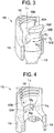
- FIGS. 2-6 illustrate an exemplary embodiment of a bone anchor assembly 110 that includes a compression cap 160 configured to mate to and engage a receiver member 114 such that the compression cap 160 is retained within the receiver member 114.
- the compression cap 160 is configured to be seated within a recess 130 of the receiver member 114, proximally of the bone anchor 112, and the compression cap 160 can include features formed thereon that engage corresponding engagement features formed on the receiver member 114.
- the compression cap 160 can apply a frictional force to the bone anchor 112 to substantially maintain the anchor 112 at a desired angle with respect to the receiver member 114, while still allowing the angular orientation of the anchor 112 to be adjusted. Engagement of the corresponding engagement features can be sufficient to prevent removal of the compression cap 160 from the receiver member 114, and optionally to substantially prevent longitudinal and/or rotational movement of the compression cap 160 with respect to the receiver member 114 when no force is applied thereto.
- Engagement features of the compression cap 160 for engaging the receiver member 114 can be formed anywhere on a surface of the compression cap 160 that is configured to contact the receiver member 114.
- the engagement features are in the form of wings 161A, 161B that project radially outward from outward-facing surfaces of the opposed arms 162A, 162B, distally of flanges 165A, 165B on the arms 162A, 162B.
- the wings 161A, 161B can extend around an entire width of each of the arms 162A, 162B measured along a circumference of the compression cap 160, although it will be appreciated that the width W C of the wings 161A, 161B can be smaller than the width of the arms 162A, 162B, and can be either the same or different from one another. Moreover, it will be appreciated that although the illustrated wings 161A, 161B extend in a plane that is substantially perpendicular to the longitudinal axis L 1 of the compression cap 160, the wings 161 A, 161B can extend in any plane, either the same or different from one another.
- the longitudinal position of the wings 161 A, 161B along the longitudinal length of the compression cap 160 can vary, but preferably the wings 161A, 161B are formed at a location that corresponds to a location of complementary engagement features in the receiver member 114, discussed below, and at a location that will retain the compression cap 1 60 within the receiver member 114 at a predetermined position just proximal to the head of the bone anchor 112, and more preferably at a predetermined position effective to apply some amount of frictional force to the head of the bone anchor 112. As shown in FIG.
- the wings 161A, 161B are located distal to the flanges 165A, 165B and proximal to the distal end 166 and also just proximal to the distal-most end of the U-shaped cut-out 164 formed in the compression cap 160.
- the wings 161A, 161B can have any shape and dimension, either the same or different from one another.
- the wings 161A, 161B are in the form of elongate protrusions or ridges formed on the outer surface of each arm 162A, 162B.
- the wings 161A, 161B have a width W C measured horizontally about a circumference of the compression cap 160, a height H C measured along a longitudinal axis L 1 of the compression cap 160, and a depth or thickness T C measured along a radial axis of the compression cap 160.
- the width W C of the wings 161A, 161B can vary depending on the total width of the arms 162A, 162B, and the width W C can be equal to or less than a total width of the arms 162A, 162B.
- the height H C and thickness T C of the wings 161A, 161B can also vary, but preferably the height H C and thickness T C are small enough to allow for insertion of the compression cap 160 into the recess 130 of the receiver member 114.
- the wings 161A, 161B have a height. H C and thickness T C that are small enough to allow the wings 161A, 1 61B to deflect as the compression cap 160 is inserted into the receiver member 114, as described in more detail below.
- the engagement features of the illustrated embodiment are in the form of wings 161A, 161B, it will be appreciated by a person skilled in the art that the compression cap 160 can have a variety of engagement features thereon for engaging the receiver member 114. Moreover, although there are only two wings 161 A, 161B in the illustrated embodiment, it will be appreciated by a person skilled in the art that the compression cap 160 can have any number of engagement features formed thereon.
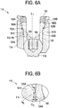
- the receiver member 114 includes pockets 124A, 124B formed on inner walls of the opposed arms 128A, 128B.
- the pockets 124A, 124B are configured to seat the wings 161A, 161B of the compression cap 160 when the compression cap 160 is in a secured configuration.
- the location of the pockets 124A, 124B within the receiver member 114 can vary, but as indicated above with respect to the compression cap 160, the pockets 124A, 124B are preferably at a location that seats the compression cap 160 in a predetermined position that is proximal of the head of the bone anchor 112, The location can also be configured to position the u-shaped cut-outs formed between the arms 162A, 162B of the compression cap 160 in alignment with u-shaped cut-outs formed between the arms 128A, 128B of the receiver member 114.
- the pockets 124A, 124B are located distal of the threads 142 formed in a proximal portion of the receiver member 114, and proximal of the distal-most end of the u-shaped cut-outs formed between the arms 128A, 128B.
- the pockets 124A, 124B can have any shape and dimension, either the same or different from one another, but they preferably have a shape and size that allows the wings 161A, 161B to be seated and retained therein. At least one dimension of the pockets 124A, 124B can be substantially the same as or slightly smaller than a corresponding dimension of the wings 161A, 161B to provide for an interference fit between the wings 161A, 161B and the pockets 124A, 124B, and/or at least one dimension of the pockets 124A, 124B can be slightly larger than a corresponding dimension of the wings 161 A, 161B to allow for some adjustment of the compression cap 160 within the recess 130 when the compression cap 160 is in the secured configuration.
- the pockets 124A, 124B have a width W R measured horizontally about a circumference of the receiver member 114 that is substantially the same as the width W C of the wings 161A, 161B, a depth D R measured along a radial axis of the receiver member 114 that is substantially the same as the thickness T C of the wings 161A, 161 B, and a height L R measured along the longitudinal axis L 1 of the compression cap 160 that is substantially the same as a height H C of the wings 161A, 161B.
- a total diameter between an outer-most surface of each of the wings 161 A, 161B can also be greater than an inner diameter of the receiver member 114 so as to prevent removal of the compression cap 160 once mated with the receiver member 114.
- a tight fit between at least two of the corresponding dimensions, e.g., between the width W C of the compression cap 160 and the width W R of the receiver member 114, and/or between the height H C of the compression cap 160 and the height H R of the receiver member 114, and/or between the thickness T C of the compression cap 160 and the depth D R of the receiver member 114, can help to substantially prevent both longitudinal and rotational movement of the compression cap 160 once the compression cap 160 is in the secured configuration.
- a small difference between the height H C of the wings 161 A, 161B and the height H R of the pockets 124A, 124B can allow for proximal-distal movement of the compression cap 160, thus allowing for further tightening of the compression cap 160 against the bone anchor 112.
- This can be achieved by applying a closure member (not shown) to the receiver member 114 so as to cause a spinal fixation rod seated within the receiver member 114 to apply a distal force to the compression cap 160 to thereby cause the compression cap 160 to frictionally engage and lock the bone anchor 112 in a fixed position relative to the receiver member 114.
- the additional space within the pockets 124A, 124B along the longitudinal axis L 1 of the compression cap 160 can allow for the bone anchor 112 to assume various angles with respect to the longitudinal axis L 1 of the compression cap 160 prior to locking the bone anchor assembly.
- the relative heights H C , H R are configured so as to cause the compression cap 160 to apply friction to the bone anchor 112 to maintain the bone anchor 112 at a desired angle when no closure mechanism is applied to the receiver member 114. The friction can be overcome by applying a force to the receiver member 114 to adjust the angle as desired.
- the corresponding engagement features of the compression cap 160 and the receiver member 114 can be configured to facilitate insertion of the compression cap 160 into the receiver member 114, but to inhibit or prevent removal of the compression cap 160 from the receiver member 114.
- a user can apply a distally-directed force to overcome the resistive force of the wings 161A, 161B against the inner walls of the receiver member 114.
- the resistive force can be reduced by complementary lead-in surface geometries of the wings 161A, 161B and the receiver member 114.
- the wings 161A, 161B have ramped distal-facing surfaces that are complementary to ramped shoulders 125A, 125B of the arms 128A, 128B of the receiver member 114, such that the wings 161A, 161B can slide along the shoulders 125A, 125B of the arms 128A, 128B as the compression cap 160 is advanced distally into the recess 130.
- one or all of the wings 161A, 161B, the cap's arms 162A, 162B, and the receiver's arms 128A, 128B can be formed from one or more flexible materials.
- the wings 161A, 161B can be formed from one or more flexible materials that can allow the wings 161A, 161B to deflect or bend proximally as the wings 161A, 161B pass through the receiver member 114 and into the pockets 124A, 124B.
- the wings 161A, 161B can be formed from a shape memory material that can allow the wings 161A, 161B to compress or deform inwardly as the wings 161A, 161B pass through the receiver member 114 and then expand once the wings 161A, 161B are seated within the pockets 124A, 124B.
- the wings 161A, 161B can be biased inwardly, e.g., by springs, and can deflect outwardly as the compression cap 160 is advanced through the receiver member 114 and then return to the biased inward position once the wrings 161A, 161B are aligned with the pockets 124A, 124B.
- the wings 161A, 161B can snap into engagement with the pockets 124A, 124B, thus providing tactile feedback to a user and helping to inhibit or prevent subsequent removal of the compression cap 160 from the receiver member 114.
- the arms 162A, 162B of the compression cap 160 can deflect inwardly as the compression cap 160 is inserted into the recess 130, and/or the arms 128A, 128B of the receiver member 114 can deflect outwardly as the compression cap 160 is inserted into the recess 130.
- the wings 161A, 161B can have proximal-facing surfaces that extend in a plane substantially perpendicular to the longitudinal axis L 1 of the compression cap 160. Once the wings 161A, 161B are seated within the pockets 124A, 124B in the secured configuration, the proximal-facing surfaces of the wings 161A, 161B can abut distal-facing surfaces of the pockets 124A, 124B, which can also extend in a plane substantially perpendicular to the longitudinal axis L 1 of the compression cap 160.
- the wings 161A, 161 B can be configured such that distal or outward flexion of the wings 161A, 161B away from the compression cap 160 is more difficult to achieve than any proximal or inward flexion of the wings 161A, 161 B toward the compression cap 160 that is required for insertion of the wings 161A, 161B into the pockets 124A, 124B, e.g., the wings 161A, 161B can be biased proximally.
- a distal-facing surface 166 of the compression cap 160 can exert a frictional force on a proximal head 118 of the bone anchor 112 to substantially maintain the head 118 in a fixed position relative to the receiver member 114.
- the force should be sufficient to prevent free movement of the bone anchor 112 relative to the receiver member 114 while still allowing a user to move the receiver member 114 relative to the bone anchor 112.
- the force can vary slightly when the compression cap 160 is in the secured configuration, as the compression cap 160 can be capable of some longitudinal movement.
- the pockets 124A, 124B can have a slightly greater height H R than a corresponding height H C of the wings 161A, 161B, thereby allowing for slight movement of the wings 161A, 161B and thus the compression cap 160 along a longitudinal axis L 1 of the compression cap 160. This can be necessary to allow for minor adjustments to the angle of the bone anchor 112 and for further tightening of the compression cap 160 against the proximal head 118. As shown in FIGS.
- the proximal head 118 of the bone anchor 112 can be substantially spherical to match a corresponding spherical distal surface 166 of the compression cap 160, thus allowing for articulation of the bone anchor 112 at an angle to the longitudinal axis L 1 of the cap 160.
- the compression cap 160 is distally advanced and in a locked configuration, e.g., by applying a closure mechanism (not shown) to the receiver member 114, the spherical distal surface 166 of the compression cap 160 can engage the proximal head 118 of the bone anchor 112 to thereby lock the bone anchor at a fixed position relative to the receiver member 114.
- distal spherical surface 166 of the compression cap 160 and the proximal head 118 of the bone anchor 112 can each include opposed flats formed thereon and configured to limit angular movement of the bone anchor 112 to a single plane of motion, e.g., to thereby provide uniplanar motion.
- the corresponding engagement features of a compression member and a receiver member can be of any shape and size, and can be configured to engage each other in a variety of ways.
- a bone anchor assembly 210 having corresponding engagement features formed on a compression member and a receiver member is illustrated in FIGS. 7-11 .
- the bone anchor assembly 210, as well as other bone anchor assemblies described herein, can generally be configured and used similar to the bone anchor assembly 110 of FIGS. 2-6 .
- like-named elements and like-illustrated elements of the bone anchor assembly 110 and of the other bone anchor assemblies discussed herein can be configured and used similar to one another.
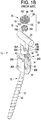
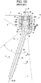
- FIGS. 7-11 illustrate the bone anchor assembly 210 having a compression cap 260 configured to secure a bone anchor 212 at a fixed angle to a receiver member 214.
- Corresponding engagement features formed on the compression cap 260 and the receiver member 214 can be configured to engage one another upon rotation of the compression cap 260 with respect to the receiver member 214.
- rotation of the compression cap 260 can move the compression cap 260 from an unsecured configuration, shown in FIG. 7 , where the corresponding engagement features are unengaged, to a secured configuration, shown in FIG. 8 , where the corresponding engagement features are engaged.
- a user can distally advance the compression cap 260 into a recess 230 of the receiver member 214 such that opposed arms 262A, 262B of the compression cap 260 are offset from opposed arms 228A, 228B of the receiver member 214, and then rotate the compression cap 260 while applying a distal force to cause the opposed arms 262A, 262B of the compression cap 260 to be aligned with the opposed arms 228A, 228B.
- the angle of rotation required to move the compression cap 260 between the unsecured and the secured configurations is approximately 90 degrees, although the angle of rotation can vary from about 10 to 90 degrees depending on various factors, e.g., the dimensions of the opposed arms 262A, 272B of the compression cap 260 relative to the opposed arms 228A, 228B of the receiver member 214, the dimensions and location of the corresponding engagement features, etc.
- Engagement features of the compression cap 260 can be a variety of shapes and sizes, although in the illustrated embodiment the engagement features are in the form of wings 261A, 261B extending radially from the opposed arms 262A, 262B of the compression cap 260 and configured to engage complementary engagement features of the receiver member 214.
- both proximal and distal-facing surfaces of the wings 261A, 261B on the compression cap 260 are upwardly sloped at substantially the same angle to a longitudinal axis L 2 of the compression cap 260, such that radially outermost edges of the wings 261A, 261B are proximal of radially innermost edges of the wings 261A, 261B.
- the sloped surfaces of the wings 261A, 261B can thus allow distal advancement of the compression cap 260 into the receiver member, while substantially preventing proximal movement of the compression cap 260 and reducing a likelihood of loss or removal of the compression cap 260 once it is in the secured configuration.
- the compression cap 260 can be adjusted longitudinally while in the secured configuration, however, to allow for additional tightening of the compression cap 260 against the bone anchor 212 and/or for articulation of the bone anchor 212 to a desired angle, as discussed above.
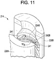
- shelves 242A, 242B extend radially inward from inner walls of the arms 228A, 228B of the receiver member 214 and are configured to engage the wings 261A, 261B of the compression cap 260.
- the shelves 242A, 242B can be disposed anywhere along the inner walls of the arms 228A, 228B, although in the illustrated embodiment the shelves 242A, 242B are disposed distally of threads 242 that can be configured to engage a closure mechanism, e.g., a set screw. As shown in FIG.
- cut-outs 224A, 224B formed on distal-facing sides of the shelves 242A, 242B can be provided for receiving the wings 261A, 261B when the compression cap 260 is in the secured configuration, although it will be appreciated by a person skilled in the art that the shelves 242A, 242B do not require any modifications to engage the wings 261A, 261B. In another embodiment (not shown), any one or more of the threads 242 can be configured to engage the wings 261A, 261B.
- the cut-outs 224A, 224B of the receiver member 214 can be configured to facilitate transition of the compression cap 260 into the secured configuration, but to inhibit or prevent transition of the compression cap 260 out of the secured configuration. In the illustrated embodiment, shown in FIG.
- the cut-outs 224A, 224B can have substantially the same dimensions as the wings 261A, 261B, although the cut-outs 224A, 224B can have at least one dimension that is slightly smaller than a corresponding dimension of the wings 261A, 261B to create an interference fit between the wings 261A, 261B and the cut-outs 224A, 224B and/or to allow for a snapping effect as the wings 261A, 261B are inserted into the cut-outs 224A, 224B.
- a width W C of the wings 261A, 261B measured around a circumference of the compression cap 260 can be slightly larger than a width W R of the cut-outs 224A, 224B measured around a circumference of the receiver member 214, bounded on either end by ramped edges 241.
- the ramped edges 241 can have a slope inclined upwards towards a center of each of the cut-outs 224A, 224B, and planar side surfaces that abut opposite ends of the wings 261A, 261 B when the compression cap 260 is in the secured position.
- the ramped edges 241 can thus provide a lead-in surface geometry as the wings 261A, 261B are rotated into the secured configuration and/or can inhibit removal of the compression cap 260 from the receiver member 214 by rotation once the compression cap 260 is in the secured configuration.
- the wings 261A, 261B can be formed from a flexible material that is capable of being distally deflected as a user rotates the compression cap 260 from the unsecured to the secured configuration, such that the wings 261A, 261B are slightly bent by the ramped edges 241 as the compression cap 260 is rotated into the secured configuration and/or such that the wings 261A, 261B snap into alignment with the cut-outs 224A, 224B.
- the wings 261A, 261B remain distally deflected while in the secured configuration, thus further securing the compression cap 260 to the receiver member 214 and providing additional distal force against the bone anchor 212.
- bone anchor assemblies include male engagement features on a compression cap and female engagement features on a corresponding receiver member
- the engagement features can be reversed with the compression cap having female engagement features and the receiver member having corresponding male engagement features.
- the receiver member can have wings extending from inner walls thereof that can be configured to engage recesses formed on outer surfaces of the compression cap. The wings and corresponding recesses can be configured and used similarly to those described above for bone anchor assemblies 110, 210.
- a bone anchor assembly can be assembled, either during manufacturing or intraoperatively, by passing an elongate shank of a bone anchor in a proximal-to-distal direction through an aperture formed in a distal end of a receiver member.
- a proximal head portion of the bone anchor can be polyaxially seated in a spherical recess formed in a distal portion of the receiver member.
- a compression member can be inserted between the opposed arms of the receiver member, proximal to the proximal head of the bone anchor.
- Corresponding engagement features of the compression member and the receiver member can be engaged by urging the compression member distally within the receiver member, or, in another aspect, by rotating and distally advancing the compression member into the receiver member.
- Engagement of the corresponding engagement features in a secured configuration can prevent proximal movement of the compression member with respect to the receiver member, thus securing the compression member within the receiver member.
- Such engagement can also cause the compression member to apply a frictional force to the head of the bone anchor to maintain the bone anchor at a fixed angle with respect to the receiver member.
- An angle of the bone anchor with respect to the receiver member can be adjusted by applying a force sufficient to overcome the frictional force.
- the assembled bone anchor can be implanted in a bone of a patient.
- the bone can be prepared to receive the bone anchor assembly, e.g., by drilling an appropriately sized hole.
- a driver tool can be fitted with the bone anchor to drive the bone anchor into the prepared hole in the bone.
- a spinal fixation element e.g., a rod, can be located in between the arms of the receiver member.
- a closure mechanism can be engaged with an inner thread formed on opposed arms of the receiver member, proximally of the rod, which can urge the compression member further distally to exert a frictional force on the head of the bone anchor and thus lock the bone anchor at a fixed angle with respect to the receiver member.
Landscapes
- Health & Medical Sciences (AREA)
- Orthopedic Medicine & Surgery (AREA)
- Life Sciences & Earth Sciences (AREA)
- Neurology (AREA)
- Surgery (AREA)
- Heart & Thoracic Surgery (AREA)
- Engineering & Computer Science (AREA)
- Biomedical Technology (AREA)
- Nuclear Medicine, Radiotherapy & Molecular Imaging (AREA)
- Medical Informatics (AREA)
- Molecular Biology (AREA)
- Animal Behavior & Ethology (AREA)
- General Health & Medical Sciences (AREA)
- Public Health (AREA)
- Veterinary Medicine (AREA)
- Surgical Instruments (AREA)
Claims (15)
- Ensemble d'ancrage osseux (110) comprenant :un ancrage osseux (112) ayant une partie de tête proximale (118) et une partie de tige distale ;un élément de réception (114) ayant un siège polyaxial formé à l'intérieur de ce dernier et configuré pour installer de manière polyaxiale la partie de tête de l'ancrage osseux ; etun capuchon de compression (160) disposé à l'intérieur de l'élément de réception et ayant une extrémité distale (166) configurée pour mettre en prise la partie de tête de l'ancrage osseux et une paire de bras espacés (162A, 162B) définissant un siège en forme de U (64) pour recevoir un élément de fixation vertébral (22), le capuchon de compression comprenant des brides (165A, 165B) et des ailes (161A, 161B) opposées s'étendant radialement à partir des surfaces orientées vers l'extérieur des bras du capuchon de compression, les ailes opposées étant distales par rapport aux brides et configurées pour se coupler avec des poches (124A, 124B) formées dans l'élément de réception de sorte que le capuchon de compression est retenu à l'intérieur de l'élément de réception et exerce une force de friction sur la partie de tête de l'ancrage osseux afin d'empêcher le libre déplacement de l'ancrage osseux par rapport à l'élément de réception tout en permettant toujours à un utilisateur de déplacer l'élément de réception par rapport à l'ancrage osseux ;dans lequel l'élément de réception comprend en outre des épaulements à rampe (125A, 125B) disposés à proximité des poches qui sont configurées pour déformer les ailes lorsque le capuchon de compression est avancé de manière distale dans l'élément de réception ;dans lequel les bras du capuchon de compression sont configurés pour dévier vers l'intérieur lorsque le capuchon de compression est inséré dans l'élément de réception.
- Ensemble d'ancrage osseux (110) selon la revendication 1, dans lequel les ailes (161A, 161B) opposées et les poches (124A, 124B) sont effectives, lorsqu'elles sont couplées, pour maintenir le capuchon de compression (160) dans une position longitudinale sensiblement fixe par rapport à l'élément de réception (114) .
- Ensemble d'ancrage osseux (110) selon la revendication 1, dans lequel les ailes (161A, 161B) opposées sont configurées pour s'encliqueter en mise en prise avec les poches (124A, 124B) lorsque le capuchon de compression (160) est déplacé de manière distale à l'intérieur de l'élément de réception (114) au-dessous des épaulements à rampe (125A, 125B).
- Ensemble d'ancrage osseux (110) selon la revendication 1, dans lequel un diamètre externe du capuchon de compression (160) est inférieur à un diamètre interne de l'élément de réception (114).
- Ensemble d'ancrage osseux (110) selon la revendication 1, dans lequel une distance entre les surfaces externes des ailes (161A, 161B) opposées est supérieure au diamètre interne de l'élément de réception (114).
- Ensemble d'ancrage osseux (110) selon la revendication 1, dans lequel une surface orientée de manière distale de chaque aile (161A, 161B) présente une rampe pour fournir une géométrie de surface d'attaque.
- Ensemble d'ancrage osseux (110) selon la revendication 1, dans lequel une surface orientée de manière proximale de chaque aile (161A, 161B) et une surface supérieure interne de chaque poche (124A, 124B) sont planaires de sorte que, lorsqu'elles sont couplées, le capuchon de compression (160) ne peut pas être découplé de l'élément de réception (114).
- Ensemble d'ancrage osseux (110) selon la revendication 1, dans lequel les ailes (161A, 161B) opposées et les poches (124A, 124B) sont effectives, lorsqu'elles sont couplées, pour maintenir le capuchon de compression (160) dans une position de rotation sensiblement fixe par rapport à l'élément de réception (114).
- Ensemble d'ancrage osseux (110) selon la revendication 1, dans lequel la rotation du capuchon de compression (160) par rapport à l'élément de réception (114) est effective pour déplacer les ailes (161A, 161B) opposées en mise en prise avec les poches (124A, 124B).
- Ensemble d'ancrage osseux (110) selon la revendication 1, dans lequel la rotation du capuchon de compression (160) par rapport à l'élément de réception (114) est effective pour déformer les ailes (161A, 161B) opposées jusqu'à ce que les ailes opposées s'encliquettent en mise en prise avec les poches (124A, 124B).
- Ensemble d'ancrage osseux (110) selon la revendication 1, dans lequel les poches (124A, 124B) comprennent des découpes formées dans une étagère qui s'étend radialement vers l'intérieur à partir d'une paroi latérale intérieure de l'élément de réception (114).
- Ensemble d'ancrage osseux (110) selon la revendication 11, dans lequel l'étagère comprend un ou plusieurs bords latéraux qui présentent une rampe afin de fournir une surface d'attaque pour les ailes (161A, 161B) opposées.
- Ensemble d'ancrage osseux (110) selon la revendication 1, dans lequel une largeur de chaque aile (161A, 161B) mesurée horizontalement autour de la circonférence du capuchon de compression (160) est supérieure à une épaisseur de l'aile opposée mesurée le long d'un axe radial du capuchon de compression.
- Ensemble d'ancrage osseux (110) selon la revendication 1, dans lequel au moins une dimension des poches (124A, 124B) est légèrement plus grande qu'une dimension correspondante des ailes (161A, 161B) pour permettre un certain ajustement du capuchon de compression (160) lorsque les ailes (161A, 161B) sont installées dans les poches (124A, 124B).
- Ensemble d'ancrage osseux (110) selon la revendication 1, dans lequel les poches (124A, 124B) formées dans l'élément de réception (114) ont une profondeur (DR) mesurée le long d'un axe radial de l'élément de réception qui est sensiblement la même qu'une épaisseur (TC) des ailes (161A, 161B) opposées.
Priority Applications (1)
| Application Number | Priority Date | Filing Date | Title |
|---|---|---|---|
| EP19211131.8A EP3632357B1 (fr) | 2013-03-14 | 2014-03-06 | Éléments de compression de verrouillage pour utilisation avec des ensembles d'ancrage osseux |
Applications Claiming Priority (2)
| Application Number | Priority Date | Filing Date | Title |
|---|---|---|---|
| US13/827,092 US9259247B2 (en) | 2013-03-14 | 2013-03-14 | Locking compression members for use with bone anchor assemblies and methods |
| PCT/US2014/021198 WO2014158972A1 (fr) | 2013-03-14 | 2014-03-06 | Éléments de compression de verrouillage pour utilisation avec des ensembles d'ancrage osseux et procédés |
Related Child Applications (1)
| Application Number | Title | Priority Date | Filing Date |
|---|---|---|---|
| EP19211131.8A Division EP3632357B1 (fr) | 2013-03-14 | 2014-03-06 | Éléments de compression de verrouillage pour utilisation avec des ensembles d'ancrage osseux |
Publications (2)
| Publication Number | Publication Date |
|---|---|
| EP2956074A1 EP2956074A1 (fr) | 2015-12-23 |
| EP2956074B1 true EP2956074B1 (fr) | 2019-11-27 |
Family
ID=50397283
Family Applications (2)
| Application Number | Title | Priority Date | Filing Date |
|---|---|---|---|
| EP14714480.2A Active EP2956074B1 (fr) | 2013-03-14 | 2014-03-06 | Éléments de compression de verrouillage pour utilisation avec des ensembles d'ancrage osseux |
| EP19211131.8A Active EP3632357B1 (fr) | 2013-03-14 | 2014-03-06 | Éléments de compression de verrouillage pour utilisation avec des ensembles d'ancrage osseux |
Family Applications After (1)
| Application Number | Title | Priority Date | Filing Date |
|---|---|---|---|
| EP19211131.8A Active EP3632357B1 (fr) | 2013-03-14 | 2014-03-06 | Éléments de compression de verrouillage pour utilisation avec des ensembles d'ancrage osseux |
Country Status (3)
| Country | Link |
|---|---|
| US (5) | US9259247B2 (fr) |
| EP (2) | EP2956074B1 (fr) |
| WO (1) | WO2014158972A1 (fr) |
Families Citing this family (37)
| Publication number | Priority date | Publication date | Assignee | Title |
|---|---|---|---|---|
| US9980753B2 (en) * | 2009-06-15 | 2018-05-29 | Roger P Jackson | pivotal anchor with snap-in-place insert having rotation blocking extensions |
| US8444681B2 (en) | 2009-06-15 | 2013-05-21 | Roger P. Jackson | Polyaxial bone anchor with pop-on shank, friction fit retainer and winged insert |
| US8007522B2 (en) | 2008-02-04 | 2011-08-30 | Depuy Spine, Inc. | Methods for correction of spinal deformities |
| CA2739997C (fr) * | 2008-08-01 | 2013-08-13 | Roger P. Jackson | Element longitudinal de liaison avec cordons tendus gaines |
| US11229457B2 (en) | 2009-06-15 | 2022-01-25 | Roger P. Jackson | Pivotal bone anchor assembly with insert tool deployment |
| US12383311B2 (en) | 2010-05-14 | 2025-08-12 | Roger P. Jackson | Pivotal bone anchor assembly and method for use thereof |
| US9113960B2 (en) * | 2010-06-08 | 2015-08-25 | Globus Medical, Inc. | Conforming bone stabilization receiver |
| WO2012128825A1 (fr) * | 2011-03-24 | 2012-09-27 | Jackson Roger P | Ancrage osseux polyaxial avec articulation composée et tige enclipsable |
| US9993269B2 (en) * | 2011-07-15 | 2018-06-12 | Globus Medical, Inc. | Orthopedic fixation devices and methods of installation thereof |
| EP2606841B1 (fr) * | 2011-12-23 | 2016-03-09 | Biedermann Technologies GmbH & Co. KG | Dispositif polyaxial d'ancrage osseux |
| US8911479B2 (en) | 2012-01-10 | 2014-12-16 | Roger P. Jackson | Multi-start closures for open implants |
| US9782204B2 (en) | 2012-09-28 | 2017-10-10 | Medos International Sarl | Bone anchor assemblies |
| US10058354B2 (en) | 2013-01-28 | 2018-08-28 | Roger P. Jackson | Pivotal bone anchor assembly with frictional shank head seating surfaces |
| EP2764840B1 (fr) | 2013-02-11 | 2017-05-03 | Biedermann Technologies GmbH & Co. KG | Ensemble de couplage d'une tige à un élément d'ancrage osseux et dispositif d'ancrage osseux avec un tel ensemble de couplage |
| US9775660B2 (en) | 2013-03-14 | 2017-10-03 | DePuy Synthes Products, Inc. | Bottom-loading bone anchor assemblies and methods |
| US9724145B2 (en) | 2013-03-14 | 2017-08-08 | Medos International Sarl | Bone anchor assemblies with multiple component bottom loading bone anchors |
| US9259247B2 (en) | 2013-03-14 | 2016-02-16 | Medos International Sarl | Locking compression members for use with bone anchor assemblies and methods |
| US10342582B2 (en) | 2013-03-14 | 2019-07-09 | DePuy Synthes Products, Inc. | Bone anchor assemblies and methods with improved locking |
| US20140277153A1 (en) | 2013-03-14 | 2014-09-18 | DePuy Synthes Products, LLC | Bone Anchor Assemblies and Methods With Improved Locking |
| US10064658B2 (en) | 2014-06-04 | 2018-09-04 | Roger P. Jackson | Polyaxial bone anchor with insert guides |
| US11219471B2 (en) | 2014-10-21 | 2022-01-11 | Roger P. Jackson | Pivotal bone anchor receiver having an insert with post-placement tool deployment |
| US10543021B2 (en) * | 2014-10-21 | 2020-01-28 | Roger P. Jackson | Pivotal bone anchor assembly having an open ring positioner for a retainer |
| EP3031415B1 (fr) * | 2014-12-10 | 2018-10-31 | Biedermann Technologies GmbH & Co. KG | Ensemble d'accouplement et dispositif d'ancrage osseux polyaxial comprenant celui-ci |
| JP6533400B2 (ja) * | 2015-03-20 | 2019-06-19 | 株式会社 田中医科器械製作所 | 脊椎固定用インプラント |
| US9833263B2 (en) | 2015-04-13 | 2017-12-05 | Medos International Sarl | Bone anchor assemblies with orientation indicator |
| DE102015109481A1 (de) * | 2015-06-15 | 2016-12-15 | Aesculap Ag | Pedikelschraube mit radial versetzter Führung |
| US10568667B2 (en) * | 2016-07-13 | 2020-02-25 | Medos International Sàrl | Bone anchor assemblies and related instrumentation |
| US10874438B2 (en) | 2016-07-13 | 2020-12-29 | Medos International Sarl | Bone anchor assemblies and related instrumentation |
| WO2018186887A1 (fr) * | 2017-04-07 | 2018-10-11 | Facet-Link Inc. | Élément de fixation vertébrale et système de stabilisation |
| US10610265B1 (en) | 2017-07-31 | 2020-04-07 | K2M, Inc. | Polyaxial bone screw with increased angulation |
| WO2020056385A1 (fr) | 2018-09-13 | 2020-03-19 | Jackson Roger P | Ensemble d'ancrage osseux pivotant à récepteur modulaire et tête de tige universelle |
| US11234738B2 (en) | 2018-11-16 | 2022-02-01 | Roger P. Jackson | Pivotal bone anchor assembly having a deployable collet insert with internal pressure ring |
| US11571244B2 (en) | 2019-05-22 | 2023-02-07 | Nuvasive, Inc. | Posterior spinal fixation screws |
| WO2021127251A1 (fr) | 2019-12-17 | 2021-06-24 | Jackson Roger P | Ensemble ancrage osseux avec dispositif de retenue d'anneau fermé et bague d'encliquetage interne |
| US11191573B1 (en) * | 2021-02-16 | 2021-12-07 | Globus Medical Inc. | Orthopedic fixation devices and methods thereof |
| WO2022184797A1 (fr) | 2021-03-05 | 2022-09-09 | Medos International Sarl | Vis polyaxiale à verrouillage sélectif |
| US11751915B2 (en) | 2021-07-09 | 2023-09-12 | Roger P. Jackson | Modular spinal fixation system with bottom-loaded universal shank heads |
Citations (1)
| Publication number | Priority date | Publication date | Assignee | Title |
|---|---|---|---|---|
| EP2286748A1 (fr) * | 2009-08-20 | 2011-02-23 | BIEDERMANN MOTECH GmbH | Dispositif d'ancrage d'os, outil et procédé d'assemblage de celui-ci et outil destiné à être utilisé avec celui-ci. |
Family Cites Families (421)
| Publication number | Priority date | Publication date | Assignee | Title |
|---|---|---|---|---|
| BE469107A (fr) | 1945-01-25 | |||
| US2842180A (en) | 1950-02-23 | 1958-07-08 | Set Screw & Mfg Company | Self-locking threads with locking interference fit |
| US2788045A (en) | 1952-10-06 | 1957-04-09 | Rosan Joseph | Conventional truncated screw threads with small locking thread bonded therebetween |
| US4124318A (en) | 1978-03-23 | 1978-11-07 | General Motors Corporation | Splined assembly with retaining rings |
| US4762024A (en) | 1985-07-30 | 1988-08-09 | Dana Corporation | Shaft retaining means for a differential gear assembly |
| US5009017A (en) | 1987-01-20 | 1991-04-23 | Caterpillar Inc. | Retaining pin having a positive keeper means |
| FR2642643B1 (fr) | 1989-02-09 | 1991-05-10 | Vignaud Jean Louis | Instrumentation rachidienne pour fixation pediculaire universelle par vis diapason a reglage micrometrique |
| FR2658414B1 (fr) | 1990-02-19 | 1992-07-31 | Sofamor | Implant pour dispositif d'osteosynthese en particulier du rachis. |
| WO1991016020A1 (fr) | 1990-04-26 | 1991-10-31 | Danninger Medical Technology, Inc. | Systeme de vis transpediculaire et procede d'utilisation de celle-ci |
| US5102412A (en) | 1990-06-19 | 1992-04-07 | Chaim Rogozinski | System for instrumentation of the spine in the treatment of spinal deformities |
| NL9001778A (nl) | 1990-08-07 | 1992-03-02 | Stichting Tech Wetenschapp | Scoliose-correctie. |
| DE9202745U1 (de) | 1992-03-02 | 1992-04-30 | Howmedica Gmbh, 2314 Schoenkirchen | Vorrichtung zum Verspannen von Wirbeln der menschlichen Wirbelsäule |
| DE59301618D1 (de) | 1992-06-04 | 1996-03-28 | Synthes Ag | Osteosynthetisches Befestigungselement |
| WO1994000066A1 (fr) | 1992-06-25 | 1994-01-06 | Synthes Ag Chur | Dispositif de contention osteosynthetique |
| US5281223A (en) | 1992-09-21 | 1994-01-25 | Ray R Charles | Tool and method for derotating scoliotic spine |
| US5306275A (en) | 1992-12-31 | 1994-04-26 | Bryan Donald W | Lumbar spine fixation apparatus and method |
| FR2702362B3 (fr) | 1993-02-24 | 1995-04-14 | Soprane Sa | Fixateur pour les ostéosynthèses du rachis lombo-sacré. |
| DE4307576C1 (de) | 1993-03-10 | 1994-04-21 | Biedermann Motech Gmbh | Knochenschraube |
| US5487744A (en) | 1993-04-08 | 1996-01-30 | Advanced Spine Fixation Systems, Inc. | Closed connector for spinal fixation systems |
| US6077262A (en) | 1993-06-04 | 2000-06-20 | Synthes (U.S.A.) | Posterior spinal implant |
| DE9402839U1 (de) * | 1994-02-22 | 1994-04-14 | Howmedica GmbH, 24232 Schönkirchen | Vorrichtung zum Einrichten einer Wirbelsäule mit geschädigten Wirbeln |
| US5580246A (en) | 1995-01-30 | 1996-12-03 | Fried; Paula S. | Dental implants and methods for extending service life |
| US5643260A (en) | 1995-02-14 | 1997-07-01 | Smith & Nephew, Inc. | Orthopedic fixation system |
| DE19509332C1 (de) | 1995-03-15 | 1996-08-14 | Harms Juergen | Verankerungselement |
| US5562661A (en) | 1995-03-16 | 1996-10-08 | Alphatec Manufacturing Incorporated | Top tightening bone fixation apparatus |
| FR2750595B1 (fr) | 1996-07-02 | 1998-12-04 | Dev Sed Soc Et | Vis medicale notamment pour la chirurgie et ancillaire de pose |
| US5797911A (en) | 1996-09-24 | 1998-08-25 | Sdgi Holdings, Inc. | Multi-axial bone screw assembly |
| US5885286A (en) | 1996-09-24 | 1999-03-23 | Sdgi Holdings, Inc. | Multi-axial bone screw assembly |
| US5879350A (en) | 1996-09-24 | 1999-03-09 | Sdgi Holdings, Inc. | Multi-axial bone screw assembly |
| CA2264672C (fr) | 1996-10-24 | 2010-11-30 | Spinal Concepts, Inc. | Procede et appareil de fixation vertebrale |
| US6485494B1 (en) | 1996-12-20 | 2002-11-26 | Thomas T. Haider | Pedicle screw system for osteosynthesis |
| US6224596B1 (en) | 1997-01-06 | 2001-05-01 | Roger P. Jackson | Set screw for use with osteosynthesis apparatus |
| AU725487B2 (en) | 1997-01-22 | 2000-10-12 | Synthes Gmbh | Device for connecting a longitudinal bar to a pedicle screw |
| FR2759282B1 (fr) | 1997-02-10 | 1999-05-07 | Eos Medical | Dispositif de vis secable pour plaque d'osteosynthese ou pour la coaptation de deux fragments d'os |
| BR9809079A (pt) | 1997-04-09 | 2002-01-15 | Implant Innovations Inc | Sistema de entrega de implante |
| ATE276709T1 (de) | 1997-05-24 | 2004-10-15 | Straumann Holding Ag | Support zum halten und/oder bilden eines zahnersatzes |
| DE29710484U1 (de) | 1997-06-16 | 1998-10-15 | Howmedica GmbH, 24232 Schönkirchen | Aufnahmeteil für ein Haltebauteil eines Wirbelsäulenimplantats |
| EP0933065A1 (fr) | 1998-02-02 | 1999-08-04 | Sulzer Orthopädie AG | Système de fixation articulé pour une vis à os |
| US6068632A (en) | 1998-05-12 | 2000-05-30 | Carchidi; Joseph Edward | Bone tap apparatus |
| US6113601A (en) | 1998-06-12 | 2000-09-05 | Bones Consulting, Llc | Polyaxial pedicle screw having a loosely coupled locking cap |
| US6565565B1 (en) * | 1998-06-17 | 2003-05-20 | Howmedica Osteonics Corp. | Device for securing spinal rods |
| US6090111A (en) | 1998-06-17 | 2000-07-18 | Surgical Dynamics, Inc. | Device for securing spinal rods |
| US6056753A (en) | 1998-07-13 | 2000-05-02 | Jackson; Roger P. | Set screw for use with osteosynthesis apparatus |
| US6355038B1 (en) | 1998-09-25 | 2002-03-12 | Perumala Corporation | Multi-axis internal spinal fixation |
| US6296642B1 (en) | 1998-11-09 | 2001-10-02 | Sdgi Holdings, Inc. | Reverse angle thread for preventing splaying in medical devices |
| US6050997A (en) | 1999-01-25 | 2000-04-18 | Mullane; Thomas S. | Spinal fixation system |
| DE29903342U1 (de) | 1999-02-24 | 1999-06-02 | Grzibek, Egbert, 97534 Waigolshausen | Fixierelement für Halteelemente von Wirbelsäulenimplantaten |
| US6402757B1 (en) | 1999-03-12 | 2002-06-11 | Biomet, Inc. | Cannulated fastener system for repair of bone fracture |
| US6302888B1 (en) | 1999-03-19 | 2001-10-16 | Interpore Cross International | Locking dovetail and self-limiting set screw assembly for a spinal stabilization member |
| ES2154227B1 (es) | 1999-06-30 | 2001-11-16 | Surgival Co S A | Sistema poliaxial de fijacion de vertebras. |
| FR2796545B1 (fr) | 1999-07-22 | 2002-03-15 | Dimso Sa | Liaison poly-axiale pour systeme d'osteosynthese, notamment pour le rachis |
| US6280442B1 (en) | 1999-09-01 | 2001-08-28 | Sdgi Holdings, Inc. | Multi-axial bone screw assembly |
| CA2423973A1 (fr) | 1999-09-27 | 2001-04-05 | Blackstone Medical, Inc. | Ensemble vis chirurgicale et procedes associes |
| US6629977B1 (en) | 1999-11-15 | 2003-10-07 | Arthrex, Inc. | Tapered bioabsorbable interference screw and method for endosteal fixation of ligaments |
| DE59901090D1 (de) | 1999-12-23 | 2002-05-02 | Storz Karl Gmbh & Co Kg | Schraube mit dezentralem Antrieb |
| US6224598B1 (en) | 2000-02-16 | 2001-05-01 | Roger P. Jackson | Bone screw threaded plug closure with central set screw |
| KR200200582Y1 (ko) | 2000-03-15 | 2000-10-16 | 최길운 | 접골용 보철구 |
| US6251112B1 (en) | 2000-04-18 | 2001-06-26 | Roger P. Jackson | Thin profile closure cap for open ended medical implant |
| US6379356B1 (en) | 2000-04-26 | 2002-04-30 | Roger P. Jackson | Closure for open ended medical implant |
| US6258090B1 (en) | 2000-04-28 | 2001-07-10 | Roger P. Jackson | Closure for open ended medical implant and removal tool |
| US6440132B1 (en) | 2000-05-24 | 2002-08-27 | Roger P. Jackson | Open head bone screw closure with threaded boss |
| US6884244B1 (en) | 2000-06-06 | 2005-04-26 | Roger P. Jackson | Removable medical implant closure for open headed implants |
| US6821277B2 (en) | 2000-06-23 | 2004-11-23 | University Of Southern California Patent And Copyright Administration | Percutaneous vertebral fusion system |
| FR2810874B1 (fr) | 2000-06-30 | 2002-08-23 | Materiel Orthopedique En Abreg | Implant pour dispositif d'osteosynthese comprenant une partie destinee a l'ancrage osseux et un corps de fixation sur une tige |
| US20060083603A1 (en) | 2000-08-23 | 2006-04-20 | Jackson Roger P | Reverse angled threadform with anti-splay clearance |
| US7833250B2 (en) | 2004-11-10 | 2010-11-16 | Jackson Roger P | Polyaxial bone screw with helically wound capture connection |
| US20060025771A1 (en) | 2000-08-23 | 2006-02-02 | Jackson Roger P | Helical reverse angle guide and advancement structure with break-off extensions |
| US6485491B1 (en) | 2000-09-15 | 2002-11-26 | Sdgi Holdings, Inc. | Posterior fixation system |
| US6755829B1 (en) | 2000-09-22 | 2004-06-29 | Depuy Acromed, Inc. | Lock cap anchor assembly for orthopaedic fixation |
| DE10055888C1 (de) | 2000-11-10 | 2002-04-25 | Biedermann Motech Gmbh | Knochenschraube |
| US6454768B1 (en) | 2000-12-05 | 2002-09-24 | Roger P. Jackson | Removable gripping set screw |
| US8377100B2 (en) | 2000-12-08 | 2013-02-19 | Roger P. Jackson | Closure for open-headed medical implant |
| US6726687B2 (en) | 2000-12-08 | 2004-04-27 | Jackson Roger P | Closure plug for open-headed medical implant |
| US6454772B1 (en) | 2000-12-08 | 2002-09-24 | Roger P. Jackson | Set screw for medical implant with gripping side slots |
| US6997927B2 (en) | 2000-12-08 | 2006-02-14 | Jackson Roger P | closure for rod receiving orthopedic implant having a pair of spaced apertures for removal |
| EP1219255B1 (fr) | 2000-12-27 | 2003-10-15 | BIEDERMANN MOTECH GmbH | Vis pour connexion avec une tige |
| US6488681B2 (en) | 2001-01-05 | 2002-12-03 | Stryker Spine S.A. | Pedicle screw assembly |
| US6869433B2 (en) | 2001-01-12 | 2005-03-22 | Depuy Acromed, Inc. | Polyaxial screw with improved locking |
| US6663656B2 (en) | 2001-02-26 | 2003-12-16 | Arthrex, Inc. | Torque driver for interference screw |
| US6764489B2 (en) | 2001-03-27 | 2004-07-20 | Novasive, Inc | Hinged anterior thoracic/lumbar plate |
| DE10115014A1 (de) | 2001-03-27 | 2002-10-24 | Biedermann Motech Gmbh | Verankerungselement |
| US8353932B2 (en) | 2005-09-30 | 2013-01-15 | Jackson Roger P | Polyaxial bone anchor assembly with one-piece closure, pressure insert and plastic elongate member |
| US8292926B2 (en) | 2005-09-30 | 2012-10-23 | Jackson Roger P | Dynamic stabilization connecting member with elastic core and outer sleeve |
| DE10136129A1 (de) | 2001-07-27 | 2003-02-20 | Biedermann Motech Gmbh | Knochenschraube und Befestigungswerkzeug für diese |
| US6974460B2 (en) | 2001-09-14 | 2005-12-13 | Stryker Spine | Biased angulation bone fixation assembly |
| FR2830433B1 (fr) | 2001-10-04 | 2005-07-01 | Stryker Spine | Ensemble pour l'osteosynthese du rachis comprenant une tete d'organe d'ancrage et un outil pour la fixation de la tete |
| US6623485B2 (en) | 2001-10-17 | 2003-09-23 | Hammill Manufacturing Company | Split ring bone screw for a spinal fixation system |
| KR100379194B1 (en) | 2001-10-31 | 2003-04-08 | U & I Co Ltd | Apparatus for fixing bone |
| DE10157814B4 (de) | 2001-11-27 | 2004-12-02 | Biedermann Motech Gmbh | Verschlußeinrichtung zum Sichern eines stabförmigen Elements in einem mit einem Schaft verbundenen Halteelement |
| DE10157969C1 (de) | 2001-11-27 | 2003-02-06 | Biedermann Motech Gmbh | Element mit einem Schaft und einem damit verbundenen Halteelement zum Verbinden mit einem Stab |
| FR2833151B1 (fr) | 2001-12-12 | 2004-09-17 | Ldr Medical | Implant d'ancrage osseux a tete polyaxiale |
| DE10164323C1 (de) * | 2001-12-28 | 2003-06-18 | Biedermann Motech Gmbh | Verschlußeinrichtung zum Sichern eines stabförmigen Elements in einem mit einem Schaft verbundenen Halteelement |
| CN1432343A (zh) | 2002-01-17 | 2003-07-30 | 英属维京群岛商冠亚生技控股集团股份有限公司 | 脊椎固定用旋控式固定装置 |
| US7066937B2 (en) | 2002-02-13 | 2006-06-27 | Endius Incorporated | Apparatus for connecting a longitudinal member to a bone portion |
| US6740086B2 (en) * | 2002-04-18 | 2004-05-25 | Spinal Innovations, Llc | Screw and rod fixation assembly and device |
| US7842073B2 (en) | 2002-04-18 | 2010-11-30 | Aesculap Ii, Inc. | Screw and rod fixation assembly and device |
| DE50307962D1 (de) | 2002-05-21 | 2007-09-27 | Peter Metz-Stavenhagen | Verankerungselement zur befestigung eines stabes an einem wirbelknochen |
| DE10236691B4 (de) | 2002-08-09 | 2005-12-01 | Biedermann Motech Gmbh | Dynamische Stabilisierungseinrichtung für Knochen, insbesondere für Wirbel |
| US6730089B2 (en) | 2002-08-26 | 2004-05-04 | Roger P. Jackson | Nested closure plug and set screw with break-off heads |
| DE10246177A1 (de) | 2002-10-02 | 2004-04-22 | Biedermann Motech Gmbh | Verankerungselement |
| EP3222231A1 (fr) | 2002-10-30 | 2017-09-27 | Zimmer Spine, Inc. | Insertion de système de stabilisation de la colonne vertébrale et procédés |
| US8162989B2 (en) | 2002-11-04 | 2012-04-24 | Altus Partners, Llc | Orthopedic rod system |
| FR2847152B1 (fr) | 2002-11-19 | 2005-02-18 | Eurosurgical | Dispositif d'ancrage vertebral et son dispositif de blocage sur une vis poly axiale |
| AU2002364190A1 (en) | 2002-12-20 | 2004-07-22 | High Plains Technology Group, Llc | Bone screw fastener and apparatus for inserting and removing same |
| US6755836B1 (en) | 2002-12-20 | 2004-06-29 | High Plains Technology Group, Llc | Bone screw fastener and apparatus for inserting and removing same |
| US20040162560A1 (en) | 2003-02-19 | 2004-08-19 | Raynor Donald E. | Implant device including threaded locking mechanism |
| US20040186473A1 (en) | 2003-03-21 | 2004-09-23 | Cournoyer John R. | Spinal fixation devices of improved strength and rigidity |
| WO2004089245A2 (fr) | 2003-04-04 | 2004-10-21 | Theken Surgical, Llc | Element d'ancrage osseux |
| US8052724B2 (en) | 2003-06-18 | 2011-11-08 | Jackson Roger P | Upload shank swivel head bone screw spinal implant |
| US6716214B1 (en) | 2003-06-18 | 2004-04-06 | Roger P. Jackson | Polyaxial bone screw with spline capture connection |
| US7473267B2 (en) | 2003-04-25 | 2009-01-06 | Warsaw Orthopedic, Inc. | System and method for minimally invasive posterior fixation |
| US20050182401A1 (en) | 2003-05-02 | 2005-08-18 | Timm Jens P. | Systems and methods for spine stabilization including a dynamic junction |
| US7615068B2 (en) | 2003-05-02 | 2009-11-10 | Applied Spine Technologies, Inc. | Mounting mechanisms for pedicle screws and related assemblies |
| US8652175B2 (en) | 2003-05-02 | 2014-02-18 | Rachiotek, Llc | Surgical implant devices and systems including a sheath member |
| FR2855392B1 (fr) | 2003-05-28 | 2005-08-05 | Spinevision | Dispositif de connexion pour ostesynthese rachidienne |
| CA2527778C (fr) | 2003-06-13 | 2011-11-08 | Tyco Healthcare Group Lp | Raccord a elements multiples pour instrument chirurgical et vis resorbable |
| US7322981B2 (en) | 2003-08-28 | 2008-01-29 | Jackson Roger P | Polyaxial bone screw with split retainer ring |
| US7776067B2 (en) | 2005-05-27 | 2010-08-17 | Jackson Roger P | Polyaxial bone screw with shank articulation pressure insert and method |
| US7766915B2 (en) | 2004-02-27 | 2010-08-03 | Jackson Roger P | Dynamic fixation assemblies with inner core and outer coil-like member |
| US7967850B2 (en) | 2003-06-18 | 2011-06-28 | Jackson Roger P | Polyaxial bone anchor with helical capture connection, insert and dual locking assembly |
| US7087057B2 (en) | 2003-06-27 | 2006-08-08 | Depuy Acromed, Inc. | Polyaxial bone screw |
| US6981973B2 (en) | 2003-08-11 | 2006-01-03 | Mckinley Laurence M | Low profile vertebral alignment and fixation assembly |
| CA2536336C (fr) | 2003-08-20 | 2012-04-10 | Sdgi Holdings, Inc. | Dispositif et systeme orthopedique a axes multiples, par exemple pour la chirurgie rachidienne |
| US7198625B1 (en) | 2003-10-01 | 2007-04-03 | Stryker Corporation | Surgical instrument with retractable sheath |
| US20050080415A1 (en) | 2003-10-14 | 2005-04-14 | Keyer Thomas R. | Polyaxial bone anchor and method of spinal fixation |
| US8097023B2 (en) | 2003-11-24 | 2012-01-17 | Warsaw Orthopedic, Inc. | Grommet assembly |
| WO2005056354A2 (fr) | 2003-12-03 | 2005-06-23 | Gedeon Anthony A | Procede de resistance a l'accumulation d'agents contaminants et a l'oxydation de surfaces de vehicule et d'autres surfaces |
| TW200518711A (en) * | 2003-12-11 | 2005-06-16 | A Spine Holding Group Corp | Rotation buckling ball-head spine restoring equipment |
| EP1691698A4 (fr) | 2003-12-12 | 2008-12-17 | Integra Lifesciences Corp | Dispositifs, systemes et procedes de fixation osseuse |
| US7527638B2 (en) | 2003-12-16 | 2009-05-05 | Depuy Spine, Inc. | Methods and devices for minimally invasive spinal fixation element placement |
| US7179261B2 (en) | 2003-12-16 | 2007-02-20 | Depuy Spine, Inc. | Percutaneous access devices and bone anchor assemblies |
| FR2863860B1 (fr) | 2003-12-17 | 2006-03-17 | Sdgi Holdings Inc | Dispositif d'osteosynthese du rachis. |
| EP2050407A1 (fr) | 2003-12-30 | 2009-04-22 | DePuy Spine Sàrl | Ensembles d'ancrage d'os |
| EP1699371A4 (fr) | 2003-12-30 | 2008-09-24 | Depuy Spine Sarl | Ensembles d'ancrage osseux |
| US7806914B2 (en) | 2003-12-31 | 2010-10-05 | Spine Wave, Inc. | Dynamic spinal stabilization system |
| US7678137B2 (en) | 2004-01-13 | 2010-03-16 | Life Spine, Inc. | Pedicle screw constructs for spine fixation systems |
| DE102004010382B4 (de) | 2004-03-03 | 2006-04-20 | Biedermann Motech Gmbh | Knochenverankerungselement zur Verankerung in einem Knochen oder in einem Wirbel und dessen Verwendung in einer Stabilisierungseinrichtung |
| EP1570794A1 (fr) | 2004-03-04 | 2005-09-07 | U & I Corporation | Système de fixation osseuse, et son outil et procédé d'assemblage correspondant |
| US7645294B2 (en) | 2004-03-31 | 2010-01-12 | Depuy Spine, Inc. | Head-to-head connector spinal fixation system |
| US7717939B2 (en) | 2004-03-31 | 2010-05-18 | Depuy Spine, Inc. | Rod attachment for head to head cross connector |
| US7686833B1 (en) | 2004-04-02 | 2010-03-30 | Muhanna Nabil L | Ball jointed pedicle screw and rod system |
| US8475495B2 (en) | 2004-04-08 | 2013-07-02 | Globus Medical | Polyaxial screw |
| US7678139B2 (en) | 2004-04-20 | 2010-03-16 | Allez Spine, Llc | Pedicle screw assembly |
| DE102004027881B4 (de) | 2004-05-28 | 2006-06-01 | Aesculap Ag & Co. Kg | Knochenschraube und Osteosynthesevorrichtung |
| US7559943B2 (en) | 2004-06-09 | 2009-07-14 | Zimmer Spine, Inc. | Spinal fixation device with internal drive structure |
| US7731736B2 (en) | 2004-06-14 | 2010-06-08 | Zimmer Spine, Inc. | Fastening system for spinal stabilization system |
| US7857834B2 (en) | 2004-06-14 | 2010-12-28 | Zimmer Spine, Inc. | Spinal implant fixation assembly |
| US7264621B2 (en) | 2004-06-17 | 2007-09-04 | Sdgi Holdings, Inc. | Multi-axial bone attachment assembly |
| US7766945B2 (en) | 2004-08-10 | 2010-08-03 | Lanx, Inc. | Screw and rod fixation system |
| US7186255B2 (en) | 2004-08-12 | 2007-03-06 | Atlas Spine, Inc. | Polyaxial screw |
| WO2006047707A2 (fr) | 2004-10-25 | 2006-05-04 | Alphaspine, Inc. | Systemes de vis pediculaire et procedes d'assemblage /installation afferents |
| US7604655B2 (en) | 2004-10-25 | 2009-10-20 | X-Spine Systems, Inc. | Bone fixation system and method for using the same |
| US7572279B2 (en) | 2004-11-10 | 2009-08-11 | Jackson Roger P | Polyaxial bone screw with discontinuous helically wound capture connection |
| US20110190822A1 (en) | 2004-11-16 | 2011-08-04 | James Spitler | Internal Structure Stabilization System for Spanning Three or More Structures |
| US9216041B2 (en) | 2009-06-15 | 2015-12-22 | Roger P. Jackson | Spinal connecting members with tensioned cords and rigid sleeves for engaging compression inserts |
| US8444681B2 (en) | 2009-06-15 | 2013-05-21 | Roger P. Jackson | Polyaxial bone anchor with pop-on shank, friction fit retainer and winged insert |
| US8308782B2 (en) | 2004-11-23 | 2012-11-13 | Jackson Roger P | Bone anchors with longitudinal connecting member engaging inserts and closures for fixation and optional angulation |
| US9980753B2 (en) * | 2009-06-15 | 2018-05-29 | Roger P Jackson | pivotal anchor with snap-in-place insert having rotation blocking extensions |
| US20130144346A1 (en) | 2004-11-23 | 2013-06-06 | Roger P. Jackson | Modular polyaxial bone anchor with retainer having interconnected pieces |
| US7875065B2 (en) | 2004-11-23 | 2011-01-25 | Jackson Roger P | Polyaxial bone screw with multi-part shank retainer and pressure insert |
| US20140121703A1 (en) | 2012-10-31 | 2014-05-01 | Roger P. Jackson | Polyaxial bone anchor with pop-on multi-thread shank, some with diametric interference fit inserts |
| US7674277B2 (en) | 2004-12-01 | 2010-03-09 | Warsaw Orthopedic, Inc. | Side-loading bone anchor |
| US7811288B2 (en) | 2004-12-02 | 2010-10-12 | Zimmer Spine, Inc. | Instruments and methods for adjusting separation distance of vertebral bodies with a minimally invasive spinal stabilization procedure |
| WO2006069089A2 (fr) | 2004-12-21 | 2006-06-29 | Packaging Service Corporation Of Kentucky | Systeme de plaque cervicale |
| US7776072B2 (en) | 2004-12-30 | 2010-08-17 | Barry Mark A | System and method for aligning vertebrae in the amelioration of aberrant spinal column deviation conditions |
| US7445627B2 (en) | 2005-01-31 | 2008-11-04 | Alpinespine, Llc | Polyaxial pedicle screw assembly |
| US10076361B2 (en) | 2005-02-22 | 2018-09-18 | Roger P. Jackson | Polyaxial bone screw with spherical capture, compression and alignment and retention structures |
| US7951175B2 (en) | 2005-03-04 | 2011-05-31 | Depuy Spine, Inc. | Instruments and methods for manipulating a vertebra |
| US7951172B2 (en) | 2005-03-04 | 2011-05-31 | Depuy Spine Sarl | Constrained motion bone screw assembly |
| US8221472B2 (en) | 2005-04-25 | 2012-07-17 | Synthes Usa, Llc | Bone anchor with locking cap and method of spinal fixation |
| US7811310B2 (en) | 2005-05-04 | 2010-10-12 | Spinefrontier, Inc | Multistage spinal fixation locking mechanism |
| US7325470B2 (en) | 2005-06-16 | 2008-02-05 | Orthohelix Surgical Designs, Inc. | Self-centering screw and retaining screw driver for use in surgery |
| ES2333728T3 (es) | 2005-07-08 | 2010-02-26 | Biedermann Motech Gmbh | Dispositivo de anclaje oseo. |
| EP1769761B1 (fr) | 2005-07-12 | 2008-09-10 | BIEDERMANN MOTECH GmbH | Dispositif d'ancrage osseux |
| WO2007011431A2 (fr) | 2005-07-18 | 2007-01-25 | Dong Myung Jeon | Ensemble de vis a os bipolaire |
| US8100916B2 (en) | 2005-07-21 | 2012-01-24 | Depuy Spine, Inc. | Instrument for inserting, adjusting and removing a surgical implant |
| US7766946B2 (en) | 2005-07-27 | 2010-08-03 | Frank Emile Bailly | Device for securing spinal rods |
| US7717943B2 (en) | 2005-07-29 | 2010-05-18 | X-Spine Systems, Inc. | Capless multiaxial screw and spinal fixation assembly and method |
| US7625394B2 (en) | 2005-08-05 | 2009-12-01 | Warsaw Orthopedic, Inc. | Coupling assemblies for spinal implants |
| US7988694B2 (en) | 2005-09-29 | 2011-08-02 | K2M, Inc. | Spinal fixation system having locking and unlocking devices for use with a multi-planar, taper lock screw |
| WO2007041698A1 (fr) | 2005-10-04 | 2007-04-12 | Alphaspine, Inc. | Systèmes modulaires à vis pédiculaires et procédés d’assemblage préopératoires |
| ES2313182T3 (es) | 2005-10-12 | 2009-03-01 | Biedermann Motech Gmbh | Tormillo poliaxial pivotable en un solo plano. |
| US8075599B2 (en) | 2005-10-18 | 2011-12-13 | Warsaw Orthopedic, Inc. | Adjustable bone anchor assembly |
| US20070118117A1 (en) | 2005-10-20 | 2007-05-24 | Ebi, L.P. | Bone fixation assembly |
| EP1795134B1 (fr) | 2005-11-17 | 2008-08-06 | BIEDERMANN MOTECH GmbH | Vis polyaxiale pour tige flexible |
| US8100946B2 (en) | 2005-11-21 | 2012-01-24 | Synthes Usa, Llc | Polyaxial bone anchors with increased angulation |
| US7722652B2 (en) | 2006-01-27 | 2010-05-25 | Warsaw Orthopedic, Inc. | Pivoting joints for spinal implants including designed resistance to motion and methods of use |
| US7833252B2 (en) | 2006-01-27 | 2010-11-16 | Warsaw Orthopedic, Inc. | Pivoting joints for spinal implants including designed resistance to motion and methods of use |
| US7867257B2 (en) | 2006-03-20 | 2011-01-11 | Synthes Usa, Llc | Poly-axial bone screw mating seat |
| EP1839606B1 (fr) | 2006-03-31 | 2008-11-26 | BIEDERMANN MOTECH GmbH | Ensemble de verrouillage pour bloquer une tige dans une partie réceptrice destiné à être utilisé dans la chirurgie vertébrale ou la traumatologie, dispositif d'ancrage osseux comprenant un tel ensemble et outil associé |
| DE602006009069D1 (de) | 2006-04-06 | 2009-10-22 | Biedermann Motech Gmbh | Abgewinkelte polyaxiale Knochenverankerungsvorrichtung |
| US20070270806A1 (en) | 2006-04-07 | 2007-11-22 | Foley Kevin T | Devices and methods for receiving elongated connecting elements in spinal surgical procedures |
| US20070270813A1 (en) | 2006-04-12 | 2007-11-22 | Laszlo Garamszegi | Pedicle screw assembly |
| US7922748B2 (en) | 2006-06-16 | 2011-04-12 | Zimmer Spine, Inc. | Removable polyaxial housing for a pedicle screw |
| WO2008008511A2 (fr) * | 2006-07-14 | 2008-01-17 | Laszlo Garamszegi | Ensemble de vis pédiculaire avec siège de surface incliné |
| US7901413B1 (en) | 2006-07-21 | 2011-03-08 | High Plains Technology Group, Llc | Surgical locking screw and driver arrangement |
| US8162991B2 (en) | 2006-07-27 | 2012-04-24 | K2M, Inc. | Multi-planar, taper lock screw |
| WO2008016892A2 (fr) | 2006-08-01 | 2008-02-07 | Warsaw Orthopedic, Inc. | Système à tiges multiples ayant des moyens élastiques contenant des tiges |
| US8551141B2 (en) | 2006-08-23 | 2013-10-08 | Pioneer Surgical Technology, Inc. | Minimally invasive surgical system |
| KR100976623B1 (ko) | 2006-09-08 | 2010-08-18 | 주식회사 엘지화학 | 반사형 편광판을 사용한 거울형 액정 디스플레이 장치 |
| US8016862B2 (en) | 2006-09-27 | 2011-09-13 | Innovasis, Inc. | Spinal stabilizing system |
| US7827138B2 (en) * | 2006-10-02 | 2010-11-02 | Salesforce.Com, Inc. | Method and system for synchronizing a server and an on-demand database service |
| US8167910B2 (en) | 2006-10-16 | 2012-05-01 | Innovative Delta Technology Llc | Bone screw and associated assembly and methods of use thereof |
| US7699876B2 (en) | 2006-11-08 | 2010-04-20 | Ebi, Llc | Multi-axial bone fixation apparatus |
| US8211110B1 (en) | 2006-11-10 | 2012-07-03 | Lanx, Inc. | Minimally invasive tool to facilitate implanting a pedicle screw and housing |
| US8066744B2 (en) | 2006-11-10 | 2011-11-29 | Warsaw Orthopedic, Inc. | Keyed crown orientation for multi-axial screws |
| DE602006009682D1 (de) | 2006-11-17 | 2009-11-19 | Biedermann Motech Gmbh | Knochenverankerungsvorrichtung |
| US9101401B2 (en) | 2006-11-20 | 2015-08-11 | Aesculap Implant Systems, Llc | Bone repair device and method |
| ES2359848T3 (es) | 2006-11-22 | 2011-05-27 | Biedermann Motech Gmbh | Dispositivo de anclaje óseo. |
| ES2498097T3 (es) * | 2006-12-22 | 2014-09-24 | Biedermann Technologies Gmbh & Co. Kg | Dispositivo de anclaje para huesos |
| US20080172062A1 (en) | 2007-01-12 | 2008-07-17 | Depuy Spine, Inc. | Bone anchor manipulation device |
| US8231635B2 (en) | 2007-01-18 | 2012-07-31 | Stryker Spine | Polyaxial screwdriver for a pedicle screw system |
| US10792074B2 (en) | 2007-01-22 | 2020-10-06 | Roger P. Jackson | Pivotal bone anchor assemly with twist-in-place friction fit insert |
| US20080200956A1 (en) | 2007-02-19 | 2008-08-21 | Tutela Medicus, Llc | Low Profile Orthopedic Fastener Assembly Having Enhanced Flexibility |
| US8926669B2 (en) | 2007-02-27 | 2015-01-06 | The Center For Orthopedic Research And Education, Inc. | Modular polyaxial pedicle screw system |
| US8167912B2 (en) | 2007-02-27 | 2012-05-01 | The Center for Orthopedic Research and Education, Inc | Modular pedicle screw system |
| WO2008118295A2 (fr) | 2007-03-26 | 2008-10-02 | Laszlo Garamszegi | Ensemble de vis pédiculaire à chargement par la partie inférieure |
| EP2146654A4 (fr) | 2007-03-27 | 2011-09-28 | X Spine Systems Inc | Système à vis pédiculaire configuré pour recevoir une tige droite ou courbée |
| US20080269805A1 (en) | 2007-04-25 | 2008-10-30 | Warsaw Orthopedic, Inc. | Methods for correcting spinal deformities |
| US8979904B2 (en) * | 2007-05-01 | 2015-03-17 | Roger P Jackson | Connecting member with tensioned cord, low profile rigid sleeve and spacer with torsion control |
| US8197517B1 (en) | 2007-05-08 | 2012-06-12 | Theken Spine, Llc | Frictional polyaxial screw assembly |
| US7947065B2 (en) | 2008-11-14 | 2011-05-24 | Ortho Innovations, Llc | Locking polyaxial ball and socket fastener |
| US7951173B2 (en) | 2007-05-16 | 2011-05-31 | Ortho Innovations, Llc | Pedicle screw implant system |
| US8197518B2 (en) | 2007-05-16 | 2012-06-12 | Ortho Innovations, Llc | Thread-thru polyaxial pedicle screw system |
| US8721693B2 (en) | 2007-05-18 | 2014-05-13 | Us Spine, Inc. | Cervical plate locking mechanism and associated surgical method |
| US8221471B2 (en) | 2007-05-24 | 2012-07-17 | Aesculap Implant Systems, Llc | Pedicle screw fixation system |
| KR100936816B1 (ko) | 2007-05-26 | 2010-01-14 | 이문기 | 카메라와 마크 출력에의한 포인팅 장치 |
| US20090118772A1 (en) | 2007-06-01 | 2009-05-07 | Jennifer Diederich | Polyaxial bone anchor with increased angulation |
| US8114134B2 (en) | 2007-06-05 | 2012-02-14 | Spartek Medical, Inc. | Spinal prosthesis having a three bar linkage for motion preservation and dynamic stabilization of the spine |
| US8313515B2 (en) | 2007-06-15 | 2012-11-20 | Rachiotek, Llc | Multi-level spinal stabilization system |
| US8043343B2 (en) | 2007-06-28 | 2011-10-25 | Zimmer Spine, Inc. | Stabilization system and method |
| US20090005813A1 (en) | 2007-06-28 | 2009-01-01 | Angela Crall | Apparatus and methods for spinal implants |
| US9439681B2 (en) | 2007-07-20 | 2016-09-13 | DePuy Synthes Products, Inc. | Polyaxial bone fixation element |
| CN101754725B (zh) | 2007-07-20 | 2011-12-21 | 新特斯有限责任公司 | 多轴骨固定元件 |
| DE102007042959B4 (de) | 2007-08-30 | 2011-03-31 | Aesculap Ag | Chirurgische Halteschraube |
| US8057518B2 (en) | 2007-08-31 | 2011-11-15 | Depuy Spine, Inc. | Spanning connector for connecting a spinal fixation element and an offset bone anchor |
| WO2009029928A1 (fr) | 2007-08-31 | 2009-03-05 | University Of South Florida | Tête de vis polyaxiale permettant une manipulation translationnelle |
| US20090088803A1 (en) | 2007-10-01 | 2009-04-02 | Warsaw Orthopedic, Inc. | Flexible members for correcting spinal deformities |
| US8038701B2 (en) | 2007-10-22 | 2011-10-18 | K2M, Inc. | Uni-planar, taper lock bone screw |
| US8287576B2 (en) | 2007-10-23 | 2012-10-16 | K2M, Inc. | Mono-axial, taper lock bone screw |
| EP2222239B1 (fr) | 2007-10-23 | 2015-07-08 | K2M, Inc. | Ensemble vis polyaxial |
| GB0720762D0 (en) | 2007-10-24 | 2007-12-05 | Depuy Spine Sorl | Assembly for orthopaedic surgery |
| WO2009073655A1 (fr) | 2007-12-04 | 2009-06-11 | Cormed Nv/Sa | Ensemble pour fixation spinale |
| US7789900B2 (en) | 2007-12-04 | 2010-09-07 | Expanding Orthopedics, Inc. | Double collet connector assembly for bone anchoring element |
| ES2373690T3 (es) | 2007-12-13 | 2012-02-07 | Biedermann Motech Gmbh | Dispositivo de anclaje para anclar una varilla en un hueso o vértebra. |
| US8998958B2 (en) | 2007-12-20 | 2015-04-07 | Aesculap Implant Systems, Llc | Locking device introducer instrument |
| US20090182384A1 (en) | 2008-01-14 | 2009-07-16 | Warsaw Orthopedic, Inc. | Material combinations for medical device implants |
| US8007522B2 (en) | 2008-02-04 | 2011-08-30 | Depuy Spine, Inc. | Methods for correction of spinal deformities |
| US8709015B2 (en) | 2008-03-10 | 2014-04-29 | DePuy Synthes Products, LLC | Bilateral vertebral body derotation system |
| US8608746B2 (en) | 2008-03-10 | 2013-12-17 | DePuy Synthes Products, LLC | Derotation instrument with reduction functionality |
| WO2009124196A2 (fr) | 2008-04-03 | 2009-10-08 | Life Spine, Inc. | Ensemble vis vertébral polyaxial à chargement par le haut avec verrouillage à un pas |
| US8915944B2 (en) | 2008-04-15 | 2014-12-23 | Perumala Corporation | Rod and plate system for incremental reduction of the spine |
| US20090264933A1 (en) | 2008-04-22 | 2009-10-22 | Warsaw Orthopedic, Inc. | Anchors for securing a rod to a vertebral member |
| ES2368016T3 (es) | 2008-04-22 | 2011-11-11 | Biedermann Motech Gmbh | Instrumento para montar un dispositivo de anclaje óseo. |
| WO2009155523A1 (fr) | 2008-06-19 | 2009-12-23 | Life Spine, Inc. | Raccords pour broches vertébrales conçus pour maintenir de telles broches de différents diamètres |
| US20100004693A1 (en) | 2008-07-01 | 2010-01-07 | Peter Thomas Miller | Cam locking spine stabilization system and method |
| US20100010540A1 (en) | 2008-07-09 | 2010-01-14 | Gi-Hoon Park | Device for vertebral stabilization |
| US8167914B1 (en) | 2008-07-16 | 2012-05-01 | Zimmer Spine, Inc. | Locking insert for spine stabilization and method of use |
| US8157846B2 (en) | 2008-07-24 | 2012-04-17 | Ingenium S.A. | Locking mechanism with two-piece washer |
| CA2739997C (fr) | 2008-08-01 | 2013-08-13 | Roger P. Jackson | Element longitudinal de liaison avec cordons tendus gaines |
| EP2355725B1 (fr) | 2008-09-05 | 2017-03-08 | Synthes GmbH | Ensemble fixation osseuse |
| US10383659B2 (en) | 2008-10-10 | 2019-08-20 | Globus Medical, Inc. | Uniplanar screw |
| US8506601B2 (en) | 2008-10-14 | 2013-08-13 | Pioneer Surgical Technology, Inc. | Low profile dual locking fixation system and offset anchor member |
| US8460308B2 (en) | 2008-10-14 | 2013-06-11 | Trinity Orthopedics, Llc. | Insertion and reduction tool for pedicle screw assembly |
| US20100114174A1 (en) | 2008-10-30 | 2010-05-06 | Bryan Jones | Systems and Methods for Delivering Bone Cement to a Bone Anchor |
| US8377101B2 (en) | 2008-11-05 | 2013-02-19 | K2M, Inc. | Multi-planar taper lock screw with increased rod friction |
| US8696717B2 (en) | 2008-11-05 | 2014-04-15 | K2M, Inc. | Multi-planar, taper lock screw with additional lock |
| US8603145B2 (en) | 2008-12-16 | 2013-12-10 | Zimmer Spine, Inc. | Coaxially lockable poly-axial bone fastener assemblies |
| US8303594B2 (en) | 2008-12-30 | 2012-11-06 | Howmedica Osteonics Corp. | Method and apparatus for removal of tissue |
| US9005260B2 (en) | 2009-01-15 | 2015-04-14 | Aesculap Implant Systems, Llc | Receiver body for spinal fixation system |
| WO2010093658A2 (fr) | 2009-02-10 | 2010-08-19 | Synthes Usa, Llc | Vis avec cannulation à diamètre variable et tournevis |
| US8636778B2 (en) * | 2009-02-11 | 2014-01-28 | Pioneer Surgical Technology, Inc. | Wide angulation coupling members for bone fixation system |
| FR2942951B1 (fr) | 2009-03-12 | 2012-03-30 | Euros Sa | Implant rachidien a liaison rotule verrouillable |
| US8241341B2 (en) | 2009-03-20 | 2012-08-14 | Spinal Usa, Inc. | Pedicle screws and methods of using the same |
| US20100249846A1 (en) | 2009-03-25 | 2010-09-30 | Simonson Peter M | Variable height, multi-axial bone screw assembly |
| US8382805B2 (en) | 2009-06-02 | 2013-02-26 | Alphatec Spine, Inc. | Bone screw assembly for limited angulation |
| CN103826560A (zh) | 2009-06-15 | 2014-05-28 | 罗杰.P.杰克逊 | 具有套接杆和带摩擦配合压缩套爪的带翼插件的多轴骨锚 |
| US8998959B2 (en) | 2009-06-15 | 2015-04-07 | Roger P Jackson | Polyaxial bone anchors with pop-on shank, fully constrained friction fit retainer and lock and release insert |
| US8236035B1 (en) | 2009-06-16 | 2012-08-07 | Bedor Bernard M | Spinal fixation system and method |
| JP5654584B2 (ja) | 2009-06-17 | 2015-01-14 | ジンテス ゲゼルシャフト ミット ベシュレンクテル ハフツング | 脊柱構築用の修正コネクタ |
| US8876869B1 (en) | 2009-06-19 | 2014-11-04 | Nuvasive, Inc. | Polyaxial bone screw assembly |
| US8267968B2 (en) | 2009-06-24 | 2012-09-18 | Neuropro Technologies, Inc. | Percutaneous system for dynamic spinal stabilization |
| ES2545206T3 (es) | 2009-08-12 | 2015-09-09 | Biedermann Technologies Gmbh & Co. Kg | Pieza de alojamiento para alojar una varilla con el fin de acoplar la varilla a un elemento de anclaje óseo |
| AU2010303934B2 (en) | 2009-10-05 | 2014-03-27 | Roger P. Jackson | Polyaxial bone anchor with non-pivotable retainer and pop-on shank, some with friction fit |
| WO2011059732A1 (fr) | 2009-10-28 | 2011-05-19 | Bonovo Orthopedics, Inc. | Vis pédiculaires et procédés d'utilisation |
| US20110106179A1 (en) | 2009-10-30 | 2011-05-05 | Warsaw Orthopedic, Inc. | Set Screw Having Variable Pitch Thread for Use With Spinal Implant Systems |
| US8986349B1 (en) | 2009-11-11 | 2015-03-24 | Nuvasive, Inc. | Systems and methods for correcting spinal deformities |
| US10172647B2 (en) | 2009-11-16 | 2019-01-08 | Nexxt Spine, LLC | Poly-axial implant fixation system |
| ES2525046T3 (es) * | 2009-12-21 | 2014-12-16 | Biedermann Technologies Gmbh & Co. Kg | Dispositivo de anclaje óseo |
| FR2954689B1 (fr) | 2009-12-28 | 2012-12-21 | Sterispine | Dispositif et methode pour la chirurgie rachidienne. |
| US8900240B2 (en) | 2010-02-12 | 2014-12-02 | Pioneer Surgical Technology, Inc. | Spinal rod and screw securing apparatus and method |
| US9393048B2 (en) | 2010-02-23 | 2016-07-19 | K2M, Inc. | Polyaxial bonescrew assembly |
| WO2011109009A1 (fr) | 2010-03-01 | 2011-09-09 | K2M, Inc. | Ensemble vis à os constitué d'un matériau non uniforme |
| US8808335B2 (en) | 2010-03-08 | 2014-08-19 | Miami Device Solutions, Llc | Locking element for a polyaxial bone anchor, bone plate assembly and tool |
| ES2430349T3 (es) | 2010-03-29 | 2013-11-20 | Biedermann Technologies Gmbh & Co. Kg | Dispositivo de anclaje óseo |
| US20110288592A1 (en) | 2010-03-30 | 2011-11-24 | Aeolin Llc | Side Opening Bone Fastener System |
| US8617216B2 (en) | 2010-04-05 | 2013-12-31 | David L. Brumfield | Fully-adjustable bone fixation device |
| WO2011127065A1 (fr) | 2010-04-06 | 2011-10-13 | Seaspine, Inc. | Système et procédés pour la correction de malformations de la colonne vertébrale |
| US20110257690A1 (en) | 2010-04-20 | 2011-10-20 | Warsaw Orthopedic, Inc. | Transverse and Sagittal Adjusting Screw |
| FR2959113B1 (fr) | 2010-04-23 | 2013-04-12 | Smartspine | Vis pediculaire polaxiale et dispositif de fixation pediculaire en faisant application, pour osteosynthese vertebrale |
| DE102010028423B4 (de) | 2010-04-30 | 2016-04-14 | Kilian Kraus | Pedikelschraube und Vorrichtung zur Stabilisierung der Wirbelsäule |
| US20110270322A1 (en) | 2010-05-03 | 2011-11-03 | Olsen Russell G | Surgical fastener and associated systems and methods |
| EP2384709B1 (fr) | 2010-05-05 | 2012-09-05 | Biedermann Technologies GmbH & Co. KG | Pièce de réception destinée à recevoir une tige pour coupler la tige à un élément d'ancrage d'os, dispositif d'ancrage d'os, procédé et outil d'assemblage |
| WO2011146593A1 (fr) | 2010-05-19 | 2011-11-24 | Depuy Spine, Inc. | Ancrages osseux |
| US10603083B1 (en) | 2010-07-09 | 2020-03-31 | Theken Spine, Llc | Apparatus and method for limiting a range of angular positions of a screw |
| US9084634B1 (en) | 2010-07-09 | 2015-07-21 | Theken Spine, Llc | Uniplanar screw |
| US8500782B2 (en) | 2010-07-22 | 2013-08-06 | Aesculap Implant Systems, Llc | Semi-dynamic fixation plate system |
| US8882817B2 (en) | 2010-08-20 | 2014-11-11 | K2M, Inc. | Spinal fixation system |
| US9393049B2 (en) | 2010-08-20 | 2016-07-19 | K2M, Inc. | Spinal fixation system |
| EP2611373B1 (fr) | 2010-08-30 | 2015-11-04 | Zimmer Spine, Inc. | Vis pédiculaire polyaxiale |
| GB2483531A (en) | 2010-09-13 | 2012-03-14 | Facetmed Ltd | Spinal fixation system |
| US8491641B2 (en) * | 2010-09-28 | 2013-07-23 | Spinofix, Inc. | Pedicle screws and dynamic adaptors |
| US20120083845A1 (en) | 2010-10-05 | 2012-04-05 | Spartek Medical, Inc. | Compound spinal rod and method for dynamic stabilization of the spine |
| US9510867B2 (en) | 2010-10-15 | 2016-12-06 | Phygen, Llc | Fixation screw assembly |
| EP2635212A4 (fr) | 2010-11-02 | 2013-11-20 | Jackson Roger P | Dispositif polyaxial d'ancrage osseux à tige fixée par pression et à élément de retenue pivotant |
| ES2567724T3 (es) | 2010-11-22 | 2016-04-26 | Biedermann Technologies Gmbh & Co. Kg | Dispositivo de anclaje óseo poliaxial |
| ES2481673T3 (es) | 2010-11-24 | 2014-07-31 | Biedermann Technologies Gmbh & Co. Kg | Dispositivo de anclaje óseo poliaxial con ángulo de giro ampliado |
| EP2460484A1 (fr) | 2010-12-01 | 2012-06-06 | FACET-LINK Inc. | Agencement de fixation de vis d'os à angle variable |
| EP2737864B1 (fr) | 2010-12-10 | 2017-04-12 | Biedermann Technologies GmbH & Co. KG | Pièce de réception pour recevoir une tige pour coupler la tige sur un élément d'ancrage d'os et dispositif d'ancrage d'os |
| EP2462889B1 (fr) | 2010-12-13 | 2013-08-21 | Biedermann Technologies GmbH & Co. KG | Dispositif d'ancrage d'os |
| ES2461843T3 (es) | 2010-12-23 | 2014-05-21 | Biedermann Technologies Gmbh & Co. Kg | Dispositivo de anclaje de hueso |
| EP2659845A1 (fr) | 2010-12-27 | 2013-11-06 | Biedermann Technologies GmbH & Co. KG | Dispositif d'ancrage d'os polyaxial |
| US20120197313A1 (en) | 2011-01-28 | 2012-08-02 | Warsaw Orthopedic, Inc. | Angled Receiver Wall for Provisionally Fixing a Crown in a Multi-Axial Screw Assembly |
| WO2012103660A1 (fr) | 2011-02-04 | 2012-08-09 | Spinesave Ag | Mesure prise pour pallier les risques de dévers induisant des blocages au niveau de vis d'ostéosynthèse ouvertes |
| US20120215263A1 (en) | 2011-02-23 | 2012-08-23 | Choon Sung Lee | Extensible pedicle screw coupling device |
| US20130238030A1 (en) | 2011-02-24 | 2013-09-12 | Jean-Paul Steib | Systems and methods for linking implants and reducing deformities |
| US8337530B2 (en) | 2011-03-09 | 2012-12-25 | Zimmer Spine, Inc. | Polyaxial pedicle screw with increased angulation |
| ES2531645T3 (es) | 2011-03-22 | 2015-03-18 | Medacta International S.A. | Tornillo pedicular poliaxial y kit de sistema de fijación que comprende dicho tornillo |
| US9603630B2 (en) | 2011-04-29 | 2017-03-28 | Warsaw Orthopedic, Inc. | Rotatable base multi-axial screw assembly |
| US9131962B2 (en) | 2011-05-24 | 2015-09-15 | Globus Medical, Inc. | Bone screw assembly |
| US20120310284A1 (en) | 2011-06-03 | 2012-12-06 | Royal Oak Industries | Polyaxial pedicle screw |
| US20120316605A1 (en) | 2011-06-13 | 2012-12-13 | Greg Palagi | Taper Lock For A Polyaxial Spinal Rod Screw Assembly |
| US9186187B2 (en) | 2011-07-15 | 2015-11-17 | Globus Medical, Inc. | Orthopedic fixation devices and methods of installation thereof |
| US9358047B2 (en) | 2011-07-15 | 2016-06-07 | Globus Medical, Inc. | Orthopedic fixation devices and methods of installation thereof |
| US8888827B2 (en) | 2011-07-15 | 2014-11-18 | Globus Medical, Inc. | Orthopedic fixation devices and methods of installation thereof |
| US9603635B2 (en) | 2011-07-15 | 2017-03-28 | Globus Medical, Inc | Orthopedic fixation devices and methods of installation thereof |
| ES2655796T3 (es) | 2011-08-05 | 2018-02-21 | Biedermann Technologies Gmbh & Co. Kg | Dispositivo de bloqueo para bloquear un elemento en forma de varilla en una pieza de alojamiento de un anclaje óseo y anclaje óseo con tal dispositivo de bloqueo |
| US9655655B2 (en) * | 2011-08-16 | 2017-05-23 | Aesculap Implant Systems, Llc | Two step locking screw assembly |
| EP2559391B1 (fr) | 2011-08-18 | 2014-06-18 | Biedermann Technologies GmbH & Co. KG | Système d'ancrage d'os polyaxial |
| US9155580B2 (en) | 2011-08-25 | 2015-10-13 | Medos International Sarl | Multi-threaded cannulated bone anchors |
| US9060818B2 (en) | 2011-09-01 | 2015-06-23 | DePuy Synthes Products, Inc. | Bone implants |
| DE102011053295A1 (de) | 2011-09-06 | 2013-03-07 | Aesculap Ag | Polyaxiale Pedikelschraube mit provisorischer Fixierung |
| US8906068B1 (en) | 2011-09-13 | 2014-12-09 | Bernard M. Bedor | Spinal fixation system and method |
| EP2570090B1 (fr) | 2011-09-15 | 2015-04-01 | Biedermann Technologies GmbH & Co. KG | Dispositif d'ancrage d'os polyaxial doté d'un angle de pivot élargi |
| US20130096618A1 (en) | 2011-10-14 | 2013-04-18 | Thibault Chandanson | Bone anchor assemblies |
| US8663290B2 (en) | 2011-10-28 | 2014-03-04 | Ortho Innovations, Llc | Top loading polyaxial ball and socket fastener with saddle |
| EP2586391B1 (fr) | 2011-10-28 | 2014-08-13 | Biedermann Technologies GmbH & Co. KG | Ensemble de verrouillage pour un dispositif polyaxial d'ancrage osseux |
| US9700355B2 (en) | 2011-11-23 | 2017-07-11 | Aaron M. Longtain | Pedicle screw assembly |
| ES2526880T3 (es) | 2011-12-13 | 2015-01-16 | Biedermann Technologies Gmbh & Co. Kg | Dispositivo de anclaje óseo monoplanar con plano de giro seleccionable |
| US20130211467A1 (en) | 2012-02-10 | 2013-08-15 | Warsaw Orthopedic, Inc. | Connector and fastener system |
| US8491640B1 (en) | 2012-07-02 | 2013-07-23 | James C. Robinson | Bone screw coupling assembly |
| ES2539388T3 (es) * | 2012-07-18 | 2015-06-30 | Biedermann Technologies Gmbh & Co. Kg | Dispositivo de anclaje óseo poliaxial |
| US9066761B2 (en) | 2012-08-17 | 2015-06-30 | Warsaw Orthopedic, Inc. | Spinal implant system and method |
| US9782204B2 (en) | 2012-09-28 | 2017-10-10 | Medos International Sarl | Bone anchor assemblies |
| US9402673B2 (en) | 2012-09-28 | 2016-08-02 | DePuy Synthes Products, Inc. | Devices and methods for breaking and retaining surgical reduction tabs |
| US9844400B2 (en) | 2012-10-19 | 2017-12-19 | Alphatec Spine, Inc. | Instrument and method for provisionally locking a polyaxial screw |
| US9763702B2 (en) | 2012-11-16 | 2017-09-19 | DePuy Synthes Products, Inc. | Bone fixation assembly |
| US8911478B2 (en) | 2012-11-21 | 2014-12-16 | Roger P. Jackson | Splay control closure for open bone anchor |
| US9358046B2 (en) | 2012-12-31 | 2016-06-07 | Globus Medical, Inc. | Rod coupling system and devices and methods of making and using the same |
| US10058354B2 (en) * | 2013-01-28 | 2018-08-28 | Roger P. Jackson | Pivotal bone anchor assembly with frictional shank head seating surfaces |
| US9463047B2 (en) | 2013-02-09 | 2016-10-11 | Vertiscrew, Llc | Bone screw |
| EP2764840B1 (fr) | 2013-02-11 | 2017-05-03 | Biedermann Technologies GmbH & Co. KG | Ensemble de couplage d'une tige à un élément d'ancrage osseux et dispositif d'ancrage osseux avec un tel ensemble de couplage |
| US8852239B2 (en) | 2013-02-15 | 2014-10-07 | Roger P Jackson | Sagittal angle screw with integral shank and receiver |
| US8979898B2 (en) | 2013-02-20 | 2015-03-17 | K2M, Inc. | Iliosacral polyaxial screw |
| US9526547B2 (en) | 2013-03-06 | 2016-12-27 | Rgt Scientific Inc. | Bone screw |
| AU2014201339B2 (en) | 2013-03-13 | 2017-04-27 | K2M, Inc. | Fixation Implant and Method of Insertion |
| US20140277159A1 (en) | 2013-03-14 | 2014-09-18 | DePuy Synthes Products, LLC | Bottom-loading bone anchor assemblies |
| US9775660B2 (en) | 2013-03-14 | 2017-10-03 | DePuy Synthes Products, Inc. | Bottom-loading bone anchor assemblies and methods |
| US20140277155A1 (en) | 2013-03-14 | 2014-09-18 | K2M, Inc. | Taper lock hook |
| US20140277153A1 (en) | 2013-03-14 | 2014-09-18 | DePuy Synthes Products, LLC | Bone Anchor Assemblies and Methods With Improved Locking |
| US9259247B2 (en) | 2013-03-14 | 2016-02-16 | Medos International Sarl | Locking compression members for use with bone anchor assemblies and methods |
| US9724145B2 (en) | 2013-03-14 | 2017-08-08 | Medos International Sarl | Bone anchor assemblies with multiple component bottom loading bone anchors |
| US10342582B2 (en) | 2013-03-14 | 2019-07-09 | DePuy Synthes Products, Inc. | Bone anchor assemblies and methods with improved locking |
| US9433445B2 (en) | 2013-03-14 | 2016-09-06 | DePuy Synthes Products, Inc. | Bone anchors and surgical instruments with integrated guide tips |
| WO2014169189A1 (fr) | 2013-04-12 | 2014-10-16 | Alphatec Spine, Inc. | Ensemble vis uniplanaire et ses procédés d'utilisation |
| EP2851021B1 (fr) | 2013-09-19 | 2016-12-14 | Biedermann Technologies GmbH & Co. KG | Ensemble de couplage d'une tige à un élément d'ancrage osseux, dispositif d'ancrage osseux polyaxial et dispositif de stabilisation modulaire |
| US9526529B2 (en) | 2013-09-25 | 2016-12-27 | Blackstone Medical, Inc. | Bone screw systems with pressure caps having biasing members |
| US20150134006A1 (en) | 2013-11-08 | 2015-05-14 | Blackstone Medical, Inc. | Lockable Pedicle Fastener |
| US9649135B2 (en) | 2013-11-27 | 2017-05-16 | Spinal Llc | Bottom loading low profile fixation system |
| EP2886073B1 (fr) | 2013-12-19 | 2017-05-31 | Biedermann Technologies GmbH & Co. KG | Dispositif d'ancrage d'os polyaxial doté d'un angle de pivot élargi |
| EP2893889B1 (fr) | 2014-01-13 | 2016-09-14 | Biedermann Technologies GmbH & Co. KG | Ensemble de couplage d'une tige à un élément d'ancrage osseux et dispositif d'ancrage osseux polyaxial |
| US10039572B2 (en) | 2014-02-17 | 2018-08-07 | FloSpine LLC | Polyaxial bone anchor incorporating a two position saddle assembly |
| EP2918236B1 (fr) | 2014-03-14 | 2018-10-10 | Biedermann Technologies GmbH & Co. KG | Dispositif pour la mise en place d'une partie de réception sur une tête d'un élément d'ancrage osseux |
| US10631901B2 (en) | 2014-03-26 | 2020-04-28 | Medacta International Sa | Device for implanting a surgical screw |
| US10064657B2 (en) | 2014-04-02 | 2018-09-04 | FloSpine, LLC | Polyaxial bone anchor incorporating a threaded bone screw and compression saddle |
| WO2015192057A1 (fr) | 2014-06-13 | 2015-12-17 | Orthopediatrics Corp. | Vis pédiculaire chargée par le bas |
| US9642654B2 (en) | 2014-06-16 | 2017-05-09 | Alphatec Spine, Inc. | Single action locking pedicle screwdriver |
| US9993270B2 (en) | 2014-07-18 | 2018-06-12 | Warsaw Orthopedic, Inc. | Bone fastener and methods of use |
| EP3610799B1 (fr) | 2014-10-21 | 2021-04-14 | Jackson, Roger P. | Ensembles récepteurs encliquetables multipolaire et monopolaire ayant des éléments de positionnement multifonctionnels d'une seule pièce ou à multiples pièces pour des éléments de retenue pivotants et non-pivotants |
| US11219471B2 (en) | 2014-10-21 | 2022-01-11 | Roger P. Jackson | Pivotal bone anchor receiver having an insert with post-placement tool deployment |
| US10555760B2 (en) | 2014-11-13 | 2020-02-11 | Globus Medical, Inc. | Bone attachment assembly |
| EP3023064B1 (fr) | 2014-11-20 | 2019-01-09 | Biedermann Technologies GmbH & Co. KG | Partie réceptrice d'accouplement d'un ancrage osseux à une tige et dispositif d'ancrage osseux avec une telle pièce |
| US9649142B2 (en) | 2015-03-10 | 2017-05-16 | Spinal Llc | Modular head assembly |
| CN104783886B (zh) | 2015-05-06 | 2017-09-19 | 山东威高骨科材料股份有限公司 | 低切迹螺钉座及定位压环的装配方法 |
| EP3092963B1 (fr) | 2015-05-12 | 2017-07-12 | Biedermann Technologies GmbH & Co. KG | Dispositif de couplage d'une tige à un élément d'ancrage osseux et dispositif d'ancrage osseux avec un tel dispositif |
| EP3100691B1 (fr) | 2015-06-01 | 2019-11-27 | Silony Medical International AG | Élément d'ancrage d'os uniplanaire |
| DE102015008036A1 (de) | 2015-06-09 | 2016-12-15 | Signus Medizintechnik Gmbh | Pedikelschraube mit Tulpe |
| DE102015214384B4 (de) | 2015-07-29 | 2018-12-27 | Silony Medical International AG | Osteosynthesevorrichtung |
| US10130395B2 (en) | 2015-08-17 | 2018-11-20 | Globus Medical, Inc. | Modular uniplanar pedicle screw assembly for use with a polyaxial bone fastener |
| US9895169B2 (en) | 2015-08-21 | 2018-02-20 | Globus Medical, Inc. | Self in-fusing pedicle screw implant |
| EP3158957B1 (fr) | 2015-10-21 | 2020-02-12 | Biedermann Technologies GmbH & Co. KG | Dispositif de couplage d'une tige à un élément d'ancrage osseux et appareil d'ancrage osseux avec un tel dispositif |
| US10034691B1 (en) | 2015-12-03 | 2018-07-31 | Nuvasive, Inc. | Bone anchor |
| US10874438B2 (en) | 2016-07-13 | 2020-12-29 | Medos International Sarl | Bone anchor assemblies and related instrumentation |
| US10568667B2 (en) | 2016-07-13 | 2020-02-25 | Medos International Sàrl | Bone anchor assemblies and related instrumentation |
| DE102016114266B4 (de) | 2016-08-02 | 2018-02-15 | Silony Medical International AG | Polyaxialpedikelschraube |
| WO2018053388A1 (fr) | 2016-09-16 | 2018-03-22 | Mirus Llc | Ancrage osseux, instruments et procédés d'utilisation |
| US20190262044A1 (en) | 2016-09-16 | 2019-08-29 | Noah Roth | Bone anchor, instruments, and methods for use |
| KR101868694B1 (ko) | 2016-10-21 | 2018-06-18 | 주식회사 지비에스커먼웰스 | 뼈 고정 스크류 장치 및 그 체결방법 |
| US10478228B2 (en) | 2016-11-01 | 2019-11-19 | Min-Na Kim | Screw assembly for spinal implant |
| US10368916B2 (en) | 2017-01-11 | 2019-08-06 | Warsaw Orthopedic, Inc. | Spinal implant system and methods of use |
| US10835291B2 (en) | 2017-01-12 | 2020-11-17 | Warsaw Orthopedic, Inc. | Spinal implant system and methods of use |
| WO2018136602A1 (fr) | 2017-01-18 | 2018-07-26 | K2M, Inc. | Dispositif de fixation vertébrale modulaire |
| US10588666B2 (en) | 2017-04-10 | 2020-03-17 | Life Spine, Inc. | Modular bone screw |
| US11026730B2 (en) | 2017-05-10 | 2021-06-08 | Medos International Sarl | Bone anchors with drag features and related methods |
| DE102017114273A1 (de) | 2017-06-27 | 2018-12-27 | Silony Medical International AG | Verlängerungsvorrichtung für einen Knochenanker |
| US11076888B2 (en) | 2017-07-28 | 2021-08-03 | Anza Innovations, Inc. | Spinal stabilization system including bottom loading wide angulation polyaxial rod anchor assemblies |
| US10610265B1 (en) | 2017-07-31 | 2020-04-07 | K2M, Inc. | Polyaxial bone screw with increased angulation |
| EP3437576B1 (fr) | 2017-08-03 | 2022-02-09 | Biedermann Technologies GmbH & Co. KG | Dispositif de stabilisation pour os ou vertèbres |
| US10507043B1 (en) | 2017-10-11 | 2019-12-17 | Seaspine Orthopedics Corporation | Collet for a polyaxial screw assembly |
| US11571244B2 (en) | 2019-05-22 | 2023-02-07 | Nuvasive, Inc. | Posterior spinal fixation screws |
| WO2022184797A1 (fr) | 2021-03-05 | 2022-09-09 | Medos International Sarl | Vis polyaxiale à verrouillage sélectif |
-
2013
- 2013-03-14 US US13/827,092 patent/US9259247B2/en active Active
-
2014
- 2014-03-06 EP EP14714480.2A patent/EP2956074B1/fr active Active
- 2014-03-06 WO PCT/US2014/021198 patent/WO2014158972A1/fr not_active Ceased
- 2014-03-06 EP EP19211131.8A patent/EP3632357B1/fr active Active
-
2016
- 2016-01-05 US US14/987,812 patent/US9724130B2/en active Active
-
2017
- 2017-07-06 US US15/643,075 patent/US10321938B2/en active Active
-
2019
- 2019-05-03 US US16/403,114 patent/US10987138B2/en active Active
-
2021
- 2021-03-31 US US17/218,416 patent/US12082852B2/en active Active
Patent Citations (1)
| Publication number | Priority date | Publication date | Assignee | Title |
|---|---|---|---|---|
| EP2286748A1 (fr) * | 2009-08-20 | 2011-02-23 | BIEDERMANN MOTECH GmbH | Dispositif d'ancrage d'os, outil et procédé d'assemblage de celui-ci et outil destiné à être utilisé avec celui-ci. |
Also Published As
| Publication number | Publication date |
|---|---|
| EP3632357A1 (fr) | 2020-04-08 |
| EP2956074A1 (fr) | 2015-12-23 |
| US9259247B2 (en) | 2016-02-16 |
| US20170296235A1 (en) | 2017-10-19 |
| US10321938B2 (en) | 2019-06-18 |
| US10987138B2 (en) | 2021-04-27 |
| US20210212730A1 (en) | 2021-07-15 |
| US20140277157A1 (en) | 2014-09-18 |
| WO2014158972A1 (fr) | 2014-10-02 |
| US20160135848A1 (en) | 2016-05-19 |
| US20190254717A1 (en) | 2019-08-22 |
| US9724130B2 (en) | 2017-08-08 |
| EP3632357B1 (fr) | 2023-11-08 |
| US12082852B2 (en) | 2024-09-10 |
Similar Documents
| Publication | Publication Date | Title |
|---|---|---|
| US12082852B2 (en) | Locking compression members for use with bone anchor assemblies and methods | |
| US11311318B2 (en) | Bone anchor assemblies and methods with improved locking | |
| US10413342B2 (en) | Bone anchor assemblies with multiple component bottom loading bone anchors | |
| US10238441B2 (en) | Bottom-loading bone anchor assemblies and methods | |
| US9918747B2 (en) | Bone anchor assemblies and methods with improved locking | |
| JP7676711B2 (ja) | 統合された多点固定ねじ | |
| EP4351456B1 (fr) | Ensembles d'ancrage osseux à chargement par le bas dotés d'une bague de retenue de traînée | |
| US12329420B2 (en) | Implant receivers and connectors with grip grooves for rod fixation |
Legal Events
| Date | Code | Title | Description |
|---|---|---|---|
| PUAI | Public reference made under article 153(3) epc to a published international application that has entered the european phase |
Free format text: ORIGINAL CODE: 0009012 |
|
| 17P | Request for examination filed |
Effective date: 20150819 |
|
| AK | Designated contracting states |
Kind code of ref document: A1 Designated state(s): AL AT BE BG CH CY CZ DE DK EE ES FI FR GB GR HR HU IE IS IT LI LT LU LV MC MK MT NL NO PL PT RO RS SE SI SK SM TR |
|
| AX | Request for extension of the european patent |
Extension state: BA ME |
|
| DAX | Request for extension of the european patent (deleted) | ||
| STAA | Information on the status of an ep patent application or granted ep patent |
Free format text: STATUS: EXAMINATION IS IN PROGRESS |
|
| 17Q | First examination report despatched |
Effective date: 20170824 |
|
| GRAP | Despatch of communication of intention to grant a patent |
Free format text: ORIGINAL CODE: EPIDOSNIGR1 |
|
| STAA | Information on the status of an ep patent application or granted ep patent |
Free format text: STATUS: GRANT OF PATENT IS INTENDED |
|
| INTG | Intention to grant announced |
Effective date: 20190715 |
|
| GRAS | Grant fee paid |
Free format text: ORIGINAL CODE: EPIDOSNIGR3 |
|
| GRAA | (expected) grant |
Free format text: ORIGINAL CODE: 0009210 |
|
| STAA | Information on the status of an ep patent application or granted ep patent |
Free format text: STATUS: THE PATENT HAS BEEN GRANTED |
|
| AK | Designated contracting states |
Kind code of ref document: B1 Designated state(s): AL AT BE BG CH CY CZ DE DK EE ES FI FR GB GR HR HU IE IS IT LI LT LU LV MC MK MT NL NO PL PT RO RS SE SI SK SM TR |
|
| REG | Reference to a national code |
Ref country code: GB Ref legal event code: FG4D |
|
| REG | Reference to a national code |
Ref country code: CH Ref legal event code: EP Ref country code: CH Ref legal event code: NV Representative=s name: E. BLUM AND CO. AG PATENT- UND MARKENANWAELTE , CH |
|
| REG | Reference to a national code |
Ref country code: AT Ref legal event code: REF Ref document number: 1205855 Country of ref document: AT Kind code of ref document: T Effective date: 20191215 |
|
| REG | Reference to a national code |
Ref country code: DE Ref legal event code: R096 Ref document number: 602014057440 Country of ref document: DE |
|
| REG | Reference to a national code |
Ref country code: IE Ref legal event code: FG4D |
|
| REG | Reference to a national code |
Ref country code: NL Ref legal event code: MP Effective date: 20191127 |
|
| REG | Reference to a national code |
Ref country code: LT Ref legal event code: MG4D |
|
| PG25 | Lapsed in a contracting state [announced via postgrant information from national office to epo] |
Ref country code: SE Free format text: LAPSE BECAUSE OF FAILURE TO SUBMIT A TRANSLATION OF THE DESCRIPTION OR TO PAY THE FEE WITHIN THE PRESCRIBED TIME-LIMIT Effective date: 20191127 Ref country code: NL Free format text: LAPSE BECAUSE OF FAILURE TO SUBMIT A TRANSLATION OF THE DESCRIPTION OR TO PAY THE FEE WITHIN THE PRESCRIBED TIME-LIMIT Effective date: 20191127 Ref country code: LT Free format text: LAPSE BECAUSE OF FAILURE TO SUBMIT A TRANSLATION OF THE DESCRIPTION OR TO PAY THE FEE WITHIN THE PRESCRIBED TIME-LIMIT Effective date: 20191127 Ref country code: BG Free format text: LAPSE BECAUSE OF FAILURE TO SUBMIT A TRANSLATION OF THE DESCRIPTION OR TO PAY THE FEE WITHIN THE PRESCRIBED TIME-LIMIT Effective date: 20200227 Ref country code: FI Free format text: LAPSE BECAUSE OF FAILURE TO SUBMIT A TRANSLATION OF THE DESCRIPTION OR TO PAY THE FEE WITHIN THE PRESCRIBED TIME-LIMIT Effective date: 20191127 Ref country code: GR Free format text: LAPSE BECAUSE OF FAILURE TO SUBMIT A TRANSLATION OF THE DESCRIPTION OR TO PAY THE FEE WITHIN THE PRESCRIBED TIME-LIMIT Effective date: 20200228 Ref country code: NO Free format text: LAPSE BECAUSE OF FAILURE TO SUBMIT A TRANSLATION OF THE DESCRIPTION OR TO PAY THE FEE WITHIN THE PRESCRIBED TIME-LIMIT Effective date: 20200227 Ref country code: LV Free format text: LAPSE BECAUSE OF FAILURE TO SUBMIT A TRANSLATION OF THE DESCRIPTION OR TO PAY THE FEE WITHIN THE PRESCRIBED TIME-LIMIT Effective date: 20191127 |
|
| PG25 | Lapsed in a contracting state [announced via postgrant information from national office to epo] |
Ref country code: IS Free format text: LAPSE BECAUSE OF FAILURE TO SUBMIT A TRANSLATION OF THE DESCRIPTION OR TO PAY THE FEE WITHIN THE PRESCRIBED TIME-LIMIT Effective date: 20200327 Ref country code: RS Free format text: LAPSE BECAUSE OF FAILURE TO SUBMIT A TRANSLATION OF THE DESCRIPTION OR TO PAY THE FEE WITHIN THE PRESCRIBED TIME-LIMIT Effective date: 20191127 Ref country code: HR Free format text: LAPSE BECAUSE OF FAILURE TO SUBMIT A TRANSLATION OF THE DESCRIPTION OR TO PAY THE FEE WITHIN THE PRESCRIBED TIME-LIMIT Effective date: 20191127 |
|
| PG25 | Lapsed in a contracting state [announced via postgrant information from national office to epo] |
Ref country code: AL Free format text: LAPSE BECAUSE OF FAILURE TO SUBMIT A TRANSLATION OF THE DESCRIPTION OR TO PAY THE FEE WITHIN THE PRESCRIBED TIME-LIMIT Effective date: 20191127 |
|
| PG25 | Lapsed in a contracting state [announced via postgrant information from national office to epo] |
Ref country code: DK Free format text: LAPSE BECAUSE OF FAILURE TO SUBMIT A TRANSLATION OF THE DESCRIPTION OR TO PAY THE FEE WITHIN THE PRESCRIBED TIME-LIMIT Effective date: 20191127 Ref country code: ES Free format text: LAPSE BECAUSE OF FAILURE TO SUBMIT A TRANSLATION OF THE DESCRIPTION OR TO PAY THE FEE WITHIN THE PRESCRIBED TIME-LIMIT Effective date: 20191127 Ref country code: RO Free format text: LAPSE BECAUSE OF FAILURE TO SUBMIT A TRANSLATION OF THE DESCRIPTION OR TO PAY THE FEE WITHIN THE PRESCRIBED TIME-LIMIT Effective date: 20191127 Ref country code: CZ Free format text: LAPSE BECAUSE OF FAILURE TO SUBMIT A TRANSLATION OF THE DESCRIPTION OR TO PAY THE FEE WITHIN THE PRESCRIBED TIME-LIMIT Effective date: 20191127 Ref country code: EE Free format text: LAPSE BECAUSE OF FAILURE TO SUBMIT A TRANSLATION OF THE DESCRIPTION OR TO PAY THE FEE WITHIN THE PRESCRIBED TIME-LIMIT Effective date: 20191127 Ref country code: PT Free format text: LAPSE BECAUSE OF FAILURE TO SUBMIT A TRANSLATION OF THE DESCRIPTION OR TO PAY THE FEE WITHIN THE PRESCRIBED TIME-LIMIT Effective date: 20200419 |
|
| REG | Reference to a national code |
Ref country code: DE Ref legal event code: R097 Ref document number: 602014057440 Country of ref document: DE |
|
| PG25 | Lapsed in a contracting state [announced via postgrant information from national office to epo] |
Ref country code: SK Free format text: LAPSE BECAUSE OF FAILURE TO SUBMIT A TRANSLATION OF THE DESCRIPTION OR TO PAY THE FEE WITHIN THE PRESCRIBED TIME-LIMIT Effective date: 20191127 Ref country code: SM Free format text: LAPSE BECAUSE OF FAILURE TO SUBMIT A TRANSLATION OF THE DESCRIPTION OR TO PAY THE FEE WITHIN THE PRESCRIBED TIME-LIMIT Effective date: 20191127 |
|
| REG | Reference to a national code |
Ref country code: AT Ref legal event code: MK05 Ref document number: 1205855 Country of ref document: AT Kind code of ref document: T Effective date: 20191127 |
|
| PLBE | No opposition filed within time limit |
Free format text: ORIGINAL CODE: 0009261 |
|
| STAA | Information on the status of an ep patent application or granted ep patent |
Free format text: STATUS: NO OPPOSITION FILED WITHIN TIME LIMIT |
|
| PG25 | Lapsed in a contracting state [announced via postgrant information from national office to epo] |
Ref country code: MC Free format text: LAPSE BECAUSE OF FAILURE TO SUBMIT A TRANSLATION OF THE DESCRIPTION OR TO PAY THE FEE WITHIN THE PRESCRIBED TIME-LIMIT Effective date: 20191127 |
|
| 26N | No opposition filed |
Effective date: 20200828 |
|
| PG25 | Lapsed in a contracting state [announced via postgrant information from national office to epo] |
Ref country code: SI Free format text: LAPSE BECAUSE OF FAILURE TO SUBMIT A TRANSLATION OF THE DESCRIPTION OR TO PAY THE FEE WITHIN THE PRESCRIBED TIME-LIMIT Effective date: 20191127 Ref country code: PL Free format text: LAPSE BECAUSE OF FAILURE TO SUBMIT A TRANSLATION OF THE DESCRIPTION OR TO PAY THE FEE WITHIN THE PRESCRIBED TIME-LIMIT Effective date: 20191127 Ref country code: AT Free format text: LAPSE BECAUSE OF FAILURE TO SUBMIT A TRANSLATION OF THE DESCRIPTION OR TO PAY THE FEE WITHIN THE PRESCRIBED TIME-LIMIT Effective date: 20191127 |
|
| REG | Reference to a national code |
Ref country code: BE Ref legal event code: MM Effective date: 20200331 |
|
| PG25 | Lapsed in a contracting state [announced via postgrant information from national office to epo] |
Ref country code: LU Free format text: LAPSE BECAUSE OF NON-PAYMENT OF DUE FEES Effective date: 20200306 |
|
| PG25 | Lapsed in a contracting state [announced via postgrant information from national office to epo] |
Ref country code: IE Free format text: LAPSE BECAUSE OF NON-PAYMENT OF DUE FEES Effective date: 20200306 Ref country code: FR Free format text: LAPSE BECAUSE OF NON-PAYMENT OF DUE FEES Effective date: 20200331 Ref country code: IT Free format text: LAPSE BECAUSE OF FAILURE TO SUBMIT A TRANSLATION OF THE DESCRIPTION OR TO PAY THE FEE WITHIN THE PRESCRIBED TIME-LIMIT Effective date: 20191127 |
|
| PG25 | Lapsed in a contracting state [announced via postgrant information from national office to epo] |
Ref country code: BE Free format text: LAPSE BECAUSE OF NON-PAYMENT OF DUE FEES Effective date: 20200331 |
|
| PG25 | Lapsed in a contracting state [announced via postgrant information from national office to epo] |
Ref country code: TR Free format text: LAPSE BECAUSE OF FAILURE TO SUBMIT A TRANSLATION OF THE DESCRIPTION OR TO PAY THE FEE WITHIN THE PRESCRIBED TIME-LIMIT Effective date: 20191127 Ref country code: MT Free format text: LAPSE BECAUSE OF FAILURE TO SUBMIT A TRANSLATION OF THE DESCRIPTION OR TO PAY THE FEE WITHIN THE PRESCRIBED TIME-LIMIT Effective date: 20191127 Ref country code: CY Free format text: LAPSE BECAUSE OF FAILURE TO SUBMIT A TRANSLATION OF THE DESCRIPTION OR TO PAY THE FEE WITHIN THE PRESCRIBED TIME-LIMIT Effective date: 20191127 |
|
| PG25 | Lapsed in a contracting state [announced via postgrant information from national office to epo] |
Ref country code: MK Free format text: LAPSE BECAUSE OF FAILURE TO SUBMIT A TRANSLATION OF THE DESCRIPTION OR TO PAY THE FEE WITHIN THE PRESCRIBED TIME-LIMIT Effective date: 20191127 |
|
| PGFP | Annual fee paid to national office [announced via postgrant information from national office to epo] |
Ref country code: CH Payment date: 20250401 Year of fee payment: 12 |
|
| REG | Reference to a national code |
Ref country code: CH Ref legal event code: U11 Free format text: ST27 STATUS EVENT CODE: U-0-0-U10-U11 (AS PROVIDED BY THE NATIONAL OFFICE) Effective date: 20260401 |
|
| PGFP | Annual fee paid to national office [announced via postgrant information from national office to epo] |
Ref country code: GB Payment date: 20260202 Year of fee payment: 13 |
|
| PGFP | Annual fee paid to national office [announced via postgrant information from national office to epo] |
Ref country code: DE Payment date: 20260204 Year of fee payment: 13 |