EP2956637B1 - Ölkreislauf für einen verbrennungsmotor mit optimiertem betätigungsmittel - Google Patents
Ölkreislauf für einen verbrennungsmotor mit optimiertem betätigungsmittel Download PDFInfo
- Publication number
- EP2956637B1 EP2956637B1 EP14710014.3A EP14710014A EP2956637B1 EP 2956637 B1 EP2956637 B1 EP 2956637B1 EP 14710014 A EP14710014 A EP 14710014A EP 2956637 B1 EP2956637 B1 EP 2956637B1
- Authority
- EP
- European Patent Office
- Prior art keywords
- oil
- actuating
- tube
- ramp
- circuit according
- Prior art date
- Legal status (The legal status is an assumption and is not a legal conclusion. Google has not performed a legal analysis and makes no representation as to the accuracy of the status listed.)
- Active
Links
Images
Classifications
-
- F—MECHANICAL ENGINEERING; LIGHTING; HEATING; WEAPONS; BLASTING
- F01—MACHINES OR ENGINES IN GENERAL; ENGINE PLANTS IN GENERAL; STEAM ENGINES
- F01M—LUBRICATING OF MACHINES OR ENGINES IN GENERAL; LUBRICATING INTERNAL COMBUSTION ENGINES; CRANKCASE VENTILATING
- F01M1/00—Pressure lubrication
- F01M1/08—Lubricating systems characterised by the provision therein of lubricant jetting means
-
- F—MECHANICAL ENGINEERING; LIGHTING; HEATING; WEAPONS; BLASTING
- F01—MACHINES OR ENGINES IN GENERAL; ENGINE PLANTS IN GENERAL; STEAM ENGINES
- F01M—LUBRICATING OF MACHINES OR ENGINES IN GENERAL; LUBRICATING INTERNAL COMBUSTION ENGINES; CRANKCASE VENTILATING
- F01M1/00—Pressure lubrication
- F01M1/16—Controlling lubricant pressure or quantity
Definitions
- the invention relates to an oil circuit for an internal combustion engine and to a crankcase provided with it.
- the present invention relates to the field of oil supply of internal combustion engines. It aims in particular an oil circuit for lubricating and cooling various components of an internal combustion engine fitted to a motor vehicle.
- the internal combustion engines comprise an oil circuit intended to lubricate the various components of the engine, in particular the crankshaft bearings, the conrod heads, etc.
- these bodies need to be lubricated continuously to ensure proper operation of the engine.
- the oil circuit allows also cool the oil and engine components such as pistons, which are thermally and mechanically stressed.
- the oil circuit is supplied via a filter by an oil pump and generally comprises a single oil supply ramp conveying this oil to the various points of the engine.
- the lubricating fluid also serves as a coolant, the need for cooling increases dramatically with the specific power of the motors. Therefore, this ramp can be equipped with several nozzles dosing and spraying a jet of oil oriented towards the bottom of pistons, for example, to operate their cooling, the nozzles being oriented towards the vault of the pistons. In this case, it is not possible to cut this ramp for problems of pincushion jam.
- the cooling of the pistons can increase the blow-by gas flow (in French: crankcase gas mainly from leaks at the level of the segmentation), the oil consumption and can especially to reduce the temperature of the exhaust gases. This reduction slows down the activation of the post-treatment elements of these gases.
- the nozzles are provided in connection with the main ramp of the lubrication circuit which feeds the crankshaft bearings, the big-end bearings and the rise to the cylinder head.
- This ramp may provide a passive valve for each nozzle or a flow control solenoid valve located upstream of the nozzles.
- FR2 973 070 discloses an oil supply system for lubricating an internal combustion engine and for cooling the pistons including a first oil ramp for lubricating the engine, a second oil supply ramp for cooling the pistons, a pump oil intended for the circulation of oil in the two circuits and a pilot valve arranged upstream of the second ramp to supply the cooling circuit according to the operation of the engine.
- the valve is thus in the closed position to facilitate the temperature rise of the engine and then in the open position to cool the engine elements among which the pistons.
- the system requires two separate feed ramps and a pilot valve and valve control means which makes the system expensive.
- the oil supply is controlled according to the pressure (which controls the opening of the valves) with the use of measuring means and actuating motors or the motor control (in the case a solenoid valve).
- the disadvantage is that for powers (or loads) below the maximum power, the nozzle flow is higher than the needs, which generates a fuel consumption higher than the needs to drive the oil pump.
- crankcase which is complex and expensive, and specific jets require extensive wiring in a hostile environment (oil, moving parts, etc.).
- the object of the invention is in particular to remedy these disadvantages of the prior art.
- an object of the invention is to provide an oil circuit for limiting the oil flow just needed to ensure on the one hand, the cooling of the various bodies at different engine speeds and a reduction of fuel consumption, and secondly, to limit and promote a rise in temperature of these organs.
- Another objective of the invention is to propose a simple, universal and inexpensive thermal management solution.
- the flow control means or inlet adapted to receive oil, an outlet passing through at least a portion of this oil and a longitudinal wall traversed by passages for the circulation of the oil.
- the pivoting movement of the actuating tube can be converted into a translation movement of the cylindrical tube and therefore of the vanes sliding against the wall in the longitudinal direction of the ramp.
- the invention also relates to an internal combustion engine casing comprising at least one oil circuit as described above.
- an oil circuit is intended to supply oil to various components of an internal combustion engine (not shown) of a motor vehicle. More specifically, it allows to lubricate and cool some organs of said engine.
- a pump therefore sucks oil, via a strainer and a filtration module, contained in an oil sump, to supply the engine oil circuit (all these elements are not shown).
- the oil exiting the pump is then injected under pressure into a ramp 10 formed and formed in the crankcase of the engine (not shown). This ramp 10 is called the main ramp with reference to its function of routing the oil to the various organs and conduits of the engine.
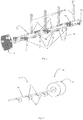
- the ramp 10, shown in negative on the figure 1 is of cylindrical shape and has an oil inlet 11 and first oil outlets 12 connected to cooling ducts to different engine components such as nozzles for example and second oil outlets 13 connected to air ducts. circulation of oil for lubricating and / or supplying oil to various members of said engine such as crankshaft bearings and crank bearings as well as the ducts of the rise to the cylinder head (not shown).
- the oil ramp 10 is continuously supplied by the oil pump.
- At least one outlet 12 of the ramp 10 is connected by a cooling duct 18 to a nozzle (not shown) installed in the wall of a cylinder in which the piston slides (not shown) and at least one output 13 of the ramp 10 opens on an oil supply conduit of the crankshaft bearings (not shown).
- the nozzles are generally intended to inject a jet of oil towards the bottom of the pistons for their cooling.
- the cooling of the various members is however not necessary at all times of operation of the engine while the lubrication must in no case stop when said engine is in operation. Note that the invention applies to single-cylinder or multicylinder engines.
- the ramp 10 comprises a flow control device 14 comprising means 15 for regulating the flow of oil to the engine components. These flow control means 15 are movably arranged in the ramp 10 to close and open at least partially at least one of the outputs 12, 13 of the ramp 10.
- the regulating device also comprises means 16 for implementing movement for setting in motion these flow control means 15 or closure of the outputs 12, 13 of the main ramp.
- the flow control means 15 comprise at least one tube 20 movable in the ramp 10 and pallets 21 carried radially by arms 22 from the tube 20.
- Said tube 20 is mounted coaxially in the main ramp 10 and has a smaller diameter to that of the main ramp.
- Said pallets 21 are preferably substantially rectangular plates arranged to seal the first outlets 12 connected to the oil circulation ducts 18 for cooling in the ramp 10 when they are positioned vis-à-vis said outputs 12.
- the second outputs 13 connected to the lubrication and / or oil supply ducts 19 are not intended to be closed by said pallets, the oil can therefore to circulate continuously in said ducts.
- the tube 20 is mounted to pivot about its axis of revolution in the ramp 10 substantially by a quarter of a turn to cause the vanes 21 to pivot in sliding on the wall of the ramp 10, to close off or clear at least one orifice 12 of the ramp 10 connected to the cooling duct 18.
- Said tube 20 is connected at one end to displacement means 16 which according to the proposed example consists of a rotation or a pivoting.
- the tube 20 is preferably steel obtained by molding with a diameter of the order of 5 mm but which may vary depending on the engine. Other materials can of course be considered, such as a plastic that can withstand the pressure and temperatures in the engine.
- the flow control is obtained by moving the tube 20 inside the ramp 10 so that the outputs 12 of the ramp 10 are closed by said vanes 21 when for example the engine is still cold and does not require cooling of the However, when the engine is hot, the temperatures of said bodies reaching thresholds too high, oil must be injected to said bodies for cooling.
- the oil pump sends oil at higher pressure to the main boom 10 and the outlets 12 connected to the cooling ducts 18 must be released for the flow of oil to these bodies.
- this solution makes it possible to manage the flow rate of the nozzles as a function of the pressure drop at the passages opposite the outlets 12 of the main ramp 10.
- Said displacement means 16 for rotating or pivoting the regulating means 15 comprise an actuating member 30 calibrated with the oil pressure flowing in the circuit.
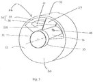
- Said displacement means 16 represented in figures 1 and 3 may comprise an actuating tube 31 whose diameter is substantially smaller than the inside diameter of the ramp 10 and rotatably mounted in a substantially cylindrical reservoir element 32, the actuating tube 31 is preferably mounted coaxially with the ramp main and movable pivotally in said ramp and intended to cooperate with the tube 20 of the regulating means 15.
- the reservoir element 32 comprises a casing 33 substantially in the form of a solid cylinder comprising an actuating chamber 34 and an axial circular opening 35, the diameter of said axial opening 35 being substantially equal to the diameter of the actuating tube 31 to surround said actuating tube with a very small clearance.
- the actuating chamber 34 is formed substantially by a cylinder quarter extending from the circular opening, said cylinder quarter is closed by two walls at the axial ends. Said actuating chamber 34 thus extends longitudinally over a length substantially shorter than the length of the reservoir element 32 and angularly over an arc of greater than 45 ° and less than 180 °.
- the actuating tube 31 comprises an outer circular wall 36 and at least one substantially radial separation wall 37 extending longitudinally on said outer circular wall 36 of the actuating tube and adapted to share the actuating chamber 34 in two parts.
- actuator 38, 39 sealed from one another.
- the actuating tube 31 has a radial opening 40 opening on one side and near the partition wall 37 in a first actuating portion 38.
- the tube 20 of the control means is preferably pressed into the actuating tube 31 and welded in said tube 31 so that the rotation of the actuating tube causes the rotation of the tube 20 of the control means.
- an elastic means 41 adapted to push the partition wall 36 so as to increase the volume of the second actuating portion 39 where said elastic means is positioned.
- the stiffness of the elastic means 41 is chosen as a function of the levels of the pressure of the oil.
- the actuating means 16 is placed at one end of the main ramp 10 so that the actuating tube 31 is coupled to the tube 20 of the regulation means inserted in the main ramp 10 and that the inside of the tube actuation 31 is in the extension of the oil circuit.
- the casing 33, the actuating tube 31 with the separating sheet 32 may be made of steel or plastic obtained by molding for example.
- Oil is injected into the main ramp, then arrives in the actuating tube 31 and passes through the radial opening 40 in the actuating tube 31 for filling the first portion 38 of the actuating chamber 34.
- the stiffness of the elastic means 41 of the actuating means is such that from a certain oil pressure level, the elastic means retracts and the partition wall 37 is moved in the direction of the reduction of the second portion 39 of the actuating chamber. This movement is reflected by a rotation of the actuating tube 31 rotatable in the ramp 10 and thus by a rotation of the tube 20 causing an opening or closing of the outlets 12 connected to the cooling ducts 18.
- the operation of the actuating means is simple and does not require an additional source of energy.
- the pivoting can be converted into a longitudinal translation movement along the axis of the main ramp of the cylindrical tube 20 of the regulating means.
Landscapes
- Engineering & Computer Science (AREA)
- Mechanical Engineering (AREA)
- General Engineering & Computer Science (AREA)
- Lubrication Of Internal Combustion Engines (AREA)
Claims (9)
- Ölkreislauf für einen Verbrennungsmotor, wobei der Kreislauf eine zylindrische Rampe (10) umfasst, welche einen Öleinlass (11) und Ölauslässe (12, 13) aufweist, um verschiedenen Elemente des Motors zu versorgen, und ein System zur Regelung des Öldurchflusses umfasst, welches Mittel zum Schließen (15) der Versorgungsauslässe (12, 13) umfasst, welche durch ein Betätigungsmittel (16) in Bewegung versetzt werden, dadurch gekennzeichnet, dass das Betätigungsmittel auf einen nominalen Druck des den Kreislauf durchströmenden Öls austariert ist und dafür geeignet ist, das Mittel zum Schließen der Auslässe zur Ölversorgung im Falle einer Überschreitung des nominalen Öldrucks in Bewegung zu versetzen.
- Ölkreislauf nach Anspruch 1, dadurch gekennzeichnet, dass das Betätigungsmittel (16) eine Kammer (38) aufweist, welche eine Öffnung (40) aufweist, die für das Öl des Kreislaufs zugänglich ist, und gegen eine Rückstellkraft drehbar montiert ist.
- Ölkreislauf nach einem der Ansprüche 1 oder 2, dadurch gekennzeichnet, dass das Betätigungsmittel (16) an einem Ende der Ölrampe angeordnet ist.
- Ölkreislauf nach einem der Ansprüche 1 bis 3, dadurch gekennzeichnet, dass das Betätigungsmittel (16) dafür geeignet ist, ein zylindrisches Betätigungsrohr (31), welches mit den Schließmitteln verbunden ist, drehen zu lassen.
- Ölkreislauf nach Anspruch 4, dadurch gekennzeichnet, dass die Mittel (15) zum Schließen der Auslässe zur Ölversorgung (12, 13) ein zylindrische Rohr (20) umfassen, welches koaxial zu der Rampe und mit dem Betätigungsrohr (31) verbunden ist.
- Ölkreislauf nach Anspruch 5, dadurch gekennzeichnet, dass das zylindrische Rohr (20) der Schließmittel (15) durch Arme (22) verlängert ist, welche Scheiben (21) tragen, die dafür angepasst sind, mindestens einen der Auslässe (12) zur Ölversorgung zumindest teilweise zu schließen und zu öffnen.
- Ölkreislauf nach Anspruch 6, dadurch gekennzeichnet, dass die Scheiben (21) dafür angepasst sind, auf der Wand der Hauptrampe (10) zu gleiten.
- Ölkreislauf nach einem der Ansprüche 1 bis 7, dadurch gekennzeichnet, dass die Schließmittel (15) in der Rampe (10) drehbar und/oder verschiebbar beweglich sind.
- Gehäuse eines Verbrennungsmotors eines Kraftfahrzeugs, dadurch gekennzeichnet, dass es mindestens einen Ölkreislauf nach einem der Ansprüche 1 bis 8 aufweist.
Applications Claiming Priority (2)
| Application Number | Priority Date | Filing Date | Title |
|---|---|---|---|
| FR1351293A FR3002275B1 (fr) | 2013-02-15 | 2013-02-15 | Circuit d'huile pour moteur a combustion interne avec moyen d'actionnement optimise |
| PCT/FR2014/050311 WO2014125230A1 (fr) | 2013-02-15 | 2014-02-14 | Circuit d'huile pour moteur a combustion interne avec moyen d'actionnement optimise |
Publications (2)
| Publication Number | Publication Date |
|---|---|
| EP2956637A1 EP2956637A1 (de) | 2015-12-23 |
| EP2956637B1 true EP2956637B1 (de) | 2017-03-29 |
Family
ID=49474494
Family Applications (1)
| Application Number | Title | Priority Date | Filing Date |
|---|---|---|---|
| EP14710014.3A Active EP2956637B1 (de) | 2013-02-15 | 2014-02-14 | Ölkreislauf für einen verbrennungsmotor mit optimiertem betätigungsmittel |
Country Status (3)
| Country | Link |
|---|---|
| EP (1) | EP2956637B1 (de) |
| FR (1) | FR3002275B1 (de) |
| WO (1) | WO2014125230A1 (de) |
Family Cites Families (6)
| Publication number | Priority date | Publication date | Assignee | Title |
|---|---|---|---|---|
| GB286088A (en) * | 1927-03-02 | 1928-03-01 | William Howell Peacey | Improvements in the lubrication of fluid pressure engines |
| GB594787A (en) * | 1944-02-24 | 1947-11-19 | Sulzer Freres Soclete Anonyme | Improvements relating to pressure responsive valves |
| JPH08270443A (ja) * | 1995-04-03 | 1996-10-15 | Nissan Motor Co Ltd | 内燃機関のピストン冷却装置 |
| US20050120982A1 (en) * | 2003-12-09 | 2005-06-09 | Detroit Diesel Corporation | Separate oil gallery for piston cooling with electronic oil flow control |
| GB2480474B (en) * | 2010-05-20 | 2016-10-05 | Ford Global Tech Llc | An oil supply system for an engine |
| FR2973070B1 (fr) | 2011-03-24 | 2015-04-17 | Renault Sa | Systeme d'alimentation en huile d'un moteur a combustion interne. |
-
2013
- 2013-02-15 FR FR1351293A patent/FR3002275B1/fr not_active Expired - Fee Related
-
2014
- 2014-02-14 WO PCT/FR2014/050311 patent/WO2014125230A1/fr not_active Ceased
- 2014-02-14 EP EP14710014.3A patent/EP2956637B1/de active Active
Also Published As
| Publication number | Publication date |
|---|---|
| FR3002275A1 (fr) | 2014-08-22 |
| FR3002275B1 (fr) | 2015-02-20 |
| EP2956637A1 (de) | 2015-12-23 |
| WO2014125230A1 (fr) | 2014-08-21 |
Similar Documents
| Publication | Publication Date | Title |
|---|---|---|
| EP2801707B1 (de) | Schmierkreislauf eines Turbotriebwerks mit Überlaufventil für Windmilling | |
| EP2486262B1 (de) | Schaltung zur zuführung von kraftstoff an ein flugzeugtriebwerk | |
| EP1750964B1 (de) | Funktionelle anordnung für ein kraftfahrzeug mit nasskupplungsgetriebeelement und einem hydrauliksystem sowie kraftfahrzeug damit | |
| CA2923212C (fr) | Dispositif d'alimentation en fluide hydraulique d'un verin et mecanisme de commande de pas des pales d'une helice de turbomoteur comportant le verin | |
| FR2955168A1 (fr) | Vanne de commande pour circuit de circulation de liquide | |
| EP2818651B1 (de) | Kolbengesteuertes Überlaufventil | |
| EP2156029A1 (de) | Modul für den kühlkreislauf eines motors in einem kraftfahrzeug | |
| WO2015185856A1 (fr) | Système d'alimentation de turbomachine en fluide avec un ensemble de pompage basse pression comprenant deux pompes en parallèle | |
| CA2492844C (fr) | Actionneur hydraulique de soupapes pour moteur a pistons | |
| FR3023319B1 (fr) | Dispositif d'alimentation en huile pour le refroidissement des pistons d'un moteur a combustion interne | |
| WO2014125230A1 (fr) | Circuit d'huile pour moteur a combustion interne avec moyen d'actionnement optimise | |
| FR2980519A1 (fr) | Circuit d'huile pour moteur a combustion interne | |
| EP1977096B1 (de) | Vorrichtung zur beschleuningung der erhöhung der schmieröltemperatur eines verbrennungsmotors mit einem abgas-turbolader | |
| FR3031135B1 (fr) | Machine de detente axiale a pistons | |
| FR3054622A1 (fr) | Ensemble piston bielle rotulee avec passage d’huile par une contre-rotule | |
| EP2758647B1 (de) | Kühlung eines elektromotors über wärmerohre | |
| EP2551525B1 (de) | Ölpumpe mit variablem Durchsatz, die ein Reguliersystem für den Öldruck in Abhängigkeit von der Temperatur umfasst | |
| EP3478945B1 (de) | Schmierung von nockenrücken durch ölrückgewinnung | |
| FR3035155A1 (fr) | Circuit de distribution de carburant de turbomachine a encombrement reduit | |
| FR3108952A1 (fr) | Ensemble pour turbomachine d’aeronef comportant un systeme ameliore de lubrification d’un reducteur d’entrainement de soufflante | |
| EP3290753B1 (de) | Anordnung aus kolben und kugelkopf-pleuelstange mit steigerung der ölströmungsgeschwindigkeit im innern | |
| FR3066538A1 (fr) | Dispositif de controle de la distribution d'huile pour un moteur thermique | |
| WO2017081142A1 (fr) | Système de motorisation et véhicule automobile associé | |
| WO2017203116A1 (fr) | Groupe motopropulseur d'un vehicule | |
| FR2711392A1 (fr) | Circuit de lubrification pour moteur à combustion interne. |
Legal Events
| Date | Code | Title | Description |
|---|---|---|---|
| PUAI | Public reference made under article 153(3) epc to a published international application that has entered the european phase |
Free format text: ORIGINAL CODE: 0009012 |
|
| 17P | Request for examination filed |
Effective date: 20150610 |
|
| AK | Designated contracting states |
Kind code of ref document: A1 Designated state(s): AL AT BE BG CH CY CZ DE DK EE ES FI FR GB GR HR HU IE IS IT LI LT LU LV MC MK MT NL NO PL PT RO RS SE SI SK SM TR |
|
| AX | Request for extension of the european patent |
Extension state: BA ME |
|
| RIN1 | Information on inventor provided before grant (corrected) |
Inventor name: RUBY, STEPHANE |
|
| DAX | Request for extension of the european patent (deleted) | ||
| GRAP | Despatch of communication of intention to grant a patent |
Free format text: ORIGINAL CODE: EPIDOSNIGR1 |
|
| INTG | Intention to grant announced |
Effective date: 20161017 |
|
| GRAS | Grant fee paid |
Free format text: ORIGINAL CODE: EPIDOSNIGR3 |
|
| STAA | Information on the status of an ep patent application or granted ep patent |
Free format text: STATUS: GRANT OF PATENT IS INTENDED |
|
| GRAA | (expected) grant |
Free format text: ORIGINAL CODE: 0009210 |
|
| STAA | Information on the status of an ep patent application or granted ep patent |
Free format text: STATUS: THE PATENT HAS BEEN GRANTED |
|
| AK | Designated contracting states |
Kind code of ref document: B1 Designated state(s): AL AT BE BG CH CY CZ DE DK EE ES FI FR GB GR HR HU IE IS IT LI LT LU LV MC MK MT NL NO PL PT RO RS SE SI SK SM TR |
|
| REG | Reference to a national code |
Ref country code: GB Ref legal event code: FG4D Free format text: NOT ENGLISH |
|
| REG | Reference to a national code |
Ref country code: CH Ref legal event code: EP |
|
| REG | Reference to a national code |
Ref country code: AT Ref legal event code: REF Ref document number: 879990 Country of ref document: AT Kind code of ref document: T Effective date: 20170415 |
|
| REG | Reference to a national code |
Ref country code: IE Ref legal event code: FG4D Free format text: LANGUAGE OF EP DOCUMENT: FRENCH |
|
| REG | Reference to a national code |
Ref country code: DE Ref legal event code: R096 Ref document number: 602014008092 Country of ref document: DE |
|
| PG25 | Lapsed in a contracting state [announced via postgrant information from national office to epo] |
Ref country code: GR Free format text: LAPSE BECAUSE OF FAILURE TO SUBMIT A TRANSLATION OF THE DESCRIPTION OR TO PAY THE FEE WITHIN THE PRESCRIBED TIME-LIMIT Effective date: 20170630 Ref country code: LT Free format text: LAPSE BECAUSE OF FAILURE TO SUBMIT A TRANSLATION OF THE DESCRIPTION OR TO PAY THE FEE WITHIN THE PRESCRIBED TIME-LIMIT Effective date: 20170329 Ref country code: FI Free format text: LAPSE BECAUSE OF FAILURE TO SUBMIT A TRANSLATION OF THE DESCRIPTION OR TO PAY THE FEE WITHIN THE PRESCRIBED TIME-LIMIT Effective date: 20170329 Ref country code: HR Free format text: LAPSE BECAUSE OF FAILURE TO SUBMIT A TRANSLATION OF THE DESCRIPTION OR TO PAY THE FEE WITHIN THE PRESCRIBED TIME-LIMIT Effective date: 20170329 Ref country code: NO Free format text: LAPSE BECAUSE OF FAILURE TO SUBMIT A TRANSLATION OF THE DESCRIPTION OR TO PAY THE FEE WITHIN THE PRESCRIBED TIME-LIMIT Effective date: 20170629 |
|
| REG | Reference to a national code |
Ref country code: NL Ref legal event code: MP Effective date: 20170329 |
|
| REG | Reference to a national code |
Ref country code: AT Ref legal event code: MK05 Ref document number: 879990 Country of ref document: AT Kind code of ref document: T Effective date: 20170329 |
|
| PG25 | Lapsed in a contracting state [announced via postgrant information from national office to epo] |
Ref country code: LV Free format text: LAPSE BECAUSE OF FAILURE TO SUBMIT A TRANSLATION OF THE DESCRIPTION OR TO PAY THE FEE WITHIN THE PRESCRIBED TIME-LIMIT Effective date: 20170329 Ref country code: BG Free format text: LAPSE BECAUSE OF FAILURE TO SUBMIT A TRANSLATION OF THE DESCRIPTION OR TO PAY THE FEE WITHIN THE PRESCRIBED TIME-LIMIT Effective date: 20170629 Ref country code: SE Free format text: LAPSE BECAUSE OF FAILURE TO SUBMIT A TRANSLATION OF THE DESCRIPTION OR TO PAY THE FEE WITHIN THE PRESCRIBED TIME-LIMIT Effective date: 20170329 Ref country code: RS Free format text: LAPSE BECAUSE OF FAILURE TO SUBMIT A TRANSLATION OF THE DESCRIPTION OR TO PAY THE FEE WITHIN THE PRESCRIBED TIME-LIMIT Effective date: 20170329 |
|
| PG25 | Lapsed in a contracting state [announced via postgrant information from national office to epo] |
Ref country code: NL Free format text: LAPSE BECAUSE OF FAILURE TO SUBMIT A TRANSLATION OF THE DESCRIPTION OR TO PAY THE FEE WITHIN THE PRESCRIBED TIME-LIMIT Effective date: 20170329 |
|
| PG25 | Lapsed in a contracting state [announced via postgrant information from national office to epo] |
Ref country code: EE Free format text: LAPSE BECAUSE OF FAILURE TO SUBMIT A TRANSLATION OF THE DESCRIPTION OR TO PAY THE FEE WITHIN THE PRESCRIBED TIME-LIMIT Effective date: 20170329 Ref country code: AT Free format text: LAPSE BECAUSE OF FAILURE TO SUBMIT A TRANSLATION OF THE DESCRIPTION OR TO PAY THE FEE WITHIN THE PRESCRIBED TIME-LIMIT Effective date: 20170329 Ref country code: SK Free format text: LAPSE BECAUSE OF FAILURE TO SUBMIT A TRANSLATION OF THE DESCRIPTION OR TO PAY THE FEE WITHIN THE PRESCRIBED TIME-LIMIT Effective date: 20170329 Ref country code: CZ Free format text: LAPSE BECAUSE OF FAILURE TO SUBMIT A TRANSLATION OF THE DESCRIPTION OR TO PAY THE FEE WITHIN THE PRESCRIBED TIME-LIMIT Effective date: 20170329 Ref country code: ES Free format text: LAPSE BECAUSE OF FAILURE TO SUBMIT A TRANSLATION OF THE DESCRIPTION OR TO PAY THE FEE WITHIN THE PRESCRIBED TIME-LIMIT Effective date: 20170329 Ref country code: RO Free format text: LAPSE BECAUSE OF FAILURE TO SUBMIT A TRANSLATION OF THE DESCRIPTION OR TO PAY THE FEE WITHIN THE PRESCRIBED TIME-LIMIT Effective date: 20170329 |
|
| PG25 | Lapsed in a contracting state [announced via postgrant information from national office to epo] |
Ref country code: SM Free format text: LAPSE BECAUSE OF FAILURE TO SUBMIT A TRANSLATION OF THE DESCRIPTION OR TO PAY THE FEE WITHIN THE PRESCRIBED TIME-LIMIT Effective date: 20170329 Ref country code: PL Free format text: LAPSE BECAUSE OF FAILURE TO SUBMIT A TRANSLATION OF THE DESCRIPTION OR TO PAY THE FEE WITHIN THE PRESCRIBED TIME-LIMIT Effective date: 20170329 Ref country code: IS Free format text: LAPSE BECAUSE OF FAILURE TO SUBMIT A TRANSLATION OF THE DESCRIPTION OR TO PAY THE FEE WITHIN THE PRESCRIBED TIME-LIMIT Effective date: 20170729 |
|
| REG | Reference to a national code |
Ref country code: DE Ref legal event code: R097 Ref document number: 602014008092 Country of ref document: DE |
|
| PG25 | Lapsed in a contracting state [announced via postgrant information from national office to epo] |
Ref country code: DK Free format text: LAPSE BECAUSE OF FAILURE TO SUBMIT A TRANSLATION OF THE DESCRIPTION OR TO PAY THE FEE WITHIN THE PRESCRIBED TIME-LIMIT Effective date: 20170329 |
|
| PLBE | No opposition filed within time limit |
Free format text: ORIGINAL CODE: 0009261 |
|
| STAA | Information on the status of an ep patent application or granted ep patent |
Free format text: STATUS: NO OPPOSITION FILED WITHIN TIME LIMIT |
|
| REG | Reference to a national code |
Ref country code: FR Ref legal event code: PLFP Year of fee payment: 5 |
|
| PG25 | Lapsed in a contracting state [announced via postgrant information from national office to epo] |
Ref country code: IT Free format text: LAPSE BECAUSE OF FAILURE TO SUBMIT A TRANSLATION OF THE DESCRIPTION OR TO PAY THE FEE WITHIN THE PRESCRIBED TIME-LIMIT Effective date: 20170329 |
|
| 26N | No opposition filed |
Effective date: 20180103 |
|
| PG25 | Lapsed in a contracting state [announced via postgrant information from national office to epo] |
Ref country code: SI Free format text: LAPSE BECAUSE OF FAILURE TO SUBMIT A TRANSLATION OF THE DESCRIPTION OR TO PAY THE FEE WITHIN THE PRESCRIBED TIME-LIMIT Effective date: 20170329 |
|
| REG | Reference to a national code |
Ref country code: CH Ref legal event code: PL |
|
| PG25 | Lapsed in a contracting state [announced via postgrant information from national office to epo] |
Ref country code: MC Free format text: LAPSE BECAUSE OF FAILURE TO SUBMIT A TRANSLATION OF THE DESCRIPTION OR TO PAY THE FEE WITHIN THE PRESCRIBED TIME-LIMIT Effective date: 20170329 Ref country code: MT Free format text: LAPSE BECAUSE OF FAILURE TO SUBMIT A TRANSLATION OF THE DESCRIPTION OR TO PAY THE FEE WITHIN THE PRESCRIBED TIME-LIMIT Effective date: 20170329 |
|
| REG | Reference to a national code |
Ref country code: IE Ref legal event code: MM4A |
|
| REG | Reference to a national code |
Ref country code: BE Ref legal event code: MM Effective date: 20180228 |
|
| PG25 | Lapsed in a contracting state [announced via postgrant information from national office to epo] |
Ref country code: LI Free format text: LAPSE BECAUSE OF NON-PAYMENT OF DUE FEES Effective date: 20180228 Ref country code: CH Free format text: LAPSE BECAUSE OF NON-PAYMENT OF DUE FEES Effective date: 20180228 Ref country code: LU Free format text: LAPSE BECAUSE OF NON-PAYMENT OF DUE FEES Effective date: 20180214 |
|
| PG25 | Lapsed in a contracting state [announced via postgrant information from national office to epo] |
Ref country code: IE Free format text: LAPSE BECAUSE OF NON-PAYMENT OF DUE FEES Effective date: 20180214 |
|
| PG25 | Lapsed in a contracting state [announced via postgrant information from national office to epo] |
Ref country code: BE Free format text: LAPSE BECAUSE OF NON-PAYMENT OF DUE FEES Effective date: 20180228 |
|
| PG25 | Lapsed in a contracting state [announced via postgrant information from national office to epo] |
Ref country code: TR Free format text: LAPSE BECAUSE OF FAILURE TO SUBMIT A TRANSLATION OF THE DESCRIPTION OR TO PAY THE FEE WITHIN THE PRESCRIBED TIME-LIMIT Effective date: 20170329 |
|
| PG25 | Lapsed in a contracting state [announced via postgrant information from national office to epo] |
Ref country code: PT Free format text: LAPSE BECAUSE OF FAILURE TO SUBMIT A TRANSLATION OF THE DESCRIPTION OR TO PAY THE FEE WITHIN THE PRESCRIBED TIME-LIMIT Effective date: 20170329 |
|
| PG25 | Lapsed in a contracting state [announced via postgrant information from national office to epo] |
Ref country code: HU Free format text: LAPSE BECAUSE OF FAILURE TO SUBMIT A TRANSLATION OF THE DESCRIPTION OR TO PAY THE FEE WITHIN THE PRESCRIBED TIME-LIMIT; INVALID AB INITIO Effective date: 20140214 Ref country code: MK Free format text: LAPSE BECAUSE OF NON-PAYMENT OF DUE FEES Effective date: 20170329 Ref country code: CY Free format text: LAPSE BECAUSE OF FAILURE TO SUBMIT A TRANSLATION OF THE DESCRIPTION OR TO PAY THE FEE WITHIN THE PRESCRIBED TIME-LIMIT Effective date: 20170329 |
|
| PG25 | Lapsed in a contracting state [announced via postgrant information from national office to epo] |
Ref country code: AL Free format text: LAPSE BECAUSE OF FAILURE TO SUBMIT A TRANSLATION OF THE DESCRIPTION OR TO PAY THE FEE WITHIN THE PRESCRIBED TIME-LIMIT Effective date: 20170329 |
|
| P01 | Opt-out of the competence of the unified patent court (upc) registered |
Effective date: 20230608 |
|
| REG | Reference to a national code |
Ref country code: GB Ref legal event code: 732E Free format text: REGISTERED BETWEEN 20231228 AND 20240103 |
|
| REG | Reference to a national code |
Ref country code: DE Ref legal event code: R081 Ref document number: 602014008092 Country of ref document: DE Owner name: NEW H POWERTRAIN HOLDING, S.L.U., ES Free format text: FORMER OWNER: RENAULT S.A.S., BOULOGNE-BILLANCOURT, FR |
|
| PGFP | Annual fee paid to national office [announced via postgrant information from national office to epo] |
Ref country code: GB Payment date: 20260219 Year of fee payment: 13 |
|
| PGFP | Annual fee paid to national office [announced via postgrant information from national office to epo] |
Ref country code: DE Payment date: 20260218 Year of fee payment: 13 |
|
| PGFP | Annual fee paid to national office [announced via postgrant information from national office to epo] |
Ref country code: FR Payment date: 20260218 Year of fee payment: 13 |