EP2956710B1 - Längliche leuchte - Google Patents
Längliche leuchte Download PDFInfo
- Publication number
- EP2956710B1 EP2956710B1 EP14716246.5A EP14716246A EP2956710B1 EP 2956710 B1 EP2956710 B1 EP 2956710B1 EP 14716246 A EP14716246 A EP 14716246A EP 2956710 B1 EP2956710 B1 EP 2956710B1
- Authority
- EP
- European Patent Office
- Prior art keywords
- cover
- layer
- luminaire
- carrier
- light
- Prior art date
- Legal status (The legal status is an assumption and is not a legal conclusion. Google has not performed a legal analysis and makes no representation as to the accuracy of the status listed.)
- Not-in-force
Links
Images



Classifications
-
- F—MECHANICAL ENGINEERING; LIGHTING; HEATING; WEAPONS; BLASTING
- F21—LIGHTING
- F21S—NON-PORTABLE LIGHTING DEVICES; SYSTEMS THEREOF; VEHICLE LIGHTING DEVICES SPECIALLY ADAPTED FOR VEHICLE EXTERIORS
- F21S4/00—Lighting devices or systems using a string or strip of light sources
- F21S4/20—Lighting devices or systems using a string or strip of light sources with light sources held by or within elongate supports
- F21S4/28—Lighting devices or systems using a string or strip of light sources with light sources held by or within elongate supports rigid, e.g. LED bars
-
- F—MECHANICAL ENGINEERING; LIGHTING; HEATING; WEAPONS; BLASTING
- F21—LIGHTING
- F21V—FUNCTIONAL FEATURES OR DETAILS OF LIGHTING DEVICES OR SYSTEMS THEREOF; STRUCTURAL COMBINATIONS OF LIGHTING DEVICES WITH OTHER ARTICLES, NOT OTHERWISE PROVIDED FOR
- F21V3/00—Globes; Bowls; Cover glasses
- F21V3/04—Globes; Bowls; Cover glasses characterised by materials, surface treatments or coatings
- F21V3/06—Globes; Bowls; Cover glasses characterised by materials, surface treatments or coatings characterised by the material
- F21V3/062—Globes; Bowls; Cover glasses characterised by materials, surface treatments or coatings characterised by the material the material being plastics
- F21V3/0625—Globes; Bowls; Cover glasses characterised by materials, surface treatments or coatings characterised by the material the material being plastics the material diffusing light, e.g. translucent plastics
-
- F—MECHANICAL ENGINEERING; LIGHTING; HEATING; WEAPONS; BLASTING
- F21—LIGHTING
- F21V—FUNCTIONAL FEATURES OR DETAILS OF LIGHTING DEVICES OR SYSTEMS THEREOF; STRUCTURAL COMBINATIONS OF LIGHTING DEVICES WITH OTHER ARTICLES, NOT OTHERWISE PROVIDED FOR
- F21V3/00—Globes; Bowls; Cover glasses
- F21V3/04—Globes; Bowls; Cover glasses characterised by materials, surface treatments or coatings
- F21V3/10—Globes; Bowls; Cover glasses characterised by materials, surface treatments or coatings characterised by coatings
-
- F—MECHANICAL ENGINEERING; LIGHTING; HEATING; WEAPONS; BLASTING
- F21—LIGHTING
- F21Y—INDEXING SCHEME ASSOCIATED WITH SUBCLASSES F21K, F21L, F21S and F21V, RELATING TO THE FORM OR THE KIND OF THE LIGHT SOURCES OR OF THE COLOUR OF THE LIGHT EMITTED
- F21Y2105/00—Planar light sources
- F21Y2105/10—Planar light sources comprising a two-dimensional [2D] array of point-like light-generating elements
-
- F—MECHANICAL ENGINEERING; LIGHTING; HEATING; WEAPONS; BLASTING
- F21—LIGHTING
- F21Y—INDEXING SCHEME ASSOCIATED WITH SUBCLASSES F21K, F21L, F21S and F21V, RELATING TO THE FORM OR THE KIND OF THE LIGHT SOURCES OR OF THE COLOUR OF THE LIGHT EMITTED
- F21Y2115/00—Light-generating elements of semiconductor light sources
- F21Y2115/10—Light-emitting diodes [LED]
Definitions
- the invention relates to an elongated lamp.
- the Applicant sells an elongated luminaire under the name SLOTLIGHT II.
- This luminaire comprises a profile-like, in cross-section in a first approximation U-shaped, aluminum channel element and an elongated, translucent plastic cover which is snapped into the channel element and through which a plane, light-emitting Surface of the lamp is formed.
- an end cap is placed in each case.
- the end caps serve to conceal these different longitudinal changes.
- the end caps also lead to the appearance of the luminaire when viewed on the light-emitting surface edge is uneven.
- the longitudinal edges of the light-emitting surface appear differently than the front edges of the end caps.
- the lamp From the DE 81 28 057 U1 is a lamp with a, a light exit opening occlusive diffuser wall and a housing side wall known. Furthermore, the lamp has a housing rear side, which is fastened to the housing side walls.
- the housing side walls are made of a plastic and are provided with a reflective layer.
- thermoplastic sheet for use as a light scattering protective cover for LED light sources.
- FR 2 122 501 A1 From the FR 2 122 501 A1 is an elongated lamp with a support and a cover known.
- the cover has a laterally encircling wall portion and at its upper edge grooves which engage for support in ribs formed on the support.
- the invention has for its object to provide an elongated lamp that allows a particularly uniform appearance.
- the luminaire is intended to make it possible that, when viewing the light-emitting surface, the edge of this surface appears to be particularly uniform all around.
- a luminaire having an elongated cover with a planar light emission surface extending in a plane, and an elongated support, the cover being mounted on the support.
- the cover has a lateral wall area, which is closed circumferential shape immediately adjoins the light emitting surface. In this case, a light-tight layer is applied to the lateral wall region.
- the cover is made of plastic and the support of metal.
- the edge of the light emission surface has a uniform appearance on all sides; there are no end caps required, because due to the lateral wall portion of the carrier does not have to extend to the light emitting surface. Due to the light-tight layer on the lateral wall area, the edge can be made to appear particularly clear and precise. It can almost cause a "frameless" appearing light delivery surface.
- the layer consists of a metal and the cover for example of PMMA (polymethyl methacrylate).
- PMMA polymethyl methacrylate
- the layer is formed by a film and / or by a lacquer.
- the layer can be made very thin and thus the edge of the light emitting surface defined particularly sharp, so to speak, like a line.
- the layer may be formed by coextrusion with the cover.
- the layer is designed to be reflective. As a result, a particularly good efficiency can be achieved for the lamp.
- the cover is shaped so that the side wall portion and the light emitting surface enclose an angle of 90 ° on all sides. This makes it possible to achieve that, when the luminaire is viewed against the normal of the light emission surface, only the light emission surface is visible. This can cause a particularly high-quality impression of the lamp.
- the cover is shaped so that a parallelepiped shape is defined by the light emitting surface and the lateral wall portion.
- the light emission surface can be designed in a particularly straight shape in the form of a straight line.
- the lamp is designed such that the carrier is completely covered by the cover when viewing the lamp against the normal of the light emitting surface. This also makes it possible to make the outer appearance of the lamp advantageous particularly high-quality acting.
- the cover is slidably suspended on the carrier.
- a light source in particular in the form of LEDs (LED: light emitting diode) is supported on the support, wherein the lamp is designed so that a light emitted from the light source passes through the light emitting surface and is discharged into an outer space of the lamp.
- LED light emitting diode
- the carrier forms a surface region of the lamp, wherein in particular the carrier is designed as a heat sink for the light source of the lamp.
- the cover is formed in the region of the light emission surface with a first layer and a second layer, the first layer being diffuse and the second layer being clear.
- the first layer and the second layer are advantageously formed by coextrusion.
- the luminaire has a length which is greater than 3 m, in particular greater than 5 m.
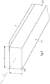
- Fig. 1 shows a perspective sketch of a longitudinal region of a lamp according to the invention.
- the luminaire is overall elongated, so that it extends along a longitudinal axis L.
- the luminaire has an elongate cover 2 which extends along the longitudinal axis L.
- Fig. 5 is shown a sketch to a cross section normal to the longitudinal axis.
- the cover 2 has a light emitting surface 21 which is flat and extends in a plane E.
- the cover 2 is preferably formed in one piece. In this way, the light emission surface 21 can be designed quasi "seamlessly", in particular over the entire longitudinal extension of the cover 2.
- the plane E extends horizontally when the luminaire is aligned, as intended for operation relative to the vertical, with the cover 2 extending from the plane E upwards.
- this orientation of the luminaire is assumed below. In general, however, the luminaire can also be oriented elsewhere.
- the lamp has an elongate carrier 3, which also extends along the longitudinal axis L, wherein the cover 2 is arranged supported on the carrier 3.
- the cover 2 is made of a plastic, such as PMMA.
- the carrier 3 consists of a metal, for example aluminum.
- the lamp is designed very long, so more than three meters, preferably more than five meters. For example, it has a length of up to eight meters. The longer the luminaire is, the more the length changes that are caused by temperature fluctuations generally have an effect.
- the cover 2 extends over the entire length of the lamp while the carrier 3 is slightly shorter than the cover 2 is designed.
- FIG. 2 and 3 two perspective views are sketched on an end portion of the lamp.
- the design is preferably such that with respect to the longitudinal axis L, the cover 2 extends beyond the support 3 at its two end regions. This makes it possible that in the case of a temperature-related shortening of the cover 2 does not happen that - when viewing the lamp against the normal of the light emitting surface 21, so as in Fig. 5 indicated by an arrow p - the carrier 3 is visible at one of the two end portions.
- the cover 2 also has a lateral wall region 22, which adjoins the light emission surface 21 in a closed circumferential shape.
- the cover 2 is shaped such that the lateral wall region 22 and the light emission surface 21 enclose an angle of 90 ° on all sides.
- the cover 2 is preferably shaped such that a parallelepiped shape is defined by the light emission surface 21 and the lateral wall region 22.
- the design may be, for example, such that the cuboid or the cover 2 has a width b measured transversely to the longitudinal axis L , which is between 50 mm and 200 mm, that is, for example 100 mm, and one perpendicular to the longitudinal axis L and to the direction of the width b standing height h, which is between 30 mm and 150 mm, so for example 50 mm or 60 mm.
- the design is furthermore such that the support 3 also extends less far with respect to the width b than the cover 2, so that the cover 2 also extends beyond the support 3 along this widthwise extension.
- the lamp is designed so that the carrier 3 is completely covered by the cover 2 when viewing the lamp normal to or to the light emitting surface 21.
- the carrier 3 is concentrically offset with respect to the cover 2 inwards.
- the lamp is further designed so that in the above-mentioned consideration of the lamp, no other parts of the luminaire next to the light emitting surface 21 are visible.
- a light-tight layer 4 is applied on the lateral wall portion 22, a light-tight layer 4 is applied.
- the layer 4 is preferably designed to form a peripheral edge of the light emitting surface 21.
- the layer 4 thus extends annularly closed along the entire lateral wall region 22.
- the design is such that the lateral wall region 22 is completely covered by the layer 4.
- the layer 4 extends advantageously over the entire height h, the entire width b and the entire Length of the cover 2.
- the layer 4 extends over all vertical wall portions of the cover 2.
- a light-tight lamination can be formed by the layer 4.
- the layer 4 may be formed for example by a film, in particular by a metal foil.
- the film can be applied to the lateral wall region 22, for example, by means of a foil embossing.
- the layer 4 may be formed by a lacquer, in particular in the form of a permanently elastic coating.
- the layer 4 may be formed together with the cover 2 by a coextrusion, so that in this way a quasi, a light-tight side web is formed.
- the layer 4 is designed such that it has a particularly low thickness so as to be able to make the edge of the light emitting surface 21 particularly sharp.
- a light source 5 is supported on the carrier 3.
- the light source 5 may in particular be a plurality of LEDs, which is preferably arranged in a matrix-like manner on a circuit board, which in turn is supported on the carrier 3, in particular with good heat conductivity.
- the luminaire is designed such that a light emitted by the light source 5 passes through the light emission surface 21 and is emitted into an exterior space of the luminaire.
- the light source 5 preferably represents a light source 5 for emitting light of the lamp.
- the layer 4 is designed so that it is reflective, in particular on its inner side, ie on the side facing a center of the cover 2.
- a particularly good efficiency can be achieved for the lamp.
- the carrier 3 is preferably designed so that it forms a surface region of the lamp. In particular, it can be designed as a heat sink for the light source 5.
- the cover 2 is slidably suspended from the carrier as indicated in FIG Fig. 5 shown.
- the cover 2 preferably has an inwardly facing flange region 23 at the upper edge of the lateral wall region 21, which are configured as bearing surfaces of the cover 2 for mounting on the carrier 3 along the regions which extend parallel to the longitudinal axis L. like this Fig. 6 suggestively.
- the flange region 23 only reaches as far as the carrier 3, but does not overlap it. This goes out Fig. 4 which shows a longitudinal section through the end of the lamp.
- the shape of the cover 2 can accordingly describe a total of an elongated cuboid, wherein one of the four longitudinal sides, here the upwardly facing longitudinal side, has a particular rectangular opening, which is designed for suspension on the support 3.
- At least one further lighting component for example an operating device 6 for operating the light source 5, may also be supported on the carrier 3.
- a suspension element for suspending the luminaire, for example on a ceiling, may also be provided or formed on the support 3.
- a particularly suitable light distribution on the light-emitting surface 21 can be achieved if the cover 2 is formed in the area of the light-emitting surface 21 with a first layer 211 and a second layer 212, the first layer 211 being diffuse and the second layer 212 being clear.
- the diffuse or first layer 211 may form an inner layer with respect to the center of the cover 2 and the clear or second layer 212 an outer layer.
- the first layer 211 and the second layer 212 can be formed by coextrusion for this purpose.
- the lateral wall region 22 or the remaining cover 2 may have the same material properties or optical properties as the first layer 211.
- the two mentioned layers 211, 212 may also be formed separately from one another.
- the luminaire is suitable, for example, for being installed in a ceiling with a circumferential shadow gap.
- the shadow gap can be very narrow, for example, only 13 mm.
- the light-emitting surface 21 can therefore be designed very precisely.
- the luminaire allows, as it were, a frameless appearance of the light emission surface 21.
Landscapes
- Engineering & Computer Science (AREA)
- General Engineering & Computer Science (AREA)
- Non-Portable Lighting Devices Or Systems Thereof (AREA)
Description
- Die Erfindung betrifft eine längliche Leuchte.
- Die Anmelderin vertreibt eine längliche Leuchte unter der Bezeichnung SLOTLIGHT II. Diese Leuchte umfasst ein profilartiges, im Querschnitt in erster Näherung U-förmiges, Kanalelement aus Aluminium sowie eine längliche, lichtdurchlässige Kunststoffabdeckung, die in das Kanalelement eingeschnappt ist und durch die eine plane, lichtabgebende Fläche der Leuchte gebildet ist. An den beiden Längs-Enden der Leuchte ist jeweils eine Endkappe aufgesetzt. Bei Temperaturänderungen verändern sich die Längserstreckungen des Kanalelements aus Aluminium einerseits und der Kunststoffabdeckung andererseits in unterschiedlichem Ausmaß. Die Endkappen dienen dazu, diese unterschiedlichen Längsveränderungen zu kaschieren. Die Endkappen führen allerdings auch dazu, dass das äußere Erscheinungsbild der Leuchte bei Betrachtung auf die lichtabgebende Fläche randseitig uneinheitlich ist. Die Längsränder der lichtabgebenden Fläche erscheinen anders als die stirnseitigen Ränder bei den Endkappen.
- Aus der
DE 81 28 057 U1 ist eine Leuchte mit einer, eine Lichtaustrittsöffnung verschließenden Diffusorwand und einer Gehäuseseitenwand bekannt. Weiterhin weist die Leuchte eine Gehäuserückseite auf, die an den Gehäuseseitenwänden befestigt ist. Die Gehäuseseitenwände bestehen aus einem Kunststoff und sind mit einer reflektierenden Schicht versehen. - Aus der
CH 426 006 A - Aus der
DE 603 14 566 T2 ist eine lichtdurchlässige, coextrudierte, thermoplastische Platte zur Verwendung als Licht streuende Schutzabdeckung für LED-Lichtquellen bekannt. - Aus der
FR 2 122 501 A1 - Aus der
DE 201 12 365 U1 ist eine längliche Leuchte mit einem Basisteil und einer daran gehaltenen Abdeckung bekannt. Die Abdeckung weist an ihrem oberen Rand einen Ringstutzen auf, der über eine Verrastungsvorrichtung an einem, an dem Basisteil ausgebildeten Ringvorsprung mit Bewegungsspiel gehalten ist. - Der Erfindung liegt die Aufgabe zugrunde, eine längliche Leuchte anzugeben, die ein besonders gleichmäßiges äußeres Erscheinungsbild ermöglicht. Insbesondere soll die Leuchte ermöglichen, dass bei Betrachtung der lichtabgebenden Fläche der Rand dieser Fläche umlaufend besonders gleichmäßig erscheint.
- Diese Aufgabe wird gemäß der Erfindung mit dem in dem unabhängigen Anspruch genannten Gegenstand gelöst. Besondere Ausführungsformen der Erfindung sind in den abhängigen Ansprüchen angegeben.
- Gemäß der Erfindung ist eine Leuchte vorgesehen, die eine längliche Abdeckung mit einer, in einer Ebene verlaufenden, planen Lichtabgabefläche aufweist, sowie einen länglichen Träger, wobei die Abdeckung an dem Träger gehaltert angeordnet ist. Die Abdeckung weist dabei einen seitlichen Wandbereich auf, der sich in geschlossen umlaufender Form unmittelbar an die Lichtabgabefläche anschließt. Auf dem seitlichen Wandbereich ist dabei eine lichtdichte Schicht aufgebracht. Die Abdeckung besteht aus Kunststoff und der Träger aus Metall.
- Durch den umlaufend gestalteten seitlichen Wandbereich lässt sich erzielen, dass der Rand der Lichtabgabefläche allseits ein einheitliches Erscheinungsbild aufweist; es sind keine Endkappen erforderlich, da sich aufgrund des seitlichen Wandbereichs der Träger nicht bis zu der Lichtabgabefläche hin erstrecken muss. Durch die lichtdichte Schicht auf dem seitlichen Wandbereich lässt sich der Rand dabei besonders klar und präzise erscheinend gestalten. Es lässt sich quasi eine "rahmenlos" erscheinende Lichtabgabefläche bewirken.
- Vorzugsweise besteht die Schicht aus einem Metall und die Abdeckung beispielsweise aus PMMA (Polymethylmethacrylat). Durch eine metallene Schicht auf dem seitlichen Wandbereich der Abdeckung lässt sich besonders geeignet eine lichtdichte Oberfläche auf dem seitlichen Wandbereich bilden, insbesondere wenn der seitliche Wandbereich aus Kunststoff besteht.
- Vorzugsweise ist die Schicht durch eine Folie und/oder durch einen Lack gebildet. Hierdurch lässt sich die Schicht besonders dünn gestalten und damit der Rand der Lichtabgabefläche besonders scharf definiert, sozusagen strichartig. Alternativ kann die Schicht durch eine Koextrusion zusammen mit der Abdeckung gebildet sein.
- Vorzugsweise ist die Schicht reflektierend gestaltet. Hierdurch lässt sich für die Leuchte ein besonders guter Wirkungsgrad erzielen.
- Vorzugsweise ist die Abdeckung so geformt, dass der seitliche Wandbereich und die Lichtabgabefläche allseits einen Winkel von 90° einschließen. Hierdurch lässt sich erzielen, dass bei Betrachtung der Leuchte entgegen der Normalen der Lichtabgabefläche lediglich die Lichtabgabefläche sichtbar ist. Hierdurch lässt sich ein besonders hochwertiger Eindruck der Leuchte bewirken.
- Vorzugsweise ist die Abdeckung so geformt, dass durch die Lichtabgabefläche und den seitlichen Wandbereich eine Quaderform festgelegt ist. Auf diese Weise lässt sich besonders geeignet die Lichtabgabefläche in Form einer geraden Linie gestalten.
- Vorzugsweise ist die Leuchte derart gestaltet, dass der Träger bei einer Betrachtung der Leuchte entgegen der Normalen der Lichtabgabefläche vollständig durch die Abdeckung verdeckt ist. Auch hierdurch lässt sich das äußere Erscheinungsbild der Leuchte vorteilhaft besonders hochwertig wirkend gestalten.
- Erfindungsgemäß ist die Abdeckung an dem Träger gleitend aufgehängt.
- Vorzugsweise ist an dem Träger eine Lichtquelle, insbesondere in Form von LEDs (LED: Licht emittierende Diode) gehaltert, wobei die Leuchte so gestaltet ist, dass ein von der Lichtquelle abgegebenes Licht durch die Lichtabgabefläche hindurchtritt und in einen Außenraum der Leuchte abgegeben wird. Auf diese Weise lässt sich vorteilhaft erzielen, dass das Licht der Lichtquelle gut durchmischt wird, bevor es die Lichtabgabefläche durchsetzt und somit eine besonders homogene Lichtverteilung auf der Lichtabgabefläche bewirkt wird.
- Vorzugsweise bildet der Träger einen Oberflächenbereich der Leuchte, wobei insbesondere der Träger als Kühlkörper für die Lichtquelle der Leuchte ausgestaltet ist.
- Vorzugsweise ist die Abdeckung im Bereich der Lichtabgabefläche mit einer ersten Schicht und einer zweiten Schicht ausgebildet, wobei die erste Schicht diffus und die zweite Schicht klar gestaltet ist. Dabei sind die erste Schicht und die zweite Schicht herstellungstechnisch vorteilhaft durch eine Koextrusion gebildet.
- Erfindungsgemäß weist die Leuchte eine Länge auf, die größer als 3 m, insbesondere größer als 5 m ist.
- Die Erfindung wird im Folgenden anhand eines Ausführungsbeispiels und mit Bezug auf die Zeichnungen näher erläutert. Es zeigen:
- Fig. 1
- eine perspektivische Skizze eines Längsbereichs einer erfindungsgemäßen Leuchte,
- Fig. 2
- eine perspektivische Skizze eines Endbereichs der Leuchte,
- Fig. 3
- eine weitere perspektivische Skizze des Endbereichs aus einem anderen Blickwinkel,
- Fig. 4
- einen Längsschnitt durch den Endbereich der Leuchte,
- Fig. 5
- eine Skizze zu einem Querschnitt durch die Leuchte und
- Fig. 6
- einen vergrößerten Ausschnitt aus der Zeichnung der
Fig. 5 . -
Fig. 1 zeigt eine perspektivische Skizze eines Längsbereichs einer erfindungsgemäßen Leuchte. Die Leuchte ist insgesamt länglich, so dass sie sich entlang einer Längsachse L erstreckt. Die Leuchte weist eine längliche Abdeckung 2 auf, die sich entlang der Längsachse L erstreckt. - In
Fig. 5 ist eine Skizze zu einem Querschnitt normal zu der Längsachse gezeigt. Die Abdeckung 2 weist eine Lichtabgabefläche 21 auf, die plan ist und in einer Ebene E verläuft. Die Abdeckung 2 ist vorzugsweise aus einem Stück bestehend ausgebildet. So lässt sich die Lichtabgabefläche 21 quasi "nahtlos" gestalten, insbesondere über die gesamte Längserstreckung der Abdeckung 2 hinweg. - Beispielsweise kann vorgesehen sein, dass die Ebene E horizontal verläuft, wenn die Leuchte, wie für einen Betrieb vorgesehen relativ zu der Vertikalen ausgerichtet ist, wobei sich die Abdeckung 2 von der Ebene E nach oben hin erstreckt. Im Folgenden wird der Einfachheit halber von dieser Orientierung der Leuchte ausgegangen. Im Allgemeinen kann die Leuchte aber auch anderweitig orientiert sein.
- Weiterhin weist die Leuchte einen länglichen Träger 3 auf, der sich ebenfalls entlang der Längsachse L erstreckt, wobei die Abdeckung 2 an dem Träger 3 gehaltert angeordnet ist.
- Die Abdeckung 2 besteht aus einem Kunststoff, beispielsweise aus PMMA. Der Träger 3 besteht aus einem Metall, beispielsweise aus Aluminium.
- Die Leuchte ist sehr lang gestaltet, also mehr als drei Meter, vorzugsweise mehr als fünf Meter. Beispielsweise weist sie eine Länge von bis zu acht Metern auf. Je länger die Leuchte ist, desto mehr wirken sich im Allgemeinen Längenänderungen aus, die durch Temperaturschwankungen bedingt sind. Bei der hier gezeigten Leuchte erstreckt sich die Abdeckung 2 über die gesamte Länge der Leuchte während der Träger 3 etwas kürzer als die Abdeckung 2 gestaltet ist.
- In den
Figuren 2 und3 sind zwei perspektivische Ansichten auf einen Endbereich der Leuchte skizziert. Wie in den Skizzen exemplarisch anhand des einen Endbereichs dargestellt, insbesondere inFig. 3 , die eine Ansicht von schräg oben zeigt, ist die Gestaltung vorzugsweise so, dass sich mit Bezug auf die Längsachse L die Abdeckung 2 an ihren beiden Endbereichen über den Träger 3 hinaus erstreckt. Hierdurch wird ermöglicht, dass es im Fall einer temperaturbedingten Verkürzung der Abdeckung 2 nicht dazu kommt, dass - bei Betrachtung der Leuchte entgegen der Normalen der Lichtabgabefläche 21, also so wie inFig. 5 durch einen Pfeil p angedeutet - der Träger 3 an einem der beiden Endbereiche sichtbar wird. - Die Abdeckung 2 weist weiterhin einen seitlichen Wandbereich 22 auf, der sich in geschlossen umlaufender Form unmittelbar an die Lichtabgabefläche 21 anschließt. Im gezeigten Beispiel ist die Abdeckung 2 so geformt, dass der seitliche Wandbereich 22 und die Lichtabgabefläche 21 allseits einen Winkel von 90° einschließen. Insbesondere ist die Abdeckung 2 vorzugsweise so geformt, dass durch die Lichtabgabefläche 21 und den seitlichen Wandbereich 22 eine Quaderform festgelegt ist. Im Vergleich zum eingangs erwähnten Stand der Technik sind hier also gleichsam die stirnseitigen "Endkappen" als integraler Teil der Abdeckung 2 gestaltet, bzw. solche Endkappen sind durch die beschriebene Gestaltung hinfällig.
- Die Gestaltung kann dabei beispielsweise so sein, dass der Quader bzw. die Abdeckung 2 eine, quer zu der Längsachse L gemessene Breite b aufweist, die zwischen 50 mm und 200 mm, also beispielsweise 100 mm beträgt und eine, senkrecht zu der Längsachse L und zu der Richtung der Breite b stehende Höhe h, die zwischen 30 mm und 150 mm beträgt, also beispielsweise 50 mm oder 60 mm.
- Beim gezeigten Ausführungsbeispiel ist die Gestaltung weiterhin so, dass sich der Träger 3 auch mit Bezug auf die Breite b weniger weit erstreckt als die Abdeckung 2, so dass sich auch entlang dieser Breitenerstreckung die Abdeckung 2 über den Träger 3 hinaus erstreckt. Auf diese Weise ist die Leuchte so gestaltet, dass der Träger 3 bei einer Betrachtung der Leuchte normal auf die bzw. zur Lichtabgabefläche 21, vollständig durch die Abdeckung 2 verdeckt ist. Hierdurch lässt sich erzielen, dass sich eine temperaturschwankungsbedingte Längenänderung der Abdeckung 2 für einen Betrachter praktisch nicht bemerkbar macht. Vorzugsweise ist der Träger 3 mit Bezug auf die Abdeckung 2 konzentrisch nach innen versetzt.
- Vorzugsweise ist die Leuchte weiterhin so gestaltet, dass bei der genannten Betrachtung der Leuchte auch keine anderweitigen Leuchtenteile neben der Lichtabgabefläche 21 sichtbar sind.
- Auf dem seitlichen Wandbereich 22 ist eine lichtdichte Schicht 4 aufgebracht. Dies ist beispielhaft in
Fig. 6 angedeutet, die einen Ausschnitt "A" ausFig. 5 vergrößert zeigt. Durch die lichtdichte Schicht 4 lässt sich erzielen, dass die Lichtabgabefläche 21 einen besonders klar bzw. scharf verlaufenden Rand aufweist. Dementsprechend ist die Schicht 4 vorzugsweise so gestaltet, dass sie einen umlaufenden Rand der Lichtabgabefläche 21 bildet. Die Schicht 4 erstreckt sich in diesem Fall also ringförmig geschlossen entlang des gesamten seitlichen Wandbereichs 22. In dem gezeigten Beispiel ist die Gestaltung so, dass der seitliche Wandbereich 22 vollständig mit der Schicht 4 bedeckt ist. Dementsprechend erstreckt sich in diesem Fall auch die Schicht 4 vorteilhaft über die gesamte Höhe h, die gesamte Breite b und die gesamte Länge der Abdeckung 2. Mit anderen Worten kann vorgesehen sein, dass sich die Schicht 4 über alle senkrechten Wandbereiche der Abdeckung 2 erstreckt. Durch die Schicht 4 kann also eine lichtdichte Kaschierung gebildet sein. - Die Schicht 4 kann beispielsweise durch eine Folie gebildet sein, insbesondere durch eine Metall-Folie. Die Folie kann beispielsweise durch eine Folienprägung auf dem seitlichen Wandbereich 22 aufgebracht sein. Alternativ - oder auch ergänzend - kann die Schicht 4 durch einen Lack gebildet sein, insbesondere in Form einer dauerelastischen Lackierung.
- Weiterhin alternativ kann die Schicht 4 zusammen mit der Abdeckung 2 durch eine Koextrusion gebildet sein, so dass auf diese Weise quasi ein dünner, lichtdichter Seitensteg gebildet ist.
- Vorzugsweise ist die Schicht 4 derart gestaltet, dass sie eine besonders geringe Stärke aufweist, um so den Rand der Lichtabgabefläche 21 besonders scharf wirkend gestalten zu können.
- Vorzugsweise ist an dem Träger 3 eine Lichtquelle 5 gehaltert. Bei der Lichtquelle 5 kann es sich insbesondere um mehrere LEDs handeln, die vorzugsweise matrixartig auf einer Platine angeordnet ist, die wiederum, insbesondere gut wärmeleitend an dem Träger 3 gehaltert ist. Die Leuchte ist dabei so gestaltet, das ein von der Lichtquelle 5 abgegebenes Licht durch die Lichtabgabefläche 21 hindurchtritt und in einen Außenraum der Leuchte abgegeben wird. Mit anderen Worten stellt die Lichtquelle 5 vorzugsweise eine Lichtquelle 5 zur Lichtabgabe der Leuchte dar.
- Vorzugsweise ist die Schicht 4 so gestaltet, dass sie reflektierend ist, insbesondere auf ihrer Innenseite, also auf derjenigen Seite, die zu einem Mittelpunkt der Abdeckung 2 hin weist. Hierdurch lässt sich für die Leuchte ein besonders guter Wirkungsgrad erzielen.
- Der Träger 3 ist vorzugsweise so gestaltet, das er einen Oberflächenbereich der Leuchte bildet. Insbesondere kann er als Kühlkörper für die Lichtquelle 5 ausgestaltet sein. Die Abdeckung 2 ist an dem Träger gleitend aufgehängt, wie andeutungsweise in
Fig. 5 gezeigt. Vorzugsweise weist die Abdeckung 2 hierzu an dem oberen Rand des seitlichen Wandbereichs 21 einen nach innen weisenden Flanschbereich 23 auf, der entlang der Bereiche, die sich parallel zu der Längsachse L erstrecken, als Auflageflächen der Abdeckung 2 zu deren Halterung an dem Träger 3 ausgestaltet sind, wie dies ausFig. 6 andeutungsweise hervorgeht. An den beiden stirnseitigen Endbereichen kann vorgesehen sein, dass der Flanschbereich 23 lediglich bis an den Träger 3 heranreicht, aber diesen nicht überlappt. Dies geht ausFig. 4 hervor, die einen Längsschnitt durch den Endbereich der Leuchte zeigt. - Die Form der Abdeckung 2 kann dementsprechend insgesamt einen länglichen Quader beschreiben, wobei eine der vier Längsseiten, hier die nach oben weisende Längsseite, eine insbesondere rechteckige Öffnung aufweist, die zur Aufhängung an dem Träger 3 ausgestaltet ist.
- An dem Träger 3 kann außerdem wenigstens ein weiteres Leuchtenbauteil, beispielsweise ein Betriebsgerät 6 zum Betrieb der Lichtquelle 5 gehaltert sein. Auch ein Aufhängeelement zur Aufhängung der Leuchte, beispielsweise an einer Decke kann an dem Träger 3 vorgesehen bzw. ausgebildet sein.
- Eine besonders geeignete Lichtverteilung auf der Lichtabgabefläche 21 lässt sich erzielen, wenn die Abdeckung 2 im Bereich der Lichtabgabefläche 21 mit einer ersten Schicht 211 und einer zweiten Schicht 212 ausgebildet ist, wobei die erste Schicht 211 diffus und die zweite Schicht 212 klar gestaltet ist. Insbesondere kann dabei die diffuse bzw. erste Schicht 211 mit Bezug auf den Mittelpunkt der Abdeckung 2 eine innere Schicht bilden und die klare bzw. zweite Schicht 212 eine äußere Schicht. Herstellungstechnisch vorteilhaft können hierzu die erste Schicht 211 und die zweite Schicht 212 durch eine Koextrusion gebildet sein. Der seitliche Wandbereich 22 bzw. die restliche Abdeckung 2 kann dieselben Materialeigenschaften bzw. optischen Eigenschaften aufweisen wie die erste Schicht 211. Alternativ können die beiden genannten Schichten 211, 212 auch getrennt voneinander ausgebildet sein.
- Die Leuchte eignet sich beispielsweise dafür, mit einer umlaufenden Schattenfuge in eine Decke eingebaut zu werden. Die Schattenfuge kann dabei sehr schmal sein, beispielsweise lediglich 13 mm.
- Die Lichtabgabefläche 21 lässt sich also sehr exakt gestalten. Die Leuchte ermöglicht sozusagen eine rahmenlose Anmutung der Lichtabgabefläche 21.
Claims (12)
- Leuchte, aufweisend- eine längliche Abdeckung (2) mit einer, in einer Ebene (E) verlaufenden, planen Lichtabgabefläche (21) und- einen länglichen Träger (3), wobei die Abdeckung (2) an dem Träger (3) gehaltert angeordnet ist, wobei die Abdeckung (2) einen seitlichen Wandbereich (22) aufweist, der sich in geschlossen umlaufender Form unmittelbar an die Lichtabgabefläche (21) anschließt,wobei auf dem seitlichen Wandbereich (22) eine lichtdichte Schicht (4) aufgebracht ist,
dadurch gekennzeichnet,
dass die Abdeckung (2) an dem Träger (3) gleitend aufgehängt ist, wobei die Abdeckung (2) aus Kunststoff besteht und der Träger (3) aus Metall, wobei die Leuchte eine Länge aufweist, die größer als 3 m ist. - Leuchte nach Anspruch 1,
bei der die Schicht (4) aus einem Metall besteht und die Abdeckung (2) beispielsweise aus PMMA. - Leuchte nach Anspruch 1 oder 2,
bei der die Schicht (4) durch eine Folie und/oder durch einen Lack gebildet ist oder durch eine Koextrusion zusammen mit der Abdeckung (2) gebildet ist. - Leuchte nach einem der vorhergehenden Ansprüche,
bei der die Schicht (4) reflektierend gestaltet ist. - Leuchte nach einem der vorhergehenden Ansprüche,
bei der die Abdeckung (2) so geformt ist, dass der seitliche Wandbereich (22) und die Lichtabgabefläche (21) allseits einen Winkel von 90° einschließen. - Leuchte nach einem der vorhergehenden Ansprüche,
bei der die Abdeckung (2) so geformt ist, dass durch die Lichtabgabefläche (21) und den seitlichen Wandbereich (22) eine Quaderform festgelegt ist. - Leuchte nach einem der vorhergehenden Ansprüche,
die derart gestaltet ist, dass der Träger (3) bei einer Betrachtung der Leuchte normal auf die Lichtabgabefläche (21) vollständig durch die Abdeckung (2) verdeckt ist. - Leuchte nach einem der vorhergehenden Ansprüche,
bei der an dem Träger (3) eine Lichtquelle (5), insbesondere in Form von LEDs gehaltert ist, wobei die Leuchte so gestaltet ist, dass ein von der Lichtquelle (5) abgegebenes Licht durch die Lichtabgabefläche (21) hindurchtritt und in einen Außenraum der Leuchte abgegeben wird. - Leuchte nach Anspruch 8,
bei der der Träger (3) einen Oberflächenbereich der Leuchte bildet und insbesondere als Kühlkörper für die Lichtquelle (5) der Leuchte ausgestaltet ist. - Leuchte nach einem der vorhergehenden Ansprüche,
bei der die Abdeckung (2) im Bereich der Lichtabgabefläche (21) mit einer ersten Schicht (211) und einer zweiten Schicht (212) ausgebildet ist, wobei die erste Schicht (211) diffus und die zweite Schicht (212) klar gestaltet ist. - Leuchte nach Anspruch 10,
bei der die erste Schicht (211) und die zweite Schicht (212) durch eine Koextrusion gebildet sind. - Leuchte nach einem der vorhergehenden Ansprüche,
die eine Länge aufweist, die größer als 5 m ist.
Applications Claiming Priority (2)
| Application Number | Priority Date | Filing Date | Title |
|---|---|---|---|
| DE202013100634.3U DE202013100634U1 (de) | 2013-02-13 | 2013-02-13 | Längliche Leuchte |
| PCT/EP2014/052724 WO2014124966A1 (de) | 2013-02-13 | 2014-02-12 | Längliche leuchte |
Publications (2)
| Publication Number | Publication Date |
|---|---|
| EP2956710A1 EP2956710A1 (de) | 2015-12-23 |
| EP2956710B1 true EP2956710B1 (de) | 2018-07-18 |
Family
ID=50473259
Family Applications (1)
| Application Number | Title | Priority Date | Filing Date |
|---|---|---|---|
| EP14716246.5A Not-in-force EP2956710B1 (de) | 2013-02-13 | 2014-02-12 | Längliche leuchte |
Country Status (3)
| Country | Link |
|---|---|
| EP (1) | EP2956710B1 (de) |
| DE (1) | DE202013100634U1 (de) |
| WO (1) | WO2014124966A1 (de) |
Citations (2)
| Publication number | Priority date | Publication date | Assignee | Title |
|---|---|---|---|---|
| FR2122501A1 (de) * | 1971-01-18 | 1972-09-01 | Greco Fabbrica Ital Appa | |
| DE20112365U1 (de) * | 2001-07-27 | 2002-12-05 | Zumtobel Staff Gmbh, Dornbirn | Leuchte mit einem Basisteil und einer wannenförmigen Abdeckung sowie Basisteil für eine Leuchte |
Family Cites Families (6)
| Publication number | Priority date | Publication date | Assignee | Title |
|---|---|---|---|---|
| CH426006A (de) * | 1962-03-15 | 1966-12-15 | Gerhardi & Cie | Leuchtenabdeckung aus Kunststoff oder Glas |
| US3549879A (en) * | 1967-10-13 | 1970-12-22 | Emerson Electric Co | Lighting fixture |
| DE8128057U1 (de) * | 1981-09-25 | 1982-01-28 | Bron Elektronik AG, 4123 Allschwil, Basel | "leuchte" |
| US6878436B2 (en) * | 2002-05-23 | 2005-04-12 | Atofina | Light emitting diode signs and translucent plastic sheets used therein |
| AT11163U1 (de) * | 2008-10-09 | 2010-05-15 | Zumtobel Lighting Gmbh | Leuchte |
| DE102012200944A1 (de) * | 2012-01-24 | 2013-07-25 | Osram Gmbh | Leuchtvorrichtung mit Lichtmischbox |
-
2013
- 2013-02-13 DE DE202013100634.3U patent/DE202013100634U1/de not_active Expired - Lifetime
-
2014
- 2014-02-12 WO PCT/EP2014/052724 patent/WO2014124966A1/de not_active Ceased
- 2014-02-12 EP EP14716246.5A patent/EP2956710B1/de not_active Not-in-force
Patent Citations (2)
| Publication number | Priority date | Publication date | Assignee | Title |
|---|---|---|---|---|
| FR2122501A1 (de) * | 1971-01-18 | 1972-09-01 | Greco Fabbrica Ital Appa | |
| DE20112365U1 (de) * | 2001-07-27 | 2002-12-05 | Zumtobel Staff Gmbh, Dornbirn | Leuchte mit einem Basisteil und einer wannenförmigen Abdeckung sowie Basisteil für eine Leuchte |
Also Published As
| Publication number | Publication date |
|---|---|
| WO2014124966A1 (de) | 2014-08-21 |
| EP2956710A1 (de) | 2015-12-23 |
| DE202013100634U1 (de) | 2014-05-15 |
Similar Documents
| Publication | Publication Date | Title |
|---|---|---|
| DE102011051038A1 (de) | LED Beleuchtungsanordnung | |
| EP2071227A1 (de) | Wand- und/oder Deckenleuchte | |
| EP2622259B2 (de) | Leuchtmodulanordnung mit einer led auf einer platine | |
| AT16669U1 (de) | Leuchtenabdeckung für eine längliche Beleuchtungsanordnung | |
| DE202012101239U1 (de) | Abdeckung für ein Leuchtengehäuse | |
| DE102011107427A1 (de) | Deckenaufhellungsnut | |
| DE102011051034A1 (de) | LED Beleuchtungsanordnung | |
| EP2722454B1 (de) | Lichtdecke | |
| DE212011100018U1 (de) | Leuchtvorrichtung mit einem Grundkörper aus lichtdurchlässigem Material | |
| DE202015105153U1 (de) | Abdeckung für ein Lichtbandsystem, Anordnung mit einer solchen Abdeckung, sowie Lichtbandsystem | |
| DE202014011256U1 (de) | Abdeckungselement für Flächenleuchte | |
| DE102012102652B4 (de) | Beleuchtungsanordnung mit Leuchtdioden | |
| EP2924337B1 (de) | Leuchte mit einem lichtleiter zur erzeugung von entblendetem, teilflächigen licht | |
| DE102013010550B4 (de) | Fahrzeugleuchte zur Beleuchtung des Innenraums eines Fahrzeugs | |
| EP2175188B1 (de) | Leuchte | |
| WO2014008614A1 (de) | Seitliche lichteinspeisung | |
| CH715292B1 (de) | Optikrohling, Verfahren und Linearleuchte. | |
| EP2484961B1 (de) | Abdeckung für ein Leuchtengehäuse | |
| EP2956710A1 (de) | Längliche leuchte | |
| EP2518389B1 (de) | Längliches optisches Element und Anordnung zur Lichtabgabe mit optischem Element | |
| AT521023B1 (de) | Zierleiste | |
| DE102016216068B4 (de) | Optisches Element mit einem Lichtleiterelement für eine Leuchte, Leuchte mit einem solchen optischen Element, sowie Verfahren zur Herstellung eines solchen optischen Elements | |
| DE202013101435U1 (de) | Leuchtengehäuse mit Lochkaschierung | |
| EP1389711A2 (de) | Einbauleuchte | |
| DE102014104464A1 (de) | Vollflächig erleuchtete Leuchte |
Legal Events
| Date | Code | Title | Description |
|---|---|---|---|
| PUAI | Public reference made under article 153(3) epc to a published international application that has entered the european phase |
Free format text: ORIGINAL CODE: 0009012 |
|
| 17P | Request for examination filed |
Effective date: 20150812 |
|
| AK | Designated contracting states |
Kind code of ref document: A1 Designated state(s): AL AT BE BG CH CY CZ DE DK EE ES FI FR GB GR HR HU IE IS IT LI LT LU LV MC MK MT NL NO PL PT RO RS SE SI SK SM TR |
|
| AX | Request for extension of the european patent |
Extension state: BA ME |
|
| RIN1 | Information on inventor provided before grant (corrected) |
Inventor name: HOBELSBERGER, GEORG Inventor name: EDWARDS, STEVEN |
|
| DAX | Request for extension of the european patent (deleted) | ||
| 17Q | First examination report despatched |
Effective date: 20160819 |
|
| STAA | Information on the status of an ep patent application or granted ep patent |
Free format text: STATUS: EXAMINATION IS IN PROGRESS |
|
| RIC1 | Information provided on ipc code assigned before grant |
Ipc: F21S 8/04 20060101ALI20170120BHEP Ipc: F21S 4/28 20160101ALI20170120BHEP Ipc: F21V 17/10 20060101ALI20170120BHEP Ipc: F21Y 115/10 20160101ALN20170120BHEP Ipc: F21Y 105/10 20160101ALN20170120BHEP Ipc: F21V 3/04 20060101AFI20170120BHEP |
|
| GRAP | Despatch of communication of intention to grant a patent |
Free format text: ORIGINAL CODE: EPIDOSNIGR1 |
|
| STAA | Information on the status of an ep patent application or granted ep patent |
Free format text: STATUS: GRANT OF PATENT IS INTENDED |
|
| RIC1 | Information provided on ipc code assigned before grant |
Ipc: F21Y 115/10 20160101ALN20180105BHEP Ipc: F21S 4/28 20160101ALI20180105BHEP Ipc: F21S 8/04 20060101ALI20180105BHEP Ipc: F21V 17/10 20060101ALI20180105BHEP Ipc: F21Y 105/10 20160101ALN20180105BHEP Ipc: F21V 3/04 20180101AFI20180105BHEP |
|
| RIC1 | Information provided on ipc code assigned before grant |
Ipc: F21V 3/04 20180101AFI20180119BHEP Ipc: F21Y 105/10 20160101ALN20180119BHEP Ipc: F21S 4/28 20160101ALI20180119BHEP Ipc: F21S 8/04 20060101ALI20180119BHEP Ipc: F21Y 115/10 20160101ALN20180119BHEP Ipc: F21V 17/10 20060101ALI20180119BHEP |
|
| INTG | Intention to grant announced |
Effective date: 20180213 |
|
| GRAS | Grant fee paid |
Free format text: ORIGINAL CODE: EPIDOSNIGR3 |
|
| GRAA | (expected) grant |
Free format text: ORIGINAL CODE: 0009210 |
|
| STAA | Information on the status of an ep patent application or granted ep patent |
Free format text: STATUS: THE PATENT HAS BEEN GRANTED |
|
| AK | Designated contracting states |
Kind code of ref document: B1 Designated state(s): AL AT BE BG CH CY CZ DE DK EE ES FI FR GB GR HR HU IE IS IT LI LT LU LV MC MK MT NL NO PL PT RO RS SE SI SK SM TR |
|
| REG | Reference to a national code |
Ref country code: GB Ref legal event code: FG4D Free format text: NOT ENGLISH |
|
| REG | Reference to a national code |
Ref country code: CH Ref legal event code: EP |
|
| REG | Reference to a national code |
Ref country code: IE Ref legal event code: FG4D Free format text: LANGUAGE OF EP DOCUMENT: GERMAN |
|
| REG | Reference to a national code |
Ref country code: AT Ref legal event code: REF Ref document number: 1019751 Country of ref document: AT Kind code of ref document: T Effective date: 20180815 |
|
| REG | Reference to a national code |
Ref country code: DE Ref legal event code: R096 Ref document number: 502014008878 Country of ref document: DE |
|
| REG | Reference to a national code |
Ref country code: NL Ref legal event code: MP Effective date: 20180718 |
|
| REG | Reference to a national code |
Ref country code: LT Ref legal event code: MG4D |
|
| PG25 | Lapsed in a contracting state [announced via postgrant information from national office to epo] |
Ref country code: NL Free format text: LAPSE BECAUSE OF FAILURE TO SUBMIT A TRANSLATION OF THE DESCRIPTION OR TO PAY THE FEE WITHIN THE PRESCRIBED TIME-LIMIT Effective date: 20180718 |
|
| REG | Reference to a national code |
Ref country code: DE Ref legal event code: R084 Ref document number: 502014008878 Country of ref document: DE |
|
| PG25 | Lapsed in a contracting state [announced via postgrant information from national office to epo] |
Ref country code: GR Free format text: LAPSE BECAUSE OF FAILURE TO SUBMIT A TRANSLATION OF THE DESCRIPTION OR TO PAY THE FEE WITHIN THE PRESCRIBED TIME-LIMIT Effective date: 20181019 Ref country code: NO Free format text: LAPSE BECAUSE OF FAILURE TO SUBMIT A TRANSLATION OF THE DESCRIPTION OR TO PAY THE FEE WITHIN THE PRESCRIBED TIME-LIMIT Effective date: 20181018 Ref country code: SE Free format text: LAPSE BECAUSE OF FAILURE TO SUBMIT A TRANSLATION OF THE DESCRIPTION OR TO PAY THE FEE WITHIN THE PRESCRIBED TIME-LIMIT Effective date: 20180718 Ref country code: RS Free format text: LAPSE BECAUSE OF FAILURE TO SUBMIT A TRANSLATION OF THE DESCRIPTION OR TO PAY THE FEE WITHIN THE PRESCRIBED TIME-LIMIT Effective date: 20180718 Ref country code: FI Free format text: LAPSE BECAUSE OF FAILURE TO SUBMIT A TRANSLATION OF THE DESCRIPTION OR TO PAY THE FEE WITHIN THE PRESCRIBED TIME-LIMIT Effective date: 20180718 Ref country code: LT Free format text: LAPSE BECAUSE OF FAILURE TO SUBMIT A TRANSLATION OF THE DESCRIPTION OR TO PAY THE FEE WITHIN THE PRESCRIBED TIME-LIMIT Effective date: 20180718 Ref country code: PL Free format text: LAPSE BECAUSE OF FAILURE TO SUBMIT A TRANSLATION OF THE DESCRIPTION OR TO PAY THE FEE WITHIN THE PRESCRIBED TIME-LIMIT Effective date: 20180718 Ref country code: IS Free format text: LAPSE BECAUSE OF FAILURE TO SUBMIT A TRANSLATION OF THE DESCRIPTION OR TO PAY THE FEE WITHIN THE PRESCRIBED TIME-LIMIT Effective date: 20181118 Ref country code: BG Free format text: LAPSE BECAUSE OF FAILURE TO SUBMIT A TRANSLATION OF THE DESCRIPTION OR TO PAY THE FEE WITHIN THE PRESCRIBED TIME-LIMIT Effective date: 20181018 |
|
| REG | Reference to a national code |
Ref country code: CH Ref legal event code: PK Free format text: BERICHTIGUNGEN |
|
| RIC2 | Information provided on ipc code assigned after grant |
Ipc: F21S 4/28 20160101ALI20180119BHEP Ipc: F21Y 115/10 20160101ALN20180119BHEP Ipc: F21Y 105/10 20160101ALN20180119BHEP Ipc: F21S 8/04 20060101ALI20180119BHEP Ipc: F21V 17/10 20060101ALI20180119BHEP Ipc: F21V 3/04 20180101AFI20180119BHEP |
|
| PG25 | Lapsed in a contracting state [announced via postgrant information from national office to epo] |
Ref country code: AL Free format text: LAPSE BECAUSE OF FAILURE TO SUBMIT A TRANSLATION OF THE DESCRIPTION OR TO PAY THE FEE WITHIN THE PRESCRIBED TIME-LIMIT Effective date: 20180718 Ref country code: LV Free format text: LAPSE BECAUSE OF FAILURE TO SUBMIT A TRANSLATION OF THE DESCRIPTION OR TO PAY THE FEE WITHIN THE PRESCRIBED TIME-LIMIT Effective date: 20180718 Ref country code: HR Free format text: LAPSE BECAUSE OF FAILURE TO SUBMIT A TRANSLATION OF THE DESCRIPTION OR TO PAY THE FEE WITHIN THE PRESCRIBED TIME-LIMIT Effective date: 20180718 |
|
| REG | Reference to a national code |
Ref country code: DE Ref legal event code: R097 Ref document number: 502014008878 Country of ref document: DE |
|
| PG25 | Lapsed in a contracting state [announced via postgrant information from national office to epo] |
Ref country code: EE Free format text: LAPSE BECAUSE OF FAILURE TO SUBMIT A TRANSLATION OF THE DESCRIPTION OR TO PAY THE FEE WITHIN THE PRESCRIBED TIME-LIMIT Effective date: 20180718 Ref country code: ES Free format text: LAPSE BECAUSE OF FAILURE TO SUBMIT A TRANSLATION OF THE DESCRIPTION OR TO PAY THE FEE WITHIN THE PRESCRIBED TIME-LIMIT Effective date: 20180718 Ref country code: RO Free format text: LAPSE BECAUSE OF FAILURE TO SUBMIT A TRANSLATION OF THE DESCRIPTION OR TO PAY THE FEE WITHIN THE PRESCRIBED TIME-LIMIT Effective date: 20180718 Ref country code: CZ Free format text: LAPSE BECAUSE OF FAILURE TO SUBMIT A TRANSLATION OF THE DESCRIPTION OR TO PAY THE FEE WITHIN THE PRESCRIBED TIME-LIMIT Effective date: 20180718 Ref country code: IT Free format text: LAPSE BECAUSE OF FAILURE TO SUBMIT A TRANSLATION OF THE DESCRIPTION OR TO PAY THE FEE WITHIN THE PRESCRIBED TIME-LIMIT Effective date: 20180718 |
|
| PLBE | No opposition filed within time limit |
Free format text: ORIGINAL CODE: 0009261 |
|
| STAA | Information on the status of an ep patent application or granted ep patent |
Free format text: STATUS: NO OPPOSITION FILED WITHIN TIME LIMIT |
|
| PG25 | Lapsed in a contracting state [announced via postgrant information from national office to epo] |
Ref country code: SK Free format text: LAPSE BECAUSE OF FAILURE TO SUBMIT A TRANSLATION OF THE DESCRIPTION OR TO PAY THE FEE WITHIN THE PRESCRIBED TIME-LIMIT Effective date: 20180718 Ref country code: SM Free format text: LAPSE BECAUSE OF FAILURE TO SUBMIT A TRANSLATION OF THE DESCRIPTION OR TO PAY THE FEE WITHIN THE PRESCRIBED TIME-LIMIT Effective date: 20180718 Ref country code: DK Free format text: LAPSE BECAUSE OF FAILURE TO SUBMIT A TRANSLATION OF THE DESCRIPTION OR TO PAY THE FEE WITHIN THE PRESCRIBED TIME-LIMIT Effective date: 20180718 |
|
| PGFP | Annual fee paid to national office [announced via postgrant information from national office to epo] |
Ref country code: AT Payment date: 20190227 Year of fee payment: 6 |
|
| 26N | No opposition filed |
Effective date: 20190423 |
|
| PG25 | Lapsed in a contracting state [announced via postgrant information from national office to epo] |
Ref country code: SI Free format text: LAPSE BECAUSE OF FAILURE TO SUBMIT A TRANSLATION OF THE DESCRIPTION OR TO PAY THE FEE WITHIN THE PRESCRIBED TIME-LIMIT Effective date: 20180718 |
|
| REG | Reference to a national code |
Ref country code: CH Ref legal event code: PL |
|
| PG25 | Lapsed in a contracting state [announced via postgrant information from national office to epo] |
Ref country code: LU Free format text: LAPSE BECAUSE OF NON-PAYMENT OF DUE FEES Effective date: 20190212 Ref country code: MC Free format text: LAPSE BECAUSE OF FAILURE TO SUBMIT A TRANSLATION OF THE DESCRIPTION OR TO PAY THE FEE WITHIN THE PRESCRIBED TIME-LIMIT Effective date: 20180718 |
|
| REG | Reference to a national code |
Ref country code: BE Ref legal event code: MM Effective date: 20190228 |
|
| REG | Reference to a national code |
Ref country code: IE Ref legal event code: MM4A |
|
| PG25 | Lapsed in a contracting state [announced via postgrant information from national office to epo] |
Ref country code: LI Free format text: LAPSE BECAUSE OF NON-PAYMENT OF DUE FEES Effective date: 20190228 Ref country code: CH Free format text: LAPSE BECAUSE OF NON-PAYMENT OF DUE FEES Effective date: 20190228 |
|
| PG25 | Lapsed in a contracting state [announced via postgrant information from national office to epo] |
Ref country code: IE Free format text: LAPSE BECAUSE OF NON-PAYMENT OF DUE FEES Effective date: 20190212 |
|
| PG25 | Lapsed in a contracting state [announced via postgrant information from national office to epo] |
Ref country code: BE Free format text: LAPSE BECAUSE OF NON-PAYMENT OF DUE FEES Effective date: 20190228 |
|
| PG25 | Lapsed in a contracting state [announced via postgrant information from national office to epo] |
Ref country code: TR Free format text: LAPSE BECAUSE OF FAILURE TO SUBMIT A TRANSLATION OF THE DESCRIPTION OR TO PAY THE FEE WITHIN THE PRESCRIBED TIME-LIMIT Effective date: 20180718 |
|
| PG25 | Lapsed in a contracting state [announced via postgrant information from national office to epo] |
Ref country code: PT Free format text: LAPSE BECAUSE OF FAILURE TO SUBMIT A TRANSLATION OF THE DESCRIPTION OR TO PAY THE FEE WITHIN THE PRESCRIBED TIME-LIMIT Effective date: 20181118 Ref country code: MT Free format text: LAPSE BECAUSE OF FAILURE TO SUBMIT A TRANSLATION OF THE DESCRIPTION OR TO PAY THE FEE WITHIN THE PRESCRIBED TIME-LIMIT Effective date: 20180718 |
|
| REG | Reference to a national code |
Ref country code: AT Ref legal event code: MM01 Ref document number: 1019751 Country of ref document: AT Kind code of ref document: T Effective date: 20200212 |
|
| PG25 | Lapsed in a contracting state [announced via postgrant information from national office to epo] |
Ref country code: AT Free format text: LAPSE BECAUSE OF NON-PAYMENT OF DUE FEES Effective date: 20200212 |
|
| PG25 | Lapsed in a contracting state [announced via postgrant information from national office to epo] |
Ref country code: CY Free format text: LAPSE BECAUSE OF FAILURE TO SUBMIT A TRANSLATION OF THE DESCRIPTION OR TO PAY THE FEE WITHIN THE PRESCRIBED TIME-LIMIT Effective date: 20180718 |
|
| PG25 | Lapsed in a contracting state [announced via postgrant information from national office to epo] |
Ref country code: HU Free format text: LAPSE BECAUSE OF FAILURE TO SUBMIT A TRANSLATION OF THE DESCRIPTION OR TO PAY THE FEE WITHIN THE PRESCRIBED TIME-LIMIT; INVALID AB INITIO Effective date: 20140212 |
|
| PGFP | Annual fee paid to national office [announced via postgrant information from national office to epo] |
Ref country code: GB Payment date: 20220222 Year of fee payment: 9 |
|
| PGFP | Annual fee paid to national office [announced via postgrant information from national office to epo] |
Ref country code: FR Payment date: 20220224 Year of fee payment: 9 |
|
| PG25 | Lapsed in a contracting state [announced via postgrant information from national office to epo] |
Ref country code: MK Free format text: LAPSE BECAUSE OF FAILURE TO SUBMIT A TRANSLATION OF THE DESCRIPTION OR TO PAY THE FEE WITHIN THE PRESCRIBED TIME-LIMIT Effective date: 20180718 |
|
| P01 | Opt-out of the competence of the unified patent court (upc) registered |
Effective date: 20230530 |
|
| GBPC | Gb: european patent ceased through non-payment of renewal fee |
Effective date: 20230212 |
|
| PG25 | Lapsed in a contracting state [announced via postgrant information from national office to epo] |
Ref country code: GB Free format text: LAPSE BECAUSE OF NON-PAYMENT OF DUE FEES Effective date: 20230212 |
|
| PG25 | Lapsed in a contracting state [announced via postgrant information from national office to epo] |
Ref country code: GB Free format text: LAPSE BECAUSE OF NON-PAYMENT OF DUE FEES Effective date: 20230212 Ref country code: FR Free format text: LAPSE BECAUSE OF NON-PAYMENT OF DUE FEES Effective date: 20230228 |
|
| PGFP | Annual fee paid to national office [announced via postgrant information from national office to epo] |
Ref country code: DE Payment date: 20240228 Year of fee payment: 11 |
|
| REG | Reference to a national code |
Ref country code: DE Ref legal event code: R119 Ref document number: 502014008878 Country of ref document: DE |
|
| PG25 | Lapsed in a contracting state [announced via postgrant information from national office to epo] |
Ref country code: DE Free format text: LAPSE BECAUSE OF NON-PAYMENT OF DUE FEES Effective date: 20250902 |