EP2957149B1 - Système détecteur de mouvement, système d'éclairage muni d'un tel système et procédé de détection de véhicules et/ou de piétons en mouvement - Google Patents
Système détecteur de mouvement, système d'éclairage muni d'un tel système et procédé de détection de véhicules et/ou de piétons en mouvement Download PDFInfo
- Publication number
- EP2957149B1 EP2957149B1 EP14706965.2A EP14706965A EP2957149B1 EP 2957149 B1 EP2957149 B1 EP 2957149B1 EP 14706965 A EP14706965 A EP 14706965A EP 2957149 B1 EP2957149 B1 EP 2957149B1
- Authority
- EP
- European Patent Office
- Prior art keywords
- motion detector
- speed range
- motion
- speed
- detection
- Prior art date
- Legal status (The legal status is an assumption and is not a legal conclusion. Google has not performed a legal analysis and makes no representation as to the accuracy of the status listed.)
- Active
Links
Images


Classifications
-
- F—MECHANICAL ENGINEERING; LIGHTING; HEATING; WEAPONS; BLASTING
- F21—LIGHTING
- F21V—FUNCTIONAL FEATURES OR DETAILS OF LIGHTING DEVICES OR SYSTEMS THEREOF; STRUCTURAL COMBINATIONS OF LIGHTING DEVICES WITH OTHER ARTICLES, NOT OTHERWISE PROVIDED FOR
- F21V23/00—Arrangement of electric circuit elements in or on lighting devices
- F21V23/04—Arrangement of electric circuit elements in or on lighting devices the elements being switches
- F21V23/0442—Arrangement of electric circuit elements in or on lighting devices the elements being switches activated by means of a sensor, e.g. motion or photodetectors
- F21V23/0471—Arrangement of electric circuit elements in or on lighting devices the elements being switches activated by means of a sensor, e.g. motion or photodetectors the sensor detecting the proximity, the presence or the movement of an object or a person
-
- G—PHYSICS
- G01—MEASURING; TESTING
- G01J—MEASUREMENT OF INTENSITY, VELOCITY, SPECTRAL CONTENT, POLARISATION, PHASE OR PULSE CHARACTERISTICS OF INFRARED, VISIBLE OR ULTRAVIOLET LIGHT; COLORIMETRY; RADIATION PYROMETRY
- G01J1/00—Photometry, e.g. photographic exposure meter
- G01J1/42—Photometry, e.g. photographic exposure meter using electric radiation detectors
- G01J1/4228—Photometry, e.g. photographic exposure meter using electric radiation detectors arrangements with two or more detectors, e.g. for sensitivity compensation
-
- G—PHYSICS
- G01—MEASURING; TESTING
- G01J—MEASUREMENT OF INTENSITY, VELOCITY, SPECTRAL CONTENT, POLARISATION, PHASE OR PULSE CHARACTERISTICS OF INFRARED, VISIBLE OR ULTRAVIOLET LIGHT; COLORIMETRY; RADIATION PYROMETRY
- G01J1/00—Photometry, e.g. photographic exposure meter
- G01J1/42—Photometry, e.g. photographic exposure meter using electric radiation detectors
- G01J1/44—Electric circuits
-
- H—ELECTRICITY
- H05—ELECTRIC TECHNIQUES NOT OTHERWISE PROVIDED FOR
- H05B—ELECTRIC HEATING; ELECTRIC LIGHT SOURCES NOT OTHERWISE PROVIDED FOR; CIRCUIT ARRANGEMENTS FOR ELECTRIC LIGHT SOURCES, IN GENERAL
- H05B47/00—Circuit arrangements for operating light sources in general, i.e. where the type of light source is not relevant
- H05B47/10—Controlling the light source
- H05B47/105—Controlling the light source in response to determined parameters
- H05B47/115—Controlling the light source in response to determined parameters by determining the presence or movement of objects or living beings
-
- F—MECHANICAL ENGINEERING; LIGHTING; HEATING; WEAPONS; BLASTING
- F21—LIGHTING
- F21W—INDEXING SCHEME ASSOCIATED WITH SUBCLASSES F21K, F21L, F21S and F21V, RELATING TO USES OR APPLICATIONS OF LIGHTING DEVICES OR SYSTEMS
- F21W2131/00—Use or application of lighting devices or systems not provided for in codes F21W2102/00-F21W2121/00
- F21W2131/10—Outdoor lighting
- F21W2131/103—Outdoor lighting of streets or roads
-
- H—ELECTRICITY
- H05—ELECTRIC TECHNIQUES NOT OTHERWISE PROVIDED FOR
- H05B—ELECTRIC HEATING; ELECTRIC LIGHT SOURCES NOT OTHERWISE PROVIDED FOR; CIRCUIT ARRANGEMENTS FOR ELECTRIC LIGHT SOURCES, IN GENERAL
- H05B47/00—Circuit arrangements for operating light sources in general, i.e. where the type of light source is not relevant
- H05B47/10—Controlling the light source
- H05B47/105—Controlling the light source in response to determined parameters
- H05B47/115—Controlling the light source in response to determined parameters by determining the presence or movement of objects or living beings
- H05B47/13—Controlling the light source in response to determined parameters by determining the presence or movement of objects or living beings by using passive infrared detectors
-
- Y—GENERAL TAGGING OF NEW TECHNOLOGICAL DEVELOPMENTS; GENERAL TAGGING OF CROSS-SECTIONAL TECHNOLOGIES SPANNING OVER SEVERAL SECTIONS OF THE IPC; TECHNICAL SUBJECTS COVERED BY FORMER USPC CROSS-REFERENCE ART COLLECTIONS [XRACs] AND DIGESTS
- Y02—TECHNOLOGIES OR APPLICATIONS FOR MITIGATION OR ADAPTATION AGAINST CLIMATE CHANGE
- Y02B—CLIMATE CHANGE MITIGATION TECHNOLOGIES RELATED TO BUILDINGS, e.g. HOUSING, HOUSE APPLIANCES OR RELATED END-USER APPLICATIONS
- Y02B20/00—Energy efficient lighting technologies, e.g. halogen lamps or gas discharge lamps
- Y02B20/40—Control techniques providing energy savings, e.g. smart controller or presence detection
Definitions
- the invention relates to a motion detector system.
- Such systems are able to detect the motion of moving objects, such as pedestrians, bicycles and cars. It is known in the art to connect a motion detector system to an electrical device, such as a lamp, such that the device is automatically activated upon detecting motion.
- An object of the invention is to overcome the above disadvantage and to provide a motion detector system which can distinguish between objects in different speed ranges in an effective and cost efficient manner.
- the motion detector system according to claim 1.
- the vehicles comprise cars, bicycles and motorcycles.
- the first and second speed range are different, to be able to distinguish between objects having a speed in a different speed range.
- the system can distinguish between vehicles and/or pedestrians in a first speed range - when the first detector detects motion - and vehicles and/or pedestrians in a second speed range - when the second detector detects motion.
- a further advantage of the system according to the invention is that no complex signal processing is required to determine in which speed range a detected object falls.
- each detector inherently is configured for detection in a given speed range, the fact that a given detector detects an object immediately gives the speed range of the detected object.
- the system can be provided with a sensor type which typically does not allow determination of the speed of motion, such as infrared sensors. Although a single such sensor cannot be used to distinguish between objects moving at different speeds, by combining at least two of such sensors in the system according to the invention, the object can be associated with a certain speed range. Therefore, no complex and expensive sensor types, such as radar or camera, are required.
- a system according to the invention may use signal processing to process the signals from the motion sensor.
- the energy consumption of the system according to the invention is less than conventional systems. No complicated processing is required, so that the energy consumption due to processing components is reduced with respect to conventional systems, such as ultrasonic systems or camera systems.
- the invention allows the use of passive sensors, such as infrared sensors, which consume less energy than active sensors, such as ultrasonic sensors. This further reduces the energy consumption.
- the size of each of the zones is selected to correspond to the desired speed range.
- the size of the zones is defined by controlling the field of view, orientation or location of the respective detectors. For example, the detector is placed higher to obtain a detection zone with a larger projected area on the ground.
- the size of the zones is preferably measured by the length and/or width of the projection of the zone on the ground.
- the system comprises three motion detectors, each arranged to detect motion in a respective detection zone corresponding to three different speed ranges.
- a first speed range corresponds to the speed typical of pedestrians, for example 0-10 km/h, 3-7 km/h or 4-6 km/h.
- a second speed range corresponds to the speed typical of bicycles, for example 10 - 35 km/h, 15-30 km/h or 15-25 km/h.
- a third speed range corresponds to the speed typical of cars, for example at least 30 km/h, at least 40 km/h or at least 50 km/h, such as a speed range of 30-180 km/h, 30-160 km/h, 30-140 km/h, 30-120 km/h, 30-80 km/h, 30-60 km/h or 30-50 km/h.
- a fast pedestrian may be detected as "an object having a speed typical for bicycles" or a fast bicycle may be detected as "an object having a speed typical for cars”. For many applications this suffices, such that an identification of whether the detected object is a car, bicycle or pedestrian is not required.
- the speed ranges may comprise only a lower or an upper limit, or both a lower and an upper limit.
- Both the first and second detectors comprise an infrared motion sensor. In the case of a system with more than two motion detectors, preferably all detectors comprise an infrared motion sensor.
- Infrared motion sensors are also known as PIR (passive infrared) motion sensors or simply PIR sensors.
- PIR sensors have the advantage that they are passive devices, i.e. they do not emit radiation. Therefore, PIR sensors are energy efficient.
- a further advantage is that they are relatively low in price as compared to for example radar, image processing or ultrasonic motion sensors.
- One type of conventional detector system is equipped with a camera for detecting motion. However, cameras can have the drawback of a negative public opinion due to privacy concerns related to surveillance cameras. Furthermore, cameras are relatively expensive and require additional processing.
- V ⁇ ⁇ object ⁇ atmosphere ⁇ lens A object A detector ⁇ W R ⁇ / D 2 , wherein
- the temperature of objects to be detected is typically 300K - 330K.
- Planck's law gives a maximum for the radiance W( ⁇ ) around a wavelength ⁇ of about 8-13 ⁇ m. Therefore, most PIR sensors are sensitive in this wavelength range.
- the radiance of the object in the range 8-13 ⁇ m can be calculated to be approximately ⁇ W ⁇ 74 ⁇ T, wherein ⁇ T is the difference in temperature between the object and the environment (note that most PIR sensors are differential sensors, i.e. sensitive to changes in temperature).
- the output voltage of the PIR sensor decreases according to a square law. For example, a car has a higher temperature than pedestrians or cyclists due to its engine. Therefore, as the distance D is increased, at some point the output of the sensor will be too low to detect pedestrians or cyclists, but cars will be detected due to their higher temperature with respect to the environment.
- digital PIRs can be applied where the aforementioned signal processing is performed internally resulting in a digital information output.
- At least one of the motion detectors is arranged for detecting vehicles comprising an engine, such as a car or a motorcycle, by arranging said at least one detector such that detection zone has a size corresponding to a speed range typical for said vehicles.
- speed ranges include: at least 30 km/h, at least 40 km/h, at least 50 km/h, at least 60 km/h, 30-180 km/h, 30-150 km/h, 30-140 km/h, 30-130 km/h, 30-120 km/h, 30-100 km/h and 30 - 80 km/h, 30-60 km/h and 30-50 km/h.
- the motion detector for detecting vehicles is arranged such that the distance from the detector to the detection zone is such that the output voltage of the PIR is above a predefined first threshold when a vehicle comprising an engine crosses the detection zone and the output voltage of the PIR is below a predefined second threshold when a pedestrian or bicycle crosses the detection zone.
- the first threshold and second threshold may be different or equal. Therefore, the size of the detection zone and the distance to the motion detector can be selected on the basis of the difference in typical temperature and speed of vehicles with an engine versus objects without an engine, such as pedestrians and bicycles.
- the infrared motion sensor is of the type that operates in a differential manner.
- PIR sensors comprise at least two sensing elements in a reversed polarity configuration: a negative and a positive sensing element. This divides the field of view of the motion sensor into a number of zones corresponding to the number of sensing elements.
- a common type of PIR sensor comprises two adjoining sensing elements, thereby defining a positive zone A and a negative zone B (see figures 10A and 10C ). The output of the sensor depends on the relative change in the infrared radiation from these two zones.
- the infrared motion sensors are provided with a lens, such as a Fresnel lens, or a mirror, such as a focussing mirror.
- a lens is provided, as lenses are less prone to getting dirty, e.g. due to dust, and are easier to clean than mirrors.
- At least one of the detectors comprises a lens or mirror arranged such that the respective detection zone is divided into at least two subzones.
- a lens or mirror having multiple optical axes is provided.
- Such a lens / mirror is also known as a multi-zone lens / mirror.
- multiple lenses or mirrors are provided.
- a conventional lens or mirror has a single optical axis. Therefore, such a lens or mirror will project a single image on the infrared sensor.
- the image is divided by the PIR sensor into a positive zone and a negative zone.
- multiple images are projected on the infrared sensor.
- the detection zone is effectively divided into a number of subzones, and each of the subzones is projected by the lens or mirror on the PIR sensor.
- the images of these subzones are overlapping each other on the sensor. Therefore, the sensor divides each of these subzones into a positive and negative zone. So effectively, instead of having a single positive and a single negative zone, the detection zone is divided into a number of positive and negative zones. This can increase the detection efficiency.
- the lens or mirror is arranged to divide the respective detection zone into four subzones.
- the inventors found four to be an advantageous number of subzones for street lighting applications, e.g. for detection zones having a width and length of about 2-10 m, for example 3 or 4 m.
- the subzones are arranged in two rows of two.
- a lens or mirror which divides the detection zone into four subzones is particularly advantageous in the case of an infrared motion sensor having two sensing elements in a reversed polarity configuration as described above.
- an infrared motion sensor comprising more than two sensing elements, i.e. having a field of view divided into multiple negative and positive regions, can be used.
- the infrared motion sensor comprises four sensing elements with two negative and two positive regions, e.g. arranged in a chessboard configuration.
- the number of subzones n lens into which the lens or mirror divides the detection zone is chosen taking into account the number of sensing elements n sensor .
- n lens * n sensor is selected to be equal to 4, 6, 8 or 12.
- the first and second motion detector each comprise an infrared motion sensor having at least two sensing elements in a reversed polarity configuration thereby dividing the respective detection zone into at least one negative part and at least one positive part, the second motion detector being rotated with respect to the first motion detector
- the first motion detector is arranged in a first orientation in which the boundary between the at least one negative part and the at least one positive part of the first detection zone is directed in a first direction.
- the second motion detector is rotated about the second axis - being different from the substantially vertical axis - such that the boundary between the at least one negative part and the least one positive part of the second detection zone is directed in substantially the same direction as the first direction.
- the location of the detection zones can be adjusted by rotating and/or tilting the respective motion detector.
- rotation of the sensor about a vertical axis will also rotate the respective negative and positive parts of the corresponding detection zone with respect to each other.
- rotation may negatively influence the detection efficiency at larger angles, i.e. angles equal or greater than 30 degrees, preferably equal or greater than 40 degrees, most preferably equal or greater than 45 degrees.
- the negative and positive parts of the detection zone have to be orientated such that a vehicle or pedestrian travelling along the road first passes one of the negative or positive parts and subsequently the other.
- Rotation of the detector to adjust the location of the detection zone results in a change in the orientation of the negative and positive parts of the detection zone, which can result in incorrect alignment with respect to the road. This reduces the detector efficiency.
- the described embodiment of the invention solves this problem by compensating for the rotation about the vertical axis by rotation about a second axis, being different from the vertical axis.
- the second axis is substantially perpendicular to the vertical axis.
- the second axis is an axis substantially perpendicular to the sensing area of the sensor, i.e. an axis normal to the sensing area of the sensor, and/or substantially perpendicular to any lens / mirror, i.e. an axis normal to the lens / mirror.
- the sensor and/or lens / mirror are rotated by 90 degrees about this axis.
- the second motion detector can be configured to effectively detect objects along the road as far as 10-50 m away from the detector.
- the same sensor and/or lens can be used for the second motion detector as for the first motion detector.
- different detection zones can be defined, wherein the locations of the negative and positive parts of the detection zone with respect to each other are controlled by rotation of the sensor about the second axis.
- the above embodiment is in particular advantageous when the system is placed to the side of the detection zone, such as when the system is attached to the vertical section of the pole of a street light and monitors the road next to the pole. This in contrast to a situation where the system is placed directly above the detection zone, such as when the system is attached to the horizontal section of the pole of a street light.
- the system comprises at least two motion detectors for detecting vehicles and/or pedestrians having a speed in substantially the same speed range, being arranged to detect moving objects, such as vehicles and/or pedestrians, in respective detection zones having substantially the same size, said same size determining said same speed range, wherein the detection zones of said at least two motion detectors are provided at a distance from each other.
- the system comprises at least two motion detectors which each define a detection zone for detecting objects within the same speed range A and at least one further motion detector defining a detection zone for detecting object within a different speed range B.
- two detectors are provided for each speed range, i.e. two detectors for speed range A and two detectors for speed range B.
- the detector system can be adapted to only output a signal indicating the speed range of a detected object if all detectors arranged for that speed range have detected an object within a predefined time interval.
- the time interval should be related to the distance between the respective zones and the common speed range.
- the at least two motion detectors configured to detect objects within the same speed range define detection zones which are non-overlapping or partly overlapping.
- the detection zone of the first detector covers a part of the road to the left of the part of the road covered by the detection zone of the second detector.
- the system comprises two sets of motion detectors: two motion detectors for detection in a first speed range and two motion detectors for detection in a second speed range.
- system further comprises a processing component connected to said at least two motion detectors adapted to determine the direction of a detected object on the basis of the order of detection by said at least two motion detectors.
- two detectors are provided to detect objects in the speed range 5-15 km/h.
- Detector A has a detection zone to the left of the detection zone of detector B. If within a predefined interval first detector A and then detector B detects motion, the system outputs that motion was detected in a speed range of 5-15 km/h from left to right. If within a predefined interval first detector B and subsequently detector A detects motion, the system outputs that motion was detected in a speed range of 5-15 km/h from right to left.
- the system is able to detect the direction of motion.
- the system comprises an output component for outputting a signal indicating the first and/or the second speed range.
- the output component is configured to output a signal indicating one of:
- both the first and second detector can detect the same object at the same time.
- the output of the system in such a case is either the speed range comprising the lowest speed or the speed range comprising the highest speed.
- the speed range comprising the lowest / highest speed can be defined as the speed range having the lowest lower limit / highest upper limit.
- the speed range comprising the lowest speed is selected as output. For example, if the first speed range is 2 - 8 km/h and the second speed range is 5 - 18 km/h, if both detectors detect an object within a predefined time interval, the system outputs a signal corresponding to the first speed range, i.e. the interval 2 - 8 km/h.
- the output of the system then corresponds to the speed ranges 2 - 8 km/h and 8 - 18 km/h, i.e. the lower limit of the second speed range is redefined by the operation of the output component.
- the speed range comprising the highest speed is selected as output.
- selecting the highest speed is preferable due to safety considerations. For example, using the same speed ranges as before, if within a predefined interval both detectors have detected an object, the output corresponds to the second speed range, i.e. the interval 5 - 18 km/h, as this speed range includes the highest upper limit.
- the system comprises an accelerometer, wherein the system is arranged to compensate output of the first and second detector for movement of the system detected by the accelerometer.
- One of the envisaged applications of the system of the invention is to provide it on a lamppost of a streetlight, for controlling the streetlight on the basis of the detected motion.
- streetlight lampposts are known to move in the wind. This motion can be detected by the motion detectors in the system, which will lead to false triggers.
- a hot car is parked in the field of view of a PIR sensor. The parked car is running stationary or has just been used such that it is still warm. Due to the movement of the detector system, the hot car may pass through the field of view of the PIR sensor, resulting in a false motion detection.
- the system is able to compensate for this own motion, adjusting its output based on the detected acceleration.
- the frequency of detection is registered.
- the accelerometer registers the frequency of motion of the detector system itself. If the frequency of detection is substantially equal to the frequency registered by the accelerometer, the detection of motion at that frequency is ignored.
- the detector system according to the invention is preferably applied in an application for controlling lights, such as street lighting, indoor lighting and lighting in parking lots / garages.
- the invention further relates to a lighting system, the lighting system comprising
- the controller is arranged to control the light source based on the speed range in which the detected object is classified.
- the controller can adjust the illumination level of the light source depending on this determination.
- the detection system is provided with three motion detectors, such that the system can distinguish between three speed ranges.
- the three speed ranges correspond to the typical speed of pedestrians, bicycles and cars, as described earlier.
- the lighting system comprises a number of lighting nodes forming a multi-node network, wherein each lighting node comprises:
- lighting nodes can communicate with each other to establish a lighting pattern upon the detection of a moving object by one or more of the detector nodes.
- the controller of the detector node is adapted to send a control signal to at least one other lighting node in the network upon detection of an object.
- multiple light sources can be controlled on the basis of the detection by the detection node.
- the controller of the detector node is adapted to send a control signal to at least one of the other lighting nodes on the basis of the detected speed range.
- the lighting system according to the invention enables creating a lighting pattern with the lighting nodes depending on the speed and/or direction of motion.
- a detector node when a detector node detects motion, it controls its light source to illuminate with an intensity of 100%. Subsequently, it sends a control signal to other lightning nodes according to a predefined relationship, for example according to its direct neighbors on a predefined path.
- a direct or first order neighbor of a first node is a second node which is next to the first node on a predefined path.
- the second order neighbor of a first node is a second node on a predefined path which is separated from the first node by exactly one other node.
- an n-th order neighbor of a first node is a second node which is separated from the first node by exactly (n-1) other nodes along a predefined path.
- the direct neighbors control their light sources to burn at a light level of 90%.
- the light level is preferably defined in the control signal sent by the detector node.
- the detector node also sends a message to second order neighbors, such that their lights will burn at for example 70%. In this way, a person passing the light sources along a predefined path will be surrounded by an "envelope" of lighting.
- the controller may directly control neighboring light sources, e.g. via an electrical connection, or may indirectly control neighboring light sources by communicating with a neighboring lighting system as described above, e.g. via wireless communication, ethernet, modbus, PLC.
- the number of light sources activated in response to the detection of an object can be made dependent on the speed of the moving object. A faster moving object will require a larger light envelope than a slower moving object.
- the controller of the lighting system of the invention is preferably adapted to control the light sources such that a predefined envelope corresponding to the speed range determined by the motion detector system is applied.
- a first speed range is 5-15 km/h and a second speed range is 10-30 km/h.
- the system determines the object to be in the speed range comprising the highest speed.
- the speed range comprising the lowest speed can be selected by the system.
- the lighting system further comprises a second motion detector system as described above, being connected to the first motion detector system, wherein the first motion detector system comprises the controller, the controller being arranged to control the light source based on the detection by both detector systems.
- the first motion detector system acts as a master device, whereas the second system acts as a slave device.
- the master device comprises the controller which controls the at least one light source.
- the slave device is used for detection purposes only and sends its output to the master device.
- the master device can then control the light source taking into account the output of both detector systems. This enables a larger detection area to be covered by the lighting system, as objects in the field of view of both motion detection systems are taken into account.
- the field of view of the motion detection systems can be about 180 degrees or less. By providing two motion detection systems, 360 degree coverage can be obtained.
- the master and slave are integrated into a single casing which is mountable around a pole.
- the lighting system comprises a casing, the casing comprising a mounting part for mounting the casing to a lamppost and a detachable part which is detachably connected to the mounting part, the mounting part comprising an electronic circuit for connection to the light source and electrical connection means for disconnectably connecting to further electronics, wherein the electronic circuit is configured such that the voltage over the connection means is below 30 V, preferably below 20 V, more preferably below 15 V.
- the lighting system according to the invention has to control a light source by using relatively high voltage levels, e.g. at least 50V, at least 100V or at least 120V. This poses a safety risk for personnel performing maintenance to the lighting system.
- the invention provides an electronic circuit in the mounting part which is configured to operate at these high voltage levels. Further electronics of the system, such as the motion detector system or part of the controller, can connect with this electronic circuit and operate at relatively low voltages.
- the additional electronics such as the motion detector system, is housed in the detachable part of the casing.
- the invention further relates to a method for detecting moving vehicles and/or pedestrians and determining in which one of at least two speed ranges the speed of the detected vehicles and/or pedestrians falls according to claim 13.
- the same advantages and effects as described above for the motion detector system and lighting system apply to the method according to the invention. Furthermore, features of the method and the two systems can be combined as desired.
- Motion detector system 2 ( figure 1 ) comprises a casing 4 in which lenses 6a, 6b, 8a, 8b and 10a, 10b are provided. Each lens is provided in front of a PIR motion sensor (not shown). Lenses 6a, 6b are oriented with an angle of 10-30 degrees with respect to the vertical plane, i.e. the optical axes of lenses 6a, 6b show an angle of 10-30 degrees with respect to the horizontal plane. For lenses 8a, 8b this angle is 20-45 degrees, and for lenses 10a, 10b this angle is 30-60 degrees.
- Motion detector system 2 ( figure 2A-B ) is attached by straps 12 to a pole 14 of a street lighting.
- the pole 14 is located near to street 16 to light up the street.
- the field of view 18 of detector system 2 is schematically illustrated in this figure. The detection zones will be illustrated in more details below with reference to figures 6-9 .
- the motion detector system is configured to be attached to a horizontal section of a street light, e.g. an upper horizontal part of the pole or the armature.
- the motion detectors can be said to "look down".
- This has the advantage that no or at least almost no tilting of the sensors about a horizontal axis parallel to the road is required.
- the sensor may be tilted about a horizontal axis substantially perpendicular to the road, to define the position of the detection zone along the road. In other words, substantially only tilting about a single horizontal axis is required for defining the detection zones.
- motion detector system 2 acts a master. On the other side of pole 14 a second motion detector system 2' is attached. This second motion detector system detects motion on the second street 16' on the other side of pole 14.
- the field of view 18' of system 2' has been schematically illustrated.
- system 2 comprises a controller for controlling the street light attached to pole 14.
- System 2' does not comprise a controller, but communicates the output of its detection to system 2, for example via an electrical connection.
- System 2 controls the lighting on the basis of the detection signals of both systems 2, 2'.
- the casing 4 comprises two parts ( figure 4 ).
- a base part (left part in figure 4 ) is attached to the pole and comprises power circuit board 20. Controlling the light source is performed by circuit board 20.
- the removable part (right part in figure 4 ) houses the integrated electronics for operating the detectors. Via an electrical connection, the electronics of the removable part can communicate with the base part to control the lighting. With this configuration, the removable part only deals with relatively low voltages (in the order of 12V), whereas the higher voltages for the lighting are limited to PCB 20. This allows for safe maintenance of the system, as the removable part can be removed and serviced, without exposure to the higher voltage levels.
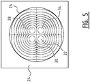
- Each lens 6a, 6b, 8a, 8b, 10a, 10b is a Fresnel lens as shown in figure 5 .
- the Fresnel lens comprises a flange 24 for fixing of the lens in casing 4.
- the lenses show the annular segments 26 typical of Fresnel lenses.
- the lenses have four optical centres 28, 30, 32, 34, each defining a different optical axis.
- the focal length is the same for all lenses.
- the projection of the detection zone of lenses 10a, 10b and the corresponding PIR sensors is depicted in figure 6 .
- the detection zone is divided into eight subzones, wherein each subzone comprises both a positive part (quadrilaterals with thin contours) and a negative part (quadrilaterals with thick contours).
- Four subzones 36a are due to lens 10a and four subzones 36b due to lens 10b.
- the upper two subzones A of subzones 36a are due to optical centres 28, 30 of lens 10a.
- the lower two subzones B of subzones 36a are due to optical centres 32, 34.Each subzone includes a negative and positive part. It is noted that the positive and negative part of the subzones are drawn spaced apart. In practice, the positive and negative parts usually adjoin each other.
- the length d1 of the projection of the total detection zone is approximately 4 m, while the width d2 is approximately 3m. Therefore, the length of each subzone, comprising one positive part and one negative part, is approximately 1 m.
- the PIR sensor has a typical bandwidth of 0.2 - 2 Hz. Therefore, this detection zone will be able to detect within a speed range of 0.2 - 2 m/s or 0.72 - 7.2 km/h. This is the speed range typical for pedestrians.
- Figure 7 shows the detection zone of lenses 8a, 8b and their corresponding PIR sensors.
- the layout is very similar to the layout shown in figure 6 , due to the use of the same lens for all three sensor pairs.
- the size of the detection zone of figure 7 is larger due to the different tilting angle of the lens and sensor: the length d3 is 10m and the width d4 is 7.5 m.
- the length of each pair of negative and positive parts is 2.5 m. Therefore, the speed range detectable by the sensors corresponding to lenses 8a, 8b is 0.5 - 5 m/s or 1.8 km /h - 18 km /h. This is the typical speed range for bicycles.
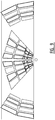
- Figure 8 shows the detection zone of lenses 6a, 6b. These lenses are orientated with their optical axes in more or less opposite directions. With respect to the detection zones of lenses 8a, 8b, 10a, 10b the lenses have been rotated about a vertical axis by an angle ⁇ of approximately 50 degrees. Furthermore the tilt of the sensor and lens have been adjusted. This results in two clusters of subzones 40a, 40b which are provided at a distance from each other. Furthermore, the lens and PIR sensor have been rotated 90 degrees about a horizontal axis perpendicular to the detection surface of the sensor, with respect to the configuration described in figures 6 and 7 . This ensures that the alternating positive and negative zones are still orientated in the desired direction with respect to the road, i.e. a vehicle passing subzones 40a and/or 40b will pass a sequence of alternating positive and negative parts.
- each of the detection zones is about 50 meters. Therefore, each pair of negative and positive part has a width of approximately 25 m.
- the detection zones of figure 8 are therefore arranged for the detection of objects having a speed in the range of 5 m/s - 50 m/s or 18 km/h - 180 km/h.
- the minimal temperature for an object to be detectable is higher than in the smaller detection zones of figures 6 and 7 . This increases the ability of the system to distinguish between cars and pedestrians / cyclists.
- Figure 9 shows an overview of all detection zones combined in one figure. Note that the pedestrian detection zone overlaps in space with the bicycle detection zone.
- the pedestrian detection zone is defined close to the pole 14, as this will be the usual place pedestrians are walking, e.g. on a sidewalk. Further note that the speed ranges of the pedestrian detection zone and bicycle detection zone overlap. In case both detectors detect an object, the system will output a signal corresponding to "bicycle", for safety reasons.
- the system indicates that an object in the speed range 1.8 - 18 km/h has been detected.
- the system is configured to output a signal indicating the speed range 0.72 - 7.2 km/h when both detectors are triggered.
- Such an alternative configuration effectively redefines the speed ranges to 0.72 - 7.2 km/h and 7.2 - 18 km/h.
- a cyclist travels along the road at a speed of 16 km/h.
- the cyclist will be detected in the detection zones 38a-b of figure 7 , as his speed falls within the speed range of 1.8 km/h - 18 km/h.
- the PIR sensor of detection zone 36 will not detect the cyclist, as it is too fast for the speed range of this detection zone. Neither will the detectors of detection zones 40a-b detect the cyclist, as the cyclist is too slow to be detected by these detectors.
- a car passing at a speed of 40 km/h will not be detected by the PIR sensors of either of the detection zones 36 and 38, as its speed is above the upper limits of the speed ranges of the corresponding motion detectors. As its speed falls within the speed range of the motion detector comprising lenses 6a, 6b, it will be detected by this motion detector.
Landscapes
- Physics & Mathematics (AREA)
- General Physics & Mathematics (AREA)
- Spectroscopy & Molecular Physics (AREA)
- Engineering & Computer Science (AREA)
- General Engineering & Computer Science (AREA)
- Traffic Control Systems (AREA)
Claims (13)
- Système de détection de mouvements (2) pour détecter des véhicules et/ou des piétons en mouvement et déterminer dans laquelle d'au moins deux plages de vitesses tombe la vitesse des véhicules et/ou des piétons détectés, comprenant :- un premier détecteur de mouvements (10a, 10b ; 8a, 8b) pour détecter des véhicules et/ou des piétons ayant une vitesse dans une première plage de vitesses, le premier détecteur étant agencé pour détecter des objets en mouvement dans une première zone de détection (36a, 36b ; 38a, 38b) ayant une première taille (d1, d2 ; d3, d4), la première taille (d1, d2 ; d3, d4) déterminant la première plage de vitesses en ce que la première taille de la première zone est choisie de façon à correspondre à la première plage de vitesses souhaitée à détecter ; et- un second détecteur de mouvements (6a, 6b) pour détecter des véhicules et/ou des piétons ayant une vitesse dans une seconde plage de vitesses, le second détecteur étant agencé pour détecter des objets en mouvement dans une seconde zone de détection (40a, 40b) ayant une seconde taille (d4, d5), la seconde taille (d4, d5) déterminant la seconde plage de vitesses en ce que la seconde taille de la seconde zone est choisie de façon à correspondre à la seconde plage de vitesses souhaitée à détecter ; et
dans lequel les deux détecteurs comprennent un capteur de mouvement infrarouge, dans lequel chaque détecteur est intrinsèquement configuré pour la détection dans une plage de vitesses donnée ; et
dans lequel le système de détection de mouvements est fixé à un éclairage urbain. - Système de détection de mouvements (2) selon la revendication 1, dans lequel au moins un des détecteurs (6a, 6b ; 8a, 8b ; 10a, 10b) comprend une lentille (6a, 6b ; 8a, 8b ; 10a, 10b) ou un miroir agencé de telle sorte que la zone de détection respective (40a, 40b ; 38a, 38b ; 36a, 36b) est divisée en au moins deux zones secondaires.
- Système de détection de mouvements (2) selon la revendication 2, dans lequel la lentille (6a, 6b ; 8a, 8b ; 10a, 10b) ou le miroir est agencé(e) de façon à diviser la zone de détection respective en quatre zones secondaires.
- Système de détection de mouvements (2) selon l'une quelconque des revendications 1 à 3, dans lequel le premier (10a, 10b ; 8a, 8b) et le second détecteur de mouvements (6a, 6b) comprennent chacun un capteur de mouvement infrarouge ayant au moins deux éléments de détection selon une configuration à polarité inversée, divisant ainsi la zone de détection respective en au moins une partie négative (figure 10A : B) et au moins une partie positive (figure 10A : A), dans lequel le second détecteur de mouvements (6a, 6b) est mis en rotation par rapport au premier détecteur de mouvements (8a, 8b ; 10a, 10b) :- autour d'un axe sensiblement vertical afin d'obtenir un emplacement différent pour la seconde zone de détection (40a, 40b) et pour la première zone de détection (36a, 36b ; 38a, 38b) ; et- autour d'un second axe pour compenser au moins partiellement la rotation de l'au moins une partie négative par rapport à l'au moins une partie positive de la seconde zone de détection (40a, 40b) comparativement à la première zone de détection (36a, 36b ; 38a, 38b) en raison de ladite rotation autour de l'axe sensiblement vertical.
- Système de détection de mouvements (2) selon l'une quelconque des revendications 1 à 4, comprenant au moins deux détecteurs de mouvements (6a, 6b ; 8a, 8b ; 10a, 10b) pour détecter des véhicules et/ou des piétons ayant une vitesse sensiblement dans la même plage de vitesses, agencé pour détecter des objets en mouvement dans les zones de détection respectives (40a, 40b ; 38a, 38b ; 36a, 36b) ayant sensiblement la même taille, ladite même taille déterminant ladite même plage de vitesses, dans lequel les zones de détection desdits au moins deux détecteurs de mouvements sont prévues à distance l'une de l'autre.
- Système de détection de mouvements (2) selon la revendication 5, comprenant en outre un composant de traitement (20) relié auxdits au moins deux détecteurs de mouvements (6a, 6b ; 8a, 8b ; 10a, 10b), adapté pour déterminer la direction d'un objet détecté sur la base de l'ordre de détection par lesdits au moins deux détecteurs de mouvements (6a, 6b ; 8a, 8b ; 10a, 10b).
- Système de détection de mouvements (2) selon l'une quelconque des revendications 1 à 6, comprenant en outre un composant de sortie pour délivrer un signal indiquant la première ou la seconde plage de vitesses, le composant de sortie étant configuré pour émettre un signal indiquant une parmi la plage de vitesses comprenant la vitesse la plus basse ou la plage de vitesses comprenant la vitesse la plus élevée lorsque le premier détecteur de mouvements et le second détecteur de mouvements détectent tous les deux un objet, de préférence la plage de vitesses comprenant la vitesse la plus élevée.
- Système de détection de mouvements (2) selon l'une quelconque des revendications 1 à 7, comprenant en outre un accéléromètre, dans lequel le système est agencé de façon à compenser la sortie du premier et du second détecteur en cas de mouvement du système (2) détecté par l'accéléromètre.
- Système d'éclairage (2, 2', 14) comprenant :- le système de détection de mouvements (2) selon l'une quelconque des revendications 1 à 8 ;- au moins une source de lumière (14) ; et- un dispositif de commande (20) qui est activement relié au système de détection de mouvements (2) et à l'au moins une source de lumière (14) pour commander l'au moins une source de lumière sur la base de la détection d'un objet en mouvement par le système de détection de mouvements.
- Système d'éclairage (2, 2', 14) selon la revendication 9, dans lequel le dispositif de commande est agencé de façon à commander l'au moins une source de lumière (14) sur la base de la plage de vitesses dans laquelle est classé l'objet détecté.
- Système d'éclairage (2, 2', 14) selon la revendication 9 ou 10, comprenant en outre un second système de détection de mouvements (2') selon l'une quelconque des revendications 1 à 9, relié au premier système de détection de mouvements (2), dans lequel le premier système de détection de mouvements (2) comprend le dispositif de commande (20), le dispositif de commande (20) étant agencé pour commander l'au moins une source de lumière (14) sur la base de la détection par les deux systèmes de détection de mouvements (2, 2').
- Système d'éclairage (2, 2', 14) selon l'une quelconque des revendications 9 à 11, comprenant un boîtier (4) comprenant une pièce de fixation pour fixer le boîtier à un réverbère (14) et une pièce amovible qui est reliée de manière amovible à la pièce de fixation, la pièce de fixation comprenant un circuit électronique pour le raccordement à la source de lumière et des moyens de raccordement électrique pour le raccordement déconnectable à une électronique supplémentaire, dans lequel le circuit électronique est configuré de manière à ce que la tension aux bornes des moyens de raccordement soit inférieure à 50 V, de préférence inférieure à 40 V, mieux encore, inférieure à 30 V.
- Procédé pour détecter des véhicules et/ou des piétons en mouvement et déterminer dans laquelle d'au moins deux plages de vitesses tombe la vitesse des véhicules et/ou des piétons détectés, comprenant :- la détection de véhicules et/ou de piétons ayant une vitesse dans une première plage de vitesses, en utilisant un premier détecteur de mouvements (10a, 10b ; 8a, 8b) agencé de façon à détecter des objets en mouvement dans une première zone de détection (36a, 36b ; 38a, 38b) ayant une première taille (d1, d2 ; d3, d4), la première taille (d1, d2 ; d3, d4) déterminant la première plage de vitesses ; et- la détection de véhicules et/ou de piétons ayant une vitesse dans une seconde plage de vitesses, en utilisant un second détecteur de mouvements (6a, 6b) agencé de façon à détecter des objets en mouvement dans une seconde zone de détection (40a, 40b) ayant une seconde taille (d4, d5), la seconde taille (d4, d5) déterminant la seconde plage de vitesses ; et
dans lequel les deux détecteurs comprennent un capteur de mouvement infrarouge, dans lequel chaque détecteur est intrinsèquement configuré pour la détection dans une plage de vitesses donnée ; et
dans lequel les deux détecteurs sont fixés à un éclairage urbain.
Applications Claiming Priority (2)
| Application Number | Priority Date | Filing Date | Title |
|---|---|---|---|
| NL2010323A NL2010323C2 (en) | 2013-02-18 | 2013-02-18 | Motion detector system, lighting system with such system and method for detecting moving vehicles and/or pedestrians. |
| PCT/NL2014/050093 WO2014126469A1 (fr) | 2013-02-18 | 2014-02-14 | Système détecteur de mouvement, système d'éclairage muni d'un tel système et procédé de détection de véhicules et/ou de piétons en mouvement |
Publications (3)
| Publication Number | Publication Date |
|---|---|
| EP2957149A1 EP2957149A1 (fr) | 2015-12-23 |
| EP2957149B1 true EP2957149B1 (fr) | 2018-04-11 |
| EP2957149B8 EP2957149B8 (fr) | 2018-07-18 |
Family
ID=48626551
Family Applications (1)
| Application Number | Title | Priority Date | Filing Date |
|---|---|---|---|
| EP14706965.2A Active EP2957149B8 (fr) | 2013-02-18 | 2014-02-14 | Système détecteur de mouvement, système d'éclairage muni d'un tel système et procédé de détection de véhicules et/ou de piétons en mouvement |
Country Status (4)
| Country | Link |
|---|---|
| US (1) | US9717131B2 (fr) |
| EP (1) | EP2957149B8 (fr) |
| NL (1) | NL2010323C2 (fr) |
| WO (1) | WO2014126469A1 (fr) |
Families Citing this family (14)
| Publication number | Priority date | Publication date | Assignee | Title |
|---|---|---|---|---|
| US9926148B2 (en) * | 2014-06-27 | 2018-03-27 | Rite-Hite Holding Corporation | Pedestrian-vehicle safety systems for loading docks |
| US9489812B2 (en) | 2014-11-17 | 2016-11-08 | Vivint, Inc. | Active infrared sensor |
| DE102014226891B4 (de) * | 2014-12-23 | 2023-08-17 | H4X E.U. | Bewegungsmelder und Leuchtensystem mit Bewegungsmelder |
| US10480996B2 (en) | 2015-01-05 | 2019-11-19 | Ideal Industries Lighting Llc | Light fixture with integrated sensor |
| US10234121B2 (en) * | 2015-01-05 | 2019-03-19 | Cree, Inc. | Flat trim ring lens for occupancy sensors |
| KR20170017401A (ko) * | 2015-08-06 | 2017-02-15 | 엘지이노텍 주식회사 | 이미지 처리 장치 |
| US10032380B2 (en) | 2016-10-05 | 2018-07-24 | Rite-Hite Holding Corporation | Pedestrian-vehicle safety systems for loading docks |
| DE102017215686A1 (de) * | 2017-09-06 | 2019-03-07 | Tridonic Gmbh & Co Kg | Bewegungssensorvorrichtung, verfahren zum betreiben einer bewegungssensorvorrichtung und beleuchtungssystem |
| JP7008195B2 (ja) * | 2017-10-27 | 2022-01-25 | パナソニックIpマネジメント株式会社 | 撮影装置 |
| US11227476B2 (en) | 2019-03-13 | 2022-01-18 | Ecolink Intelligent Technology, Inc. | Auto-configurable motion/occupancy sensor |
| US11262244B2 (en) * | 2019-06-28 | 2022-03-01 | Orange Peel Projects, Inc. | Motion detection system with dual sensor motion detectors |
| USD930490S1 (en) | 2019-06-28 | 2021-09-14 | Orange Peel Projects, Inc. | Dual sensor motion detector |
| USD939978S1 (en) | 2019-06-28 | 2022-01-04 | Orange Peel Projects, Inc. | Dual sensor motion detector |
| US11113939B1 (en) | 2020-03-06 | 2021-09-07 | Ecolink Intelligent Technology, Inc. | Person detection apparatus and method |
Family Cites Families (13)
| Publication number | Priority date | Publication date | Assignee | Title |
|---|---|---|---|---|
| KR0151302B1 (ko) * | 1995-07-13 | 1998-12-15 | 구자홍 | 위치판별 적외선센서와 이를 이용한 센싱방법 |
| US5986357A (en) | 1997-02-04 | 1999-11-16 | Mytech Corporation | Occupancy sensor and method of operating same |
| KR100530397B1 (ko) * | 1998-02-13 | 2005-11-22 | 마츠시타 덴끼 산교 가부시키가이샤 | 적외선 검출 소자, 이 적외선 검출 소자를 이용한 적외선 센서 유닛 및 적외선 검출 장치 |
| DE19910120A1 (de) * | 1999-03-08 | 2000-09-14 | Abb Patent Gmbh | Sensor zur Personendetektion |
| JP3896415B2 (ja) | 2002-07-25 | 2007-03-22 | オプテックス株式会社 | 防犯照明装置 |
| WO2009098848A1 (fr) * | 2008-02-08 | 2009-08-13 | Panasonic Corporation | Climatiseur |
| WO2010116200A1 (fr) | 2009-04-07 | 2010-10-14 | Yipi Pte Ltd | Lampe et tube à del à économie d'énergie |
| US20100265100A1 (en) | 2009-04-20 | 2010-10-21 | Lsi Industries, Inc. | Systems and methods for intelligent lighting |
| JP5302770B2 (ja) | 2009-05-20 | 2013-10-02 | パナソニック株式会社 | 照明装置 |
| GB2470926A (en) * | 2009-06-10 | 2010-12-15 | Robert Mckinley | Lighting system with sensor controlled illumination groups |
| TWI384169B (zh) | 2009-06-18 | 2013-02-01 | Utechzone Co Ltd | A full range of street light intensity control and energy saving system based on vehicle traffic and vehicle speed detection |
| KR101037093B1 (ko) | 2009-07-24 | 2011-05-26 | 이화랑 | 복합센서를 이용한 가로등 제어장치 |
| EP2636283B1 (fr) * | 2010-11-02 | 2018-08-29 | Philips Lighting Holding B.V. | Système d'éclairage à détection de radar |
-
2013
- 2013-02-18 NL NL2010323A patent/NL2010323C2/en not_active IP Right Cessation
-
2014
- 2014-02-14 EP EP14706965.2A patent/EP2957149B8/fr active Active
- 2014-02-14 US US14/768,184 patent/US9717131B2/en not_active Expired - Fee Related
- 2014-02-14 WO PCT/NL2014/050093 patent/WO2014126469A1/fr not_active Ceased
Non-Patent Citations (1)
| Title |
|---|
| None * |
Also Published As
| Publication number | Publication date |
|---|---|
| US9717131B2 (en) | 2017-07-25 |
| US20150382432A1 (en) | 2015-12-31 |
| WO2014126469A1 (fr) | 2014-08-21 |
| EP2957149A1 (fr) | 2015-12-23 |
| EP2957149B8 (fr) | 2018-07-18 |
| NL2010323C2 (en) | 2014-08-21 |
Similar Documents
| Publication | Publication Date | Title |
|---|---|---|
| EP2957149B1 (fr) | Système détecteur de mouvement, système d'éclairage muni d'un tel système et procédé de détection de véhicules et/ou de piétons en mouvement | |
| RU2427985C2 (ru) | Управляющее устройство, система и способ для общественного освещения | |
| JP6847045B2 (ja) | 車両用灯具 | |
| EP3850916B1 (fr) | Système de luminaire permettant de déterminer des informations météorologiques | |
| EP3111134B1 (fr) | Détection à base de réflexion de la lumière | |
| US20140112537A1 (en) | Systems and methods for intelligent monitoring of thoroughfares using thermal imaging | |
| JP3844737B2 (ja) | 車両の周囲を監視するための方法及び装置 | |
| JP7009987B2 (ja) | 自動運転システム及び自動運転方法 | |
| CN110997406A (zh) | 灯装置、传感器系统以及传感器装置 | |
| KR101897620B1 (ko) | 스마트 iot 조명 장치 및 시스템 | |
| GB2470926A (en) | Lighting system with sensor controlled illumination groups | |
| KR100962434B1 (ko) | 감시 카메라 | |
| KR101111724B1 (ko) | 불법 주정차 무인 검지 방법과 그 시스템 | |
| US9395248B2 (en) | Radiation sensing device and control circuit | |
| EP3095070B1 (fr) | Détection thermique | |
| KR101479178B1 (ko) | 가로등을 대체할 수 있는 cctv용 지능형 카메라장치 | |
| TWI476437B (zh) | 視覺增強系統及其裝置 | |
| WO1999004378A1 (fr) | Systeme d'imagerie video | |
| JP2005205950A (ja) | 夜間歩行者報知装置 | |
| KR101804309B1 (ko) | 위치 추적 감시 카메라 | |
| JP2006159928A (ja) | 夜間移動体報知装置及び夜間移動体報知方法 | |
| KR20130041851A (ko) | 조명 제어 시스템 | |
| KR101228824B1 (ko) | 측면 발광에 연동되어 자동으로 점등되는 주차장 조명 시스템 및 방법 | |
| KR20250032321A (ko) | 주차장 사고 예방 알림이 | |
| CZ37423U1 (cs) | Infračervený bezpečnostní systém pro zlepšení viditelnosti objektů a infračervený bezpečnostní odrazný prvek |
Legal Events
| Date | Code | Title | Description |
|---|---|---|---|
| PUAI | Public reference made under article 153(3) epc to a published international application that has entered the european phase |
Free format text: ORIGINAL CODE: 0009012 |
|
| 17P | Request for examination filed |
Effective date: 20150903 |
|
| AK | Designated contracting states |
Kind code of ref document: A1 Designated state(s): AL AT BE BG CH CY CZ DE DK EE ES FI FR GB GR HR HU IE IS IT LI LT LU LV MC MK MT NL NO PL PT RO RS SE SI SK SM TR |
|
| AX | Request for extension of the european patent |
Extension state: BA ME |
|
| DAX | Request for extension of the european patent (deleted) | ||
| STAA | Information on the status of an ep patent application or granted ep patent |
Free format text: STATUS: EXAMINATION IS IN PROGRESS |
|
| 17Q | First examination report despatched |
Effective date: 20161216 |
|
| GRAP | Despatch of communication of intention to grant a patent |
Free format text: ORIGINAL CODE: EPIDOSNIGR1 |
|
| STAA | Information on the status of an ep patent application or granted ep patent |
Free format text: STATUS: GRANT OF PATENT IS INTENDED |
|
| INTG | Intention to grant announced |
Effective date: 20170928 |
|
| GRAS | Grant fee paid |
Free format text: ORIGINAL CODE: EPIDOSNIGR3 |
|
| GRAA | (expected) grant |
Free format text: ORIGINAL CODE: 0009210 |
|
| STAA | Information on the status of an ep patent application or granted ep patent |
Free format text: STATUS: THE PATENT HAS BEEN GRANTED |
|
| AK | Designated contracting states |
Kind code of ref document: B1 Designated state(s): AL AT BE BG CH CY CZ DE DK EE ES FI FR GB GR HR HU IE IS IT LI LT LU LV MC MK MT NL NO PL PT RO RS SE SI SK SM TR |
|
| REG | Reference to a national code |
Ref country code: GB Ref legal event code: FG4D |
|
| REG | Reference to a national code |
Ref country code: CH Ref legal event code: EP Ref country code: CH Ref legal event code: NV Representative=s name: ARNOLD AND SIEDSMA AG, CH |
|
| REG | Reference to a national code |
Ref country code: AT Ref legal event code: REF Ref document number: 989353 Country of ref document: AT Kind code of ref document: T Effective date: 20180415 |
|
| RAP2 | Party data changed (patent owner data changed or rights of a patent transferred) |
Owner name: TVILIGHT B.V. |
|
| REG | Reference to a national code |
Ref country code: IE Ref legal event code: FG4D |
|
| REG | Reference to a national code |
Ref country code: DE Ref legal event code: R096 Ref document number: 602014023669 Country of ref document: DE |
|
| REG | Reference to a national code |
Ref country code: NL Ref legal event code: FP |
|
| REG | Reference to a national code |
Ref country code: LT Ref legal event code: MG4D |
|
| PG25 | Lapsed in a contracting state [announced via postgrant information from national office to epo] |
Ref country code: AL Free format text: LAPSE BECAUSE OF FAILURE TO SUBMIT A TRANSLATION OF THE DESCRIPTION OR TO PAY THE FEE WITHIN THE PRESCRIBED TIME-LIMIT Effective date: 20180411 Ref country code: ES Free format text: LAPSE BECAUSE OF FAILURE TO SUBMIT A TRANSLATION OF THE DESCRIPTION OR TO PAY THE FEE WITHIN THE PRESCRIBED TIME-LIMIT Effective date: 20180411 Ref country code: SE Free format text: LAPSE BECAUSE OF FAILURE TO SUBMIT A TRANSLATION OF THE DESCRIPTION OR TO PAY THE FEE WITHIN THE PRESCRIBED TIME-LIMIT Effective date: 20180411 Ref country code: BG Free format text: LAPSE BECAUSE OF FAILURE TO SUBMIT A TRANSLATION OF THE DESCRIPTION OR TO PAY THE FEE WITHIN THE PRESCRIBED TIME-LIMIT Effective date: 20180711 Ref country code: FI Free format text: LAPSE BECAUSE OF FAILURE TO SUBMIT A TRANSLATION OF THE DESCRIPTION OR TO PAY THE FEE WITHIN THE PRESCRIBED TIME-LIMIT Effective date: 20180411 Ref country code: NO Free format text: LAPSE BECAUSE OF FAILURE TO SUBMIT A TRANSLATION OF THE DESCRIPTION OR TO PAY THE FEE WITHIN THE PRESCRIBED TIME-LIMIT Effective date: 20180711 Ref country code: LT Free format text: LAPSE BECAUSE OF FAILURE TO SUBMIT A TRANSLATION OF THE DESCRIPTION OR TO PAY THE FEE WITHIN THE PRESCRIBED TIME-LIMIT Effective date: 20180411 Ref country code: PL Free format text: LAPSE BECAUSE OF FAILURE TO SUBMIT A TRANSLATION OF THE DESCRIPTION OR TO PAY THE FEE WITHIN THE PRESCRIBED TIME-LIMIT Effective date: 20180411 |
|
| PG25 | Lapsed in a contracting state [announced via postgrant information from national office to epo] |
Ref country code: GR Free format text: LAPSE BECAUSE OF FAILURE TO SUBMIT A TRANSLATION OF THE DESCRIPTION OR TO PAY THE FEE WITHIN THE PRESCRIBED TIME-LIMIT Effective date: 20180712 Ref country code: HR Free format text: LAPSE BECAUSE OF FAILURE TO SUBMIT A TRANSLATION OF THE DESCRIPTION OR TO PAY THE FEE WITHIN THE PRESCRIBED TIME-LIMIT Effective date: 20180411 Ref country code: LV Free format text: LAPSE BECAUSE OF FAILURE TO SUBMIT A TRANSLATION OF THE DESCRIPTION OR TO PAY THE FEE WITHIN THE PRESCRIBED TIME-LIMIT Effective date: 20180411 Ref country code: RS Free format text: LAPSE BECAUSE OF FAILURE TO SUBMIT A TRANSLATION OF THE DESCRIPTION OR TO PAY THE FEE WITHIN THE PRESCRIBED TIME-LIMIT Effective date: 20180411 |
|
| REG | Reference to a national code |
Ref country code: AT Ref legal event code: MK05 Ref document number: 989353 Country of ref document: AT Kind code of ref document: T Effective date: 20180411 |
|
| PG25 | Lapsed in a contracting state [announced via postgrant information from national office to epo] |
Ref country code: PT Free format text: LAPSE BECAUSE OF FAILURE TO SUBMIT A TRANSLATION OF THE DESCRIPTION OR TO PAY THE FEE WITHIN THE PRESCRIBED TIME-LIMIT Effective date: 20180813 |
|
| REG | Reference to a national code |
Ref country code: DE Ref legal event code: R097 Ref document number: 602014023669 Country of ref document: DE |
|
| PG25 | Lapsed in a contracting state [announced via postgrant information from national office to epo] |
Ref country code: RO Free format text: LAPSE BECAUSE OF FAILURE TO SUBMIT A TRANSLATION OF THE DESCRIPTION OR TO PAY THE FEE WITHIN THE PRESCRIBED TIME-LIMIT Effective date: 20180411 Ref country code: CZ Free format text: LAPSE BECAUSE OF FAILURE TO SUBMIT A TRANSLATION OF THE DESCRIPTION OR TO PAY THE FEE WITHIN THE PRESCRIBED TIME-LIMIT Effective date: 20180411 Ref country code: DK Free format text: LAPSE BECAUSE OF FAILURE TO SUBMIT A TRANSLATION OF THE DESCRIPTION OR TO PAY THE FEE WITHIN THE PRESCRIBED TIME-LIMIT Effective date: 20180411 Ref country code: AT Free format text: LAPSE BECAUSE OF FAILURE TO SUBMIT A TRANSLATION OF THE DESCRIPTION OR TO PAY THE FEE WITHIN THE PRESCRIBED TIME-LIMIT Effective date: 20180411 Ref country code: EE Free format text: LAPSE BECAUSE OF FAILURE TO SUBMIT A TRANSLATION OF THE DESCRIPTION OR TO PAY THE FEE WITHIN THE PRESCRIBED TIME-LIMIT Effective date: 20180411 Ref country code: SK Free format text: LAPSE BECAUSE OF FAILURE TO SUBMIT A TRANSLATION OF THE DESCRIPTION OR TO PAY THE FEE WITHIN THE PRESCRIBED TIME-LIMIT Effective date: 20180411 |
|
| PLBE | No opposition filed within time limit |
Free format text: ORIGINAL CODE: 0009261 |
|
| STAA | Information on the status of an ep patent application or granted ep patent |
Free format text: STATUS: NO OPPOSITION FILED WITHIN TIME LIMIT |
|
| PG25 | Lapsed in a contracting state [announced via postgrant information from national office to epo] |
Ref country code: IT Free format text: LAPSE BECAUSE OF FAILURE TO SUBMIT A TRANSLATION OF THE DESCRIPTION OR TO PAY THE FEE WITHIN THE PRESCRIBED TIME-LIMIT Effective date: 20180411 Ref country code: SM Free format text: LAPSE BECAUSE OF FAILURE TO SUBMIT A TRANSLATION OF THE DESCRIPTION OR TO PAY THE FEE WITHIN THE PRESCRIBED TIME-LIMIT Effective date: 20180411 |
|
| 26N | No opposition filed |
Effective date: 20190114 |
|
| PGFP | Annual fee paid to national office [announced via postgrant information from national office to epo] |
Ref country code: CH Payment date: 20190226 Year of fee payment: 6 Ref country code: GB Payment date: 20190226 Year of fee payment: 6 Ref country code: DE Payment date: 20190227 Year of fee payment: 6 |
|
| PG25 | Lapsed in a contracting state [announced via postgrant information from national office to epo] |
Ref country code: SI Free format text: LAPSE BECAUSE OF FAILURE TO SUBMIT A TRANSLATION OF THE DESCRIPTION OR TO PAY THE FEE WITHIN THE PRESCRIBED TIME-LIMIT Effective date: 20180411 |
|
| PGFP | Annual fee paid to national office [announced via postgrant information from national office to epo] |
Ref country code: FR Payment date: 20190227 Year of fee payment: 6 |
|
| PG25 | Lapsed in a contracting state [announced via postgrant information from national office to epo] |
Ref country code: MC Free format text: LAPSE BECAUSE OF FAILURE TO SUBMIT A TRANSLATION OF THE DESCRIPTION OR TO PAY THE FEE WITHIN THE PRESCRIBED TIME-LIMIT Effective date: 20180411 Ref country code: LU Free format text: LAPSE BECAUSE OF NON-PAYMENT OF DUE FEES Effective date: 20190214 |
|
| REG | Reference to a national code |
Ref country code: BE Ref legal event code: MM Effective date: 20190228 |
|
| REG | Reference to a national code |
Ref country code: IE Ref legal event code: MM4A |
|
| PG25 | Lapsed in a contracting state [announced via postgrant information from national office to epo] |
Ref country code: IE Free format text: LAPSE BECAUSE OF NON-PAYMENT OF DUE FEES Effective date: 20190214 |
|
| PG25 | Lapsed in a contracting state [announced via postgrant information from national office to epo] |
Ref country code: BE Free format text: LAPSE BECAUSE OF NON-PAYMENT OF DUE FEES Effective date: 20190228 |
|
| PG25 | Lapsed in a contracting state [announced via postgrant information from national office to epo] |
Ref country code: TR Free format text: LAPSE BECAUSE OF FAILURE TO SUBMIT A TRANSLATION OF THE DESCRIPTION OR TO PAY THE FEE WITHIN THE PRESCRIBED TIME-LIMIT Effective date: 20180411 |
|
| PG25 | Lapsed in a contracting state [announced via postgrant information from national office to epo] |
Ref country code: MT Free format text: LAPSE BECAUSE OF NON-PAYMENT OF DUE FEES Effective date: 20190214 |
|
| REG | Reference to a national code |
Ref country code: DE Ref legal event code: R119 Ref document number: 602014023669 Country of ref document: DE |
|
| REG | Reference to a national code |
Ref country code: CH Ref legal event code: PL |
|
| GBPC | Gb: european patent ceased through non-payment of renewal fee |
Effective date: 20200214 |
|
| PG25 | Lapsed in a contracting state [announced via postgrant information from national office to epo] |
Ref country code: CH Free format text: LAPSE BECAUSE OF NON-PAYMENT OF DUE FEES Effective date: 20200229 Ref country code: LI Free format text: LAPSE BECAUSE OF NON-PAYMENT OF DUE FEES Effective date: 20200229 |
|
| PG25 | Lapsed in a contracting state [announced via postgrant information from national office to epo] |
Ref country code: DE Free format text: LAPSE BECAUSE OF NON-PAYMENT OF DUE FEES Effective date: 20200901 Ref country code: FR Free format text: LAPSE BECAUSE OF NON-PAYMENT OF DUE FEES Effective date: 20200229 Ref country code: GB Free format text: LAPSE BECAUSE OF NON-PAYMENT OF DUE FEES Effective date: 20200214 |
|
| PG25 | Lapsed in a contracting state [announced via postgrant information from national office to epo] |
Ref country code: CY Free format text: LAPSE BECAUSE OF FAILURE TO SUBMIT A TRANSLATION OF THE DESCRIPTION OR TO PAY THE FEE WITHIN THE PRESCRIBED TIME-LIMIT Effective date: 20180411 |
|
| PG25 | Lapsed in a contracting state [announced via postgrant information from national office to epo] |
Ref country code: IS Free format text: LAPSE BECAUSE OF FAILURE TO SUBMIT A TRANSLATION OF THE DESCRIPTION OR TO PAY THE FEE WITHIN THE PRESCRIBED TIME-LIMIT Effective date: 20180811 |
|
| PG25 | Lapsed in a contracting state [announced via postgrant information from national office to epo] |
Ref country code: HU Free format text: LAPSE BECAUSE OF FAILURE TO SUBMIT A TRANSLATION OF THE DESCRIPTION OR TO PAY THE FEE WITHIN THE PRESCRIBED TIME-LIMIT; INVALID AB INITIO Effective date: 20140214 |
|
| PG25 | Lapsed in a contracting state [announced via postgrant information from national office to epo] |
Ref country code: MK Free format text: LAPSE BECAUSE OF FAILURE TO SUBMIT A TRANSLATION OF THE DESCRIPTION OR TO PAY THE FEE WITHIN THE PRESCRIBED TIME-LIMIT Effective date: 20180411 |
|
| P01 | Opt-out of the competence of the unified patent court (upc) registered |
Effective date: 20230516 |
|
| PGFP | Annual fee paid to national office [announced via postgrant information from national office to epo] |
Ref country code: NL Payment date: 20260226 Year of fee payment: 13 |