EP2957376A2 - Verfahren zum Herstellen eines verbundenen Artikels unter Verwendung einer poröse Zwischenschichtsregion - Google Patents
Verfahren zum Herstellen eines verbundenen Artikels unter Verwendung einer poröse Zwischenschichtsregion Download PDFInfo
- Publication number
- EP2957376A2 EP2957376A2 EP15158479.4A EP15158479A EP2957376A2 EP 2957376 A2 EP2957376 A2 EP 2957376A2 EP 15158479 A EP15158479 A EP 15158479A EP 2957376 A2 EP2957376 A2 EP 2957376A2
- Authority
- EP
- European Patent Office
- Prior art keywords
- articles
- interlayer
- interlayer region
- porous
- article
- Prior art date
- Legal status (The legal status is an assumption and is not a legal conclusion. Google has not performed a legal analysis and makes no representation as to the accuracy of the status listed.)
- Granted
Links
Images


Classifications
-
- B—PERFORMING OPERATIONS; TRANSPORTING
- B22—CASTING; POWDER METALLURGY
- B22F—WORKING METALLIC POWDER; MANUFACTURE OF ARTICLES FROM METALLIC POWDER; MAKING METALLIC POWDER; APPARATUS OR DEVICES SPECIALLY ADAPTED FOR METALLIC POWDER
- B22F7/00—Manufacture of composite layers, workpieces, or articles, comprising metallic powder, by sintering the powder, with or without compacting wherein at least one part is obtained by sintering or compression
- B22F7/002—Manufacture of composite layers, workpieces, or articles, comprising metallic powder, by sintering the powder, with or without compacting wherein at least one part is obtained by sintering or compression of porous nature
- B22F7/004—Manufacture of composite layers, workpieces, or articles, comprising metallic powder, by sintering the powder, with or without compacting wherein at least one part is obtained by sintering or compression of porous nature comprising at least one non-porous part
-
- B—PERFORMING OPERATIONS; TRANSPORTING
- B22—CASTING; POWDER METALLURGY
- B22F—WORKING METALLIC POWDER; MANUFACTURE OF ARTICLES FROM METALLIC POWDER; MAKING METALLIC POWDER; APPARATUS OR DEVICES SPECIALLY ADAPTED FOR METALLIC POWDER
- B22F10/00—Additive manufacturing of workpieces or articles from metallic powder
- B22F10/20—Direct sintering or melting
- B22F10/25—Direct deposition of metal particles, e.g. direct metal deposition [DMD] or laser engineered net shaping [LENS]
-
- B—PERFORMING OPERATIONS; TRANSPORTING
- B22—CASTING; POWDER METALLURGY
- B22F—WORKING METALLIC POWDER; MANUFACTURE OF ARTICLES FROM METALLIC POWDER; MAKING METALLIC POWDER; APPARATUS OR DEVICES SPECIALLY ADAPTED FOR METALLIC POWDER
- B22F10/00—Additive manufacturing of workpieces or articles from metallic powder
- B22F10/20—Direct sintering or melting
- B22F10/28—Powder bed fusion, e.g. selective laser melting [SLM] or electron beam melting [EBM]
-
- B—PERFORMING OPERATIONS; TRANSPORTING
- B23—MACHINE TOOLS; METAL-WORKING NOT OTHERWISE PROVIDED FOR
- B23K—SOLDERING OR UNSOLDERING; WELDING; CLADDING OR PLATING BY SOLDERING OR WELDING; CUTTING BY APPLYING HEAT LOCALLY, e.g. FLAME CUTTING; WORKING BY LASER BEAM
- B23K11/00—Resistance welding; Severing by resistance heating
- B23K11/02—Pressure butt welding
-
- B—PERFORMING OPERATIONS; TRANSPORTING
- B23—MACHINE TOOLS; METAL-WORKING NOT OTHERWISE PROVIDED FOR
- B23K—SOLDERING OR UNSOLDERING; WELDING; CLADDING OR PLATING BY SOLDERING OR WELDING; CUTTING BY APPLYING HEAT LOCALLY, e.g. FLAME CUTTING; WORKING BY LASER BEAM
- B23K11/00—Resistance welding; Severing by resistance heating
- B23K11/16—Resistance welding; Severing by resistance heating taking account of the properties of the material to be welded
- B23K11/18—Resistance welding; Severing by resistance heating taking account of the properties of the material to be welded of non-ferrous metals
-
- B—PERFORMING OPERATIONS; TRANSPORTING
- B23—MACHINE TOOLS; METAL-WORKING NOT OTHERWISE PROVIDED FOR
- B23K—SOLDERING OR UNSOLDERING; WELDING; CLADDING OR PLATING BY SOLDERING OR WELDING; CUTTING BY APPLYING HEAT LOCALLY, e.g. FLAME CUTTING; WORKING BY LASER BEAM
- B23K20/00—Non-electric welding by applying impact or other pressure, with or without the application of heat, e.g. cladding or plating
- B23K20/02—Non-electric welding by applying impact or other pressure, with or without the application of heat, e.g. cladding or plating by means of a press ; Diffusion bonding
- B23K20/023—Thermo-compression bonding
-
- B—PERFORMING OPERATIONS; TRANSPORTING
- B23—MACHINE TOOLS; METAL-WORKING NOT OTHERWISE PROVIDED FOR
- B23K—SOLDERING OR UNSOLDERING; WELDING; CLADDING OR PLATING BY SOLDERING OR WELDING; CUTTING BY APPLYING HEAT LOCALLY, e.g. FLAME CUTTING; WORKING BY LASER BEAM
- B23K20/00—Non-electric welding by applying impact or other pressure, with or without the application of heat, e.g. cladding or plating
- B23K20/02—Non-electric welding by applying impact or other pressure, with or without the application of heat, e.g. cladding or plating by means of a press ; Diffusion bonding
- B23K20/023—Thermo-compression bonding
- B23K20/026—Thermo-compression bonding with diffusion of soldering material
-
- B—PERFORMING OPERATIONS; TRANSPORTING
- B23—MACHINE TOOLS; METAL-WORKING NOT OTHERWISE PROVIDED FOR
- B23K—SOLDERING OR UNSOLDERING; WELDING; CLADDING OR PLATING BY SOLDERING OR WELDING; CUTTING BY APPLYING HEAT LOCALLY, e.g. FLAME CUTTING; WORKING BY LASER BEAM
- B23K20/00—Non-electric welding by applying impact or other pressure, with or without the application of heat, e.g. cladding or plating
- B23K20/16—Non-electric welding by applying impact or other pressure, with or without the application of heat, e.g. cladding or plating with interposition of special material to facilitate connection of the parts, e.g. material for absorbing or producing gas
-
- B—PERFORMING OPERATIONS; TRANSPORTING
- B23—MACHINE TOOLS; METAL-WORKING NOT OTHERWISE PROVIDED FOR
- B23K—SOLDERING OR UNSOLDERING; WELDING; CLADDING OR PLATING BY SOLDERING OR WELDING; CUTTING BY APPLYING HEAT LOCALLY, e.g. FLAME CUTTING; WORKING BY LASER BEAM
- B23K20/00—Non-electric welding by applying impact or other pressure, with or without the application of heat, e.g. cladding or plating
- B23K20/22—Non-electric welding by applying impact or other pressure, with or without the application of heat, e.g. cladding or plating taking account of the properties of the materials to be welded
- B23K20/233—Non-electric welding by applying impact or other pressure, with or without the application of heat, e.g. cladding or plating taking account of the properties of the materials to be welded without ferrous layer
-
- B—PERFORMING OPERATIONS; TRANSPORTING
- B23—MACHINE TOOLS; METAL-WORKING NOT OTHERWISE PROVIDED FOR
- B23K—SOLDERING OR UNSOLDERING; WELDING; CLADDING OR PLATING BY SOLDERING OR WELDING; CUTTING BY APPLYING HEAT LOCALLY, e.g. FLAME CUTTING; WORKING BY LASER BEAM
- B23K20/00—Non-electric welding by applying impact or other pressure, with or without the application of heat, e.g. cladding or plating
- B23K20/24—Preliminary treatment
-
- B—PERFORMING OPERATIONS; TRANSPORTING
- B23—MACHINE TOOLS; METAL-WORKING NOT OTHERWISE PROVIDED FOR
- B23K—SOLDERING OR UNSOLDERING; WELDING; CLADDING OR PLATING BY SOLDERING OR WELDING; CUTTING BY APPLYING HEAT LOCALLY, e.g. FLAME CUTTING; WORKING BY LASER BEAM
- B23K26/00—Working by laser beam, e.g. welding, cutting or boring
- B23K26/34—Laser welding for purposes other than joining
-
- B—PERFORMING OPERATIONS; TRANSPORTING
- B33—ADDITIVE MANUFACTURING TECHNOLOGY
- B33Y—ADDITIVE MANUFACTURING, i.e. MANUFACTURING OF THREE-DIMENSIONAL [3D] OBJECTS BY ADDITIVE DEPOSITION, ADDITIVE AGGLOMERATION OR ADDITIVE LAYERING, e.g. BY 3D PRINTING, STEREOLITHOGRAPHY OR SELECTIVE LASER SINTERING
- B33Y10/00—Processes of additive manufacturing
-
- B—PERFORMING OPERATIONS; TRANSPORTING
- B22—CASTING; POWDER METALLURGY
- B22F—WORKING METALLIC POWDER; MANUFACTURE OF ARTICLES FROM METALLIC POWDER; MAKING METALLIC POWDER; APPARATUS OR DEVICES SPECIALLY ADAPTED FOR METALLIC POWDER
- B22F10/00—Additive manufacturing of workpieces or articles from metallic powder
- B22F10/30—Process control
- B22F10/32—Process control of the atmosphere, e.g. composition or pressure in a building chamber
-
- B—PERFORMING OPERATIONS; TRANSPORTING
- B22—CASTING; POWDER METALLURGY
- B22F—WORKING METALLIC POWDER; MANUFACTURE OF ARTICLES FROM METALLIC POWDER; MAKING METALLIC POWDER; APPARATUS OR DEVICES SPECIALLY ADAPTED FOR METALLIC POWDER
- B22F2998/00—Supplementary information concerning processes or compositions relating to powder metallurgy
- B22F2998/10—Processes characterised by the sequence of their steps
-
- B—PERFORMING OPERATIONS; TRANSPORTING
- B22—CASTING; POWDER METALLURGY
- B22F—WORKING METALLIC POWDER; MANUFACTURE OF ARTICLES FROM METALLIC POWDER; MAKING METALLIC POWDER; APPARATUS OR DEVICES SPECIALLY ADAPTED FOR METALLIC POWDER
- B22F3/00—Manufacture of workpieces or articles from metallic powder characterised by the manner of compacting or sintering; Apparatus specially adapted therefor ; Presses and furnaces
- B22F3/10—Sintering only
- B22F3/11—Making porous workpieces or articles
- B22F3/1146—After-treatment maintaining the porosity
-
- B—PERFORMING OPERATIONS; TRANSPORTING
- B23—MACHINE TOOLS; METAL-WORKING NOT OTHERWISE PROVIDED FOR
- B23K—SOLDERING OR UNSOLDERING; WELDING; CLADDING OR PLATING BY SOLDERING OR WELDING; CUTTING BY APPLYING HEAT LOCALLY, e.g. FLAME CUTTING; WORKING BY LASER BEAM
- B23K2101/00—Articles made by soldering, welding or cutting
- B23K2101/001—Turbines
-
- B—PERFORMING OPERATIONS; TRANSPORTING
- B23—MACHINE TOOLS; METAL-WORKING NOT OTHERWISE PROVIDED FOR
- B23K—SOLDERING OR UNSOLDERING; WELDING; CLADDING OR PLATING BY SOLDERING OR WELDING; CUTTING BY APPLYING HEAT LOCALLY, e.g. FLAME CUTTING; WORKING BY LASER BEAM
- B23K2103/00—Materials to be soldered, welded or cut
- B23K2103/08—Non-ferrous metals or alloys
- B23K2103/14—Titanium or alloys thereof
-
- B—PERFORMING OPERATIONS; TRANSPORTING
- B23—MACHINE TOOLS; METAL-WORKING NOT OTHERWISE PROVIDED FOR
- B23P—METAL-WORKING NOT OTHERWISE PROVIDED FOR; COMBINED OPERATIONS; UNIVERSAL MACHINE TOOLS
- B23P6/00—Restoring or reconditioning objects
- B23P6/002—Repairing turbine components, e.g. moving or stationary blades, rotors
- B23P6/005—Repairing turbine components, e.g. moving or stationary blades, rotors using only replacement pieces of a particular form
-
- Y—GENERAL TAGGING OF NEW TECHNOLOGICAL DEVELOPMENTS; GENERAL TAGGING OF CROSS-SECTIONAL TECHNOLOGIES SPANNING OVER SEVERAL SECTIONS OF THE IPC; TECHNICAL SUBJECTS COVERED BY FORMER USPC CROSS-REFERENCE ART COLLECTIONS [XRACs] AND DIGESTS
- Y02—TECHNOLOGIES OR APPLICATIONS FOR MITIGATION OR ADAPTATION AGAINST CLIMATE CHANGE
- Y02P—CLIMATE CHANGE MITIGATION TECHNOLOGIES IN THE PRODUCTION OR PROCESSING OF GOODS
- Y02P10/00—Technologies related to metal processing
- Y02P10/25—Process efficiency
Definitions
- the present invention relates to a method of bonding articles, and particularly to a method of bonding articles by a solid state bonding process.
- Diffusion bonding is a solid state welding technique, in which heat and high pressure is applied to the components to be bonded in a direction normal to the bond interface at high temperatures, such that atoms of respective bonding surfaces of the articles intermingle over time to form a bonded article.
- an interlayer is provided between the first and second articles in order to provide improved alignment between the first and second articles.
- a powder metal interlayer is interposed between the respective bonding surfaces.
- an interlayer in the form of a preform metal powder ring is interposed between the bonding surfaces and subsequently heated and pressed by the other article to form a consolidated interlayer bonded to the respective bonding surfaces of the articles.
- the powdered metal interlayer may be partially consolidated and formed via conventional rolling or cold compression, before being placed between the articles and subjected to heat and pressure to diffusion bond the articles together.
- the present invention describes a bonding method which seeks to overcome some or all of the above problems.
- a method of forming a bonded article comprising:
- the invention provides a method of bonding first and second articles which has been found to result in an improved strength bond.
- the porosity of the interlayer region provides improved mechanical interlocking between the first and second articles during the bonding step, thereby maintaining the relative positions of the first and second articles.
- the method also provides improved bonding strength between the first and second articles.
- the porous interlayer region provides a source of vacancy rich material for assisting grain growth from parent grains from the bonding surfaces of the first and second articles into the interlayer, being most favourable for grains which are not optimally aligned thus promoting accelerated diffusion driven grain growth across the interface.
- the porous interlayer region may comprise closed pores, such that the porous interlayer region comprises a plurality of closed cells.
- the porous interlayer region may comprise open pores, such that the porous interlayer comprises a plurality of interconnected cells.
- the material from the adjacent first or second article has been found to plastically flow around the ligaments joining the cells, thereby improving bonding between the layers.
- the cells of the porous interlayer region may comprise cells generally having an aspect ratio of less than 3:1. It has been discovered by the inventors that cells having a high aspect ratio collapse more readily than cells having a low aspect ratio, and this permits bonding to occur between the articles at lower pressure, as well as preventing voids remaining in the bonded article.
- the cells may have an average diameter of between 0.15 and 1 mm.
- the cells may have an average diameter of between approximately 0.3mm and 1 mm, and in one example, the cells may have an average length of 0.64mm, and may have an average width and or thickness of 0.35mm.
- the interlayer region may have a thickness of between 0.05 and 1 mm.
- the interlayer region is sufficiently thick to act as a buffer layer between the faying surfaces of the first and second articles, without being excessively thick so as to introduce imprecision and require excessive upset of the first and second articles to achieve full consolidation of the interlayer region which would otherwise result in excessive loss of material of the first and second articles.
- the porous interlayer region may comprise a lip comprising an edge region having a greater thickness than a central region.
- the porous interlayer region may be dimensioned such that the lip extends either side of the first and second layers, such that the lip is not located between the first and second articles.
- the lip contains extrusion from the bonding region during upset, and may also assist with fitting the remainder of the porous interlayer region in between the first and second articles.
- the interlayer region may have a surface roughness parameter on at least one faying surface of greater than 25 Ra due to the pores of the interlayer region. It has been found by the inventors that a surface roughness greater than 25 Ra aids mechanical interlocking with the faying surfaces and enhances plastic collapse of the interlayer region.
- the step of providing a porous interlayer region interposed between the bonding surfaces of the first and second articles may comprise providing an additive coating on the respective bonding surface of one or both of the first and second articles.
- the step of providing an additive coating may comprise an additive manufacturing method such as one or more of cold spraying, laser assisted cold spraying, blown powder laser deposition and vacuum plasma spraying.
- the porous interlayer region is provided directly on one or both of the first and second articles, thereby reducing part count, and ensuring accurate alignment of the interlayer region and at least one of the first and second articles.
- the use of an additive layer manufacturing method enables the porous interlayer region to have the desired porosity and pore size, shape and distribution. Additive manufacturing methods have the further advantage of being relatively quick and inexpensive, while reducing part count.
- the step of providing a porous interlayer region interposed between the bonding surfaces of the first and second articles may comprise selectively removing surface material.
- the step of selectively removing surface material may comprise removing material by a power beam material processing method such as any of volatilisation, ablation and etching.
- the step of providing a porous interlayer region interposed between the bonding surfaces of the first and second articles may comprise providing a power beam such as a laser or an electron beam, and moving the focus of the beam on a surface of one of the first and second articles to move material of the respective article.
- a power beam such as a laser or an electron beam
- the step of forming a desired surface profile on one or more surfaces of the porous interlayer region may comprise removing surface material by a power beam material processing method such as any of volatilisation, ablation and etching.
- the step of providing a porous interlayer region between the bonding surfaces of the first and second articles may comprise forming a porous preform article, and interposing the porous preform article between the bonding surfaces of the first and second articles.
- the step of forming the porous preform article may comprise an additive manufacturing process such as any of cold spraying, laser assisted cold spraying, blown powder laser deposition and vacuum plasma spraying.
- the step of forming the porous preform article may comprise a powder metallurgy process such as cold isostatic pressuring (CIP), hot isostatic pressing (HIP) or sintering, or a combination of these processes.
- CIP cold isostatic pressuring
- HIP hot isostatic pressing
- sintering or a combination of these processes.
- the step of forming the porous interlayer region may be carried out in a controlled low oxygen/interstitial environment.
- the step of forming the porous interlayer may be carried out in an inert gas environment having less than 10 parts per million (ppm) of oxygen and less than approximately 5 ppm moisture and a dew point of less than -65°C.
- the step of forming the porous preform may be carried out in a vacuum having a pressure of less than 10 -4 Torr (130 Pascals). This is particularly advantageous where the porous interlayer comprises closed cells, as gas remaining within the closed cells may otherwise prevent full consolidation of the porous interlayer region.
- the step of providing a porous interlayer region interposed between the bond surfaces of the first and second articles may comprise aligning the crystallographic orientation of the porous interlayer region with the crystallographic orientation of one or both of the first and second articles.
- the bond strength can be improved by matching the crystallographic orientation of the porous interlayer with that of the first and / or second articles.
- the step of locally heating the interlayer region may comprise electrical resistance heating of the interlayer by passing an electrical current through the interlayer.
- electrical resistance heating the porous structure concentrates the current density in the interlayer, and therefore heating along the joint line, minimising thermal disruption to the surrounding parent material in the first and second articles.
- the porous interlayer also provides more even heating compared to prior interlayers, resulting in an improved bond due to the absence of hot spots.
- the porous interlayer region may comprise the same material as the bonding surfaces of the first and second articles.
- the bonding surfaces first and second articles may comprise titanium or titanium alloy such as Ti6V4Al alloy, and the porous interlayer region may comprise titanium or titanium alloy.
- at least one of the first and second articles and the porous interlayer may comprise an intermetallic compound such as gamma titanium aluminide.
- the bonded articles may comprise a gas turbine engine component.
- the method may be utilised to fabricate or repair a gas turbine engine component such as a variable inlet guide vane (VIGV) actuator lug, casing boss, Blisk aerofoil and blisk circumferential joints.
- a gas turbine engine component such as a variable inlet guide vane (VIGV) actuator lug, casing boss, Blisk aerofoil and blisk circumferential joints.
- VGV variable inlet guide vane
- the method may be utilised to replace a stage of a blisk drum.
- a bonded article comprising first and second articles and a porous interlayer region bonded together in accordance with the first aspect of the invention.
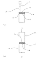
- Figure 1 shows a first step of a first bonding method.
- the method comprises providing a first article in the form of a blisk 12 having a bonding surface 14, and applying a porous interlayer region 16 on the surface 14 by an additive manufacturing process, then diffusion bonding the first article 12 and porous interlayer 16 to a second article 26.
- At least the bonding surface 14 of the blisk 12 comprises a titanium alloy such as Ti6V4Al alloy having a metallurgically clean surface 14.
- one or both of the articles 12, 14, and also perhaps the interlayer 16 could comprise an intermetallic compound such as gamma titanium aluminide ( ⁇ TiAl).
- ⁇ TiAl gamma titanium aluminide
- the metallurgically clean surface may be provided by a suitable material removal process such as chemical etching, laser cleaning or solvent cleaning.
- the additive manufacturing process comprises cold spraying, also known as cold gas dynamic spraying.
- cold spraying also known as cold gas dynamic spraying.
- relatively small metal particles 18 ranging in size from approximately 5 ⁇ m to 150 ⁇ m in diameter, or in some cases from 15 ⁇ m to 50 ⁇ m in diameter
- a nozzle such as a de Leval nozzle 20 to a critical high velocity (typically 300-1400m/s), and subsequently plastically deform (or melt) and develop a deposit on the bonding surface 14.
- the nozzle 20 is rastered backward and forward across the surface 14 to build the required structure having the required porosity, pore size and dimensions.
- cold spraying does not involve melting the metal powder, elemental segregation of the metal powder is avoided.
- Cold spraying has also been found to provide good bonding integrity between the interlayer 16 and the bonding surface 14. Furthermore, cold spraying has been found to increase the crystallographic disruption (dislocation density), which speeds diffusion by providing additional pathways and entropy to be reduced by stabilising grain shapes.
- the additive manufacture process can be used to provide a desired textured surface for the porous interlayer 16.
- the desired textured surface comprises a series of protrusions and cavities, such that the porous interlayer 16 has a surface roughness parameter of approximately 25 Ra (where Ra is the arithmetic average of the roughness profile).
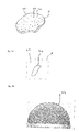
- Fig. 3a shows the porous interlayer 16 in more detail.
- the porous interlayer 16 has a thickness of typically 50-500 ⁇ m and the upper surface 22 has a shape roughly equal to that of the bonding surface 14.
- the porous interlayer region 16 comprises a plurality of either closed or open pores (or a mixture of the two) in the form of cells 24 distributed evenly throughout the interlayer 16. Where the cells 24 are closed, or the additive manufacturing process comprises one involving a molten material (such as electron beam melting (EBM)), the additive manufacturing process must be carried out in a low pressure, low oxygen environment to allow consolidation in the bonding step, as described below.
- EBM electron beam melting
- the porous interlayer 16 has a porosity of approximately 10% to 30%, that is to say the internal volume defined by the pores comprises 10% to 30% of the total volume of the interlayer 16.
- the porous interlayer 16 has a density of approximately 70% to 90% of the fully consolidated density of the material of the interlayer (i.e. Ti6Al4V in the described embodiment).
- Fig. 3b shows a close up view of one of area A of Fig. 3a , showing one of the cells 24.
- the cells 24 have an average diameter at their longest point of between about 0.3mm and 1 mm and have an aspect ratio (i.e. the ratio between the length at the longest point and the width at the shortest point) of less than about 3:1.
- the pores have a length at their longest point of approximately 0.64 mm, and a width of approximately 0.35 mm. This ensures collapse of the pores during the bonding step, thereby preventing the formation of voids in the bonded article, and reducing the pressure required for the bonding step.
- the first article 12 is bonded to a second article 26 along respective bonding surfaces 14, 28 in a second step.
- the second article comprises a component 26.
- the component 26 could comprise a component of a gas turbine engine (not shown) such as a variable inlet guide vane (VIGV) actuator lug, casing boss, blisk aerofoil or blisk circumferential joint.
- the component 26 comprises a metal such as titanium alloy, and has a metallurgically clean bonding surface 28.
- the third step is illustrated in Fig. 2
- the second article 26 is placed on top of the upper surface 22 of the interlayer region 16 such that the respective bonding surfaces 14, 28 of the first and second articles 12, 26 lie approximately parallel to one another, with the porous interlayer region 16 interposed between the respective bonding surfaces 14, 28.
- the first and second articles 12, 26 and interlayer region 16 are then bonded together in a pressure assisted bonding step.
- the porous interlayer region 16 is locally heated until a desired temperature is reached.
- Axial pressure is simultaneously applied normal to the interface between the first and second articles 12, 26 to bond the first 12 and second 26 articles together. Fixtures may be employed to hold the articles 12, 26 together during the second step.
- the resultant bonding is thought to be a result of a combination of creep (i.e. plastic flow) of the materials of the bonding surfaces of the first and second articles 12, 26 in to the cells formed in the interlayer region 16, and diffusion bonding of the interlayer region 16 with the bonding surfaces of the first and second articles 12, 26.
- the porous interlayer region 16 is locally heated by electrical resistance heating, in which an electrical current is passed through the porous interlayer region 16.
- the current could be AC, DC, or pulsed DC.
- the root mean squared (RMS) power may be approximately 850 watts
- the RMS voltage may be approximate 2 volts
- the RMS current may be approximately 360 amps
- the resistance may be 1 to 2 milli-ohms.
- the porous structure of the interlayer region 16 concentrates current density and therefore heating along the joint line, minimising thermal disruption to the surrounding parent material, thereby preventing or reducing the extent of a heat affected zone in the bonded article.
- the pores provide additional paths for the electrical current to flow, thereby reducing arcing between peaks in the surfaces of the articles 12, 26 and interlayer region 16.
- the desired temperature achieved during heating is a temperature below the melting point of the materials of the first and second articles 12, 26 and interlayer region 16, but sufficiently high to allow plastic deformation and diffusion bonding to occur at the axial pressure used.
- the temperature in the porous interlayer is raised to approximately 900 - 1000°C, and maintained for approximately 15 to 45 minutes.
- axial pressure is applied normal to the interface between articles 12, 26.
- the pressure applied is up to 25 MPa.
- the porous structure of the interlayer 16 allows for substantially uniform load application due to the perpendicular interface relative to the primary loading axis and therefore uniformity of processing conditions across the bonding surfaces 14, 28.
- the use of the porous interlayer 16 provides mechanical interlocking between the articles 12, 26 and interlayer 16 on a particle level through plasticity, which may be thermally-assisted.
- This abutment of heavily worked material provides a source of vacancy rich material for assisting grain growth from parent grains of the first and second articles 12, 26 into the interlayer 16, being most favourable for grains which are not optimally aligned, thus promoting accelerated diffusion driven grain growth across the interface.
- the plasticity of the porous interlayer 16 also allows for a degree of imprecision with respect to the alignment of the interlayer 16 between the first and second articles 12, 26, due to increased material flow during the diffusion bonding step.
- the interlayer 16 is also sufficiently strong to allow handling between forming the interlayer 16 and the pressure assisted bonding step.
- the axial pressure may be applied in first and second stages.
- a relatively large pressure is applied to the heating articles 12, 26 and interlayer region 16 for a relatively short duration, such that the pores of the interlayer region 16 collapse to substantially fully consolidate the interlayer region 16.
- This process is a substantially plastic process, and therefore requires a relatively large pressure (such as around 35 MPa in some cases) for a relatively short duration, such as a few minutes.
- the pressure is reduced, and held for a longer period.
- the first and second articles 12, 26 and interlayer region 16 are bonded together to form the bonded articles. Since this process is largely a diffusion bonding process, the pressures required are lower and generally take a longer amount of time, such as an hour or longer.
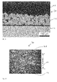
- Fig. 10 shows a cross section of a bonded article 30 bonded in accordance with the above method.
- the bond is continuous, having no cavities or discontinuities.
- the grains of the interlayer 16 have interacted with the parent material of the first and second articles 12, 26, providing a good metallurgical bond.
- the joint interface is not planar (i.e. there is no distinct dividing line between the interlayer 16 and first and second articles 12, 26). Rather, the grains of the interlayer 16 and articles 12, 26 grow into one another across the respective interfaces during bonding, creating an exceptionally strong bond. This bond shown in Fig. 6 has been tested, and has been found to be of satisfactory quality.
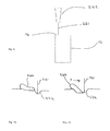
- Figs. 4 and 5 show an alternative bonding method in accordance with the present disclosure.
- the bonding method is similar to the bonding method shown in Figs. 1 and 2 , except that in a first step, the porous interlayer region 116 is produced as a separate preform on a substrate 132.
- the porous pre-form 116 in this embodiment could be formed by any suitable additive manufacturing process, such as cold spraying or laser assisted cold spraying. In the embodiment shown in Fig.
- the porous preform 116 is produced by blown powder deposition, in which powder 134 of a suitable material is directed towards the substrate 132 from a nozzle 136, and enters the path of a laser beam 138 from a laser 140 which briefly brings the powder 134 and the substrate 132 to a molten state before solidifying and raising the overall height of the substrate 132 to form the interlayer 116, layer by layer.
- the laser beam 138 is moved backward and forward across the substrate 132 to build the required interlayer 116, with the beam being maintained substantially perpendicular to the substrate 132 to ensure the energy density is evenly distributed.
- the additive manufacturing process is carried out in either a low oxygen or a low pressure environment to prevent oxidation of the interlayer 116.
- the process is carried out in an inert gas environment (such as argon) having less than 10 parts per million (ppm) of oxygen and less than approximately 5 ppm moisture and a dew point of less than -65°C.
- the process may be carried out in an environment having a pressure of less than 10 -4 Torr (130 Pascals).
- porous interlayer preform 116 is manufactured, the desired surface roughness is formed in a similar process to that of the first embodiment, either via the additive manufacturing process, or via a separate surface treatment step.
- the porous interlayer preform 116 is then interposed between the respective bonding surfaces 14, 28 of the first and second articles 12, 26 and bonded together by applying heat and pressure. Again, the pressure may be applied in two stages, with the second stage having a longer duration and lower pressure than the first.
- the geometry of the preform 116 is similar to that of the interlayer region 16, having a similar porosity, and pores of a similar size and shape.
- the preform 116 may additionally include a thicker section of higher density to impart greater rigidity.
- Bonds of similar strength can be achieved using this method as by the first method. However, it may be more convenient to use this method.
- the pre-forms 116 can be mass produced ahead of time without requiring access to the first and second articles 12, 26, thereby reducing repair times.
- such a process results in an increased part count and requires alignment between the preform and the first and second articles 12, 26.
- chemical incompatibility due to slight differences in alloy composition of the interlayer 116 compared to the articles 12, 26 may result in reduced bond strength.
- Fig. 9 shows a bonded article 30 produced using this method. As can be seen, again, no voids are present, indicating a good quality bond.
- Fig. 6 shows a first step of a third method of bonding first and second articles 12, 26 which seeks to overcome the potential chemical incompatibility problem described above.
- a power beam such as an electron beam or a laser is used to form surface pores 224 in the bonding surface 14 of the first article 12, thereby forming an interlayer region 216 in the bonding surface 14.
- the power beam is provided in the form of an electron beam 241 provided by an electron gun 242.
- the electron beam 241 is rapidly traversed across the bonding surface 14 of the first article 12 in a direction X.
- the electron beam 241 power and rate of movement are adjusted such that a portion of the surface 14 is melted to form a bead 244 of molten metal, and a pore 224.
- the bead 244 is forced in a direction away from the beam 241 by surface tension gradients set up by thermal gradients as a result of the electron beam 241.
- the bead 244 quickly solidifies to form a projection of roughly the shape shown in 244.
- a porous interlayer region 216 is formed consisting of an array of protrusions 244 above the original surface 14 and a corresponding array of pores 224 in the form of intrusions or cavities in the substrate.
- the bonding surface 14 of the first article 12 has a surface roughness parameter of approximately 25 Ra.
- the interlayer region 216 comprises the region of the first article 12 in which the pores 241 and protrusions 244 are formed.
- the thickness of the interlayer region 216 is the distance between the top of the projections 244 and the bottom of the pores 241.
- the porosity of the interlayer 216 is therefore defined as the area of this region 216 not occupied by solid metal prior to the bonding step.
- Fig. 8 shows an alternative interlayer 316.
- the interlayer 316 comprise a first region 346 having a first width in a direction extending parallel to the bonding surfaces, and a second region 348 having a second width greater than the first thickness.
- first and second articles comprise parts of an aerofoil component such as a blade or vane of a gas turbine engine, where the leading edge and central portions of the blade typically have a thicker profile compared to the trailing edge.
- the thickness of the interlayer 316 in a direction normal to the bonding surfaces could vary in a similar manner.
- Both the first region 346 and second region 348 comprise pores 324. However, more pores 324 (and / or larger pores 324) are provided for a given volume of the second region 348 compared to the first region 346 such that the second region 348 has a lower density in comparison to the first region 346. Consequently, when an electric current is passed through the interlayer 316 to heat the interlayer region during the bonding step, the electrical resistance provided by the second region 348 is higher than that provided by the first region 346.
- the relative densities of the first and second regions 346, 348 may be tailored such that the overall heating of the first and second regions 346, 348 is substantially similar. Consequently, the method can be applied to interlayers having non-uniform thickness, while still providing uniform heating, thereby forming a consistent bond between the first and second articles 12, 26 and interlayer region 316.
- the porous interlayer may be formed using a different additive manufacturing technique.
- LACS laser assisted cold spray
- Laser assisted cold spraying is similar to cold spraying, except that the substrate is first pre-treated by heating with a laser, such as a NdYAG laser, to heat the surface prior to the metal powder being deposited on the bonding surface. Depending on the set-up, some particles may be heated in flight by the laser.
- a laser such as a NdYAG laser
- vacuum plasma spraying also known as thermal spraying
- metal particles are heated to above their melting points or to a temperature at which the metal becomes plastic, and then sprayed onto the substrate to form a layer of material.
- a different method may also be employed for obtaining the desired surface profile in the embodiment in which the interlayer is formed in the bonding surface of the first articles.
- the method could comprise one or more of volatisation, laser ablation, and power beam assisted etching.
- the method could comprise an inspection step subsequent to forming the interlayer to determine the size and distribution of the pores or the surface roughness of the bonding surfaces.
- an X-ray or ultrasound non-destructive inspection method could be employed.
- a plurality of porous interlayer regions could be provided between the first and second articles.
- a porous interlayer region could be formed on the bonding surface of each of the first and second articles.
- the first and second articles could comprise dissimilar metals.
- the grain size or chemical composition of the interlayer could be graduated, with larger grains of one chemical composition being provided adjacent the first article, and smaller grains of a different chemical composition being provided adjacent the second article.
- the interlayer could be aligned with the crystallographic orientation of the first and / or second articles to provide further increased bond strength, thereby better matching the material properties of the first and second articles when bonded.
- the invention could be used to bond different types of articles.
- the articles could comprise partially or fully consolidated components produced by a Hot Isostatic Pressing (HIP) process.
- the invention is particularly suitable for high integrity stud welding and for welding high integrity attachment hooks in gas turbine engines.
- the invention could be used for cladding applications for niche applications.
- the invention could be used to create run-off and run-on tabs for friction stir welding applications.
- the invention is particularly well suited to joining of TiAl turbine blades to discs.
- Variations could be provided in the process variables used in the pressure assisted bonding step.
- heat may be provided continuously, or in phases.
- the pressure may also be varied so as to control the upset; this may be phased with the heating.
Landscapes
- Engineering & Computer Science (AREA)
- Mechanical Engineering (AREA)
- Chemical & Material Sciences (AREA)
- Manufacturing & Machinery (AREA)
- Materials Engineering (AREA)
- Physics & Mathematics (AREA)
- Optics & Photonics (AREA)
- Plasma & Fusion (AREA)
- Composite Materials (AREA)
- Pressure Welding/Diffusion-Bonding (AREA)
- Laminated Bodies (AREA)
- Ceramic Products (AREA)
Applications Claiming Priority (2)
| Application Number | Priority Date | Filing Date | Title |
|---|---|---|---|
| GBGB1405988.5A GB201405988D0 (en) | 2014-04-03 | 2014-04-03 | Bonding method |
| GB201406527A GB201406527D0 (en) | 2014-04-03 | 2014-04-11 | Bonding method |
Publications (3)
| Publication Number | Publication Date |
|---|---|
| EP2957376A2 true EP2957376A2 (de) | 2015-12-23 |
| EP2957376A3 EP2957376A3 (de) | 2016-04-20 |
| EP2957376B1 EP2957376B1 (de) | 2019-02-27 |
Family
ID=50776751
Family Applications (1)
| Application Number | Title | Priority Date | Filing Date |
|---|---|---|---|
| EP15158479.4A Active EP2957376B1 (de) | 2014-04-03 | 2015-03-10 | Verfahren zum Herstellen eines verbundenen Artikels unter Verwendung einer poröse Zwischenschichtsregion |
Country Status (3)
| Country | Link |
|---|---|
| US (1) | US9731377B2 (de) |
| EP (1) | EP2957376B1 (de) |
| GB (2) | GB201405988D0 (de) |
Cited By (3)
| Publication number | Priority date | Publication date | Assignee | Title |
|---|---|---|---|---|
| CN108672909A (zh) * | 2018-05-28 | 2018-10-19 | 宁波北仑百晟钣金件制造有限公司 | 一种用于钣金件的焊接工艺 |
| WO2019048641A1 (de) * | 2017-09-08 | 2019-03-14 | Karlsruher Institut für Technologie | VERFAHREN ZUR VERBINDUNG VON WERKSTÜCKEN MITTELS DIFFUSIONSSCHWEIßENS |
| DE102020101472A1 (de) * | 2020-01-22 | 2021-02-11 | Helmholtz-Zentrum Geesthacht Zentrum für Material- und Küstenforschung GmbH | Verfahren und Satz von Ersatzstücken zur Reparatur einer Niederdruckturbinenschaufel aus Titanaluminid |
Families Citing this family (24)
| Publication number | Priority date | Publication date | Assignee | Title |
|---|---|---|---|---|
| US20160023439A1 (en) * | 2014-07-22 | 2016-01-28 | General Electric Company | Method for joining high temperature materials and articles made therewith |
| EP3170602B1 (de) * | 2015-11-19 | 2017-12-27 | LMT Fette Werkzeugtechnik GmbH & Co. KG | Gewindeformer oder -bohrer und verfahren zur herstellung eines gewindeformers oder -bohrers |
| US20170355018A1 (en) | 2016-06-09 | 2017-12-14 | Hamilton Sundstrand Corporation | Powder deposition for additive manufacturing |
| US10765975B2 (en) | 2016-07-01 | 2020-09-08 | Caterpillar Inc. | Filter element and method of manufacturing a filter element |
| US12084776B2 (en) * | 2017-06-20 | 2024-09-10 | Commonwealth Scientific And Industrial Research Organisation | Process for forming wrought structures using cold spray |
| DE102017222182A1 (de) | 2017-12-07 | 2019-06-13 | Helmholtz-Zentrum Geesthacht Zentrum für Material- und Küstenforschung GmbH | Verfahren zum Aufbringen einer Titanaluminidlegierung, Titanaluminidlegierung und Substrat umfassend eine Titanaluminidlegierung |
| US11090861B2 (en) * | 2018-07-26 | 2021-08-17 | General Electric Company | Systems and methods for lateral material transfer in additive manufacturing system |
| US11426818B2 (en) | 2018-08-10 | 2022-08-30 | The Research Foundation for the State University | Additive manufacturing processes and additively manufactured products |
| US10780498B2 (en) * | 2018-08-22 | 2020-09-22 | General Electric Company | Porous tools and methods of making the same |
| CN110936010B (zh) * | 2019-10-25 | 2021-12-14 | 合肥国轩高科动力能源有限公司 | 一种锂电池复合集流体极耳焊接的方法 |
| GB202004947D0 (en) * | 2020-04-03 | 2020-05-20 | Rolls Royce Plc | Joining component bodies |
| CN117245201A (zh) * | 2022-06-09 | 2023-12-19 | 季华实验室 | 用于铝基复合材料焊接的中间层及其制作方法、焊接方法 |
| US12330230B2 (en) * | 2022-08-19 | 2025-06-17 | General Electric Company | Additively manufactured joined parts |
| US20250137387A1 (en) * | 2023-10-27 | 2025-05-01 | Ge Infrastructure Technology Llc | Metal coupon with porous region for component and component with same |
| US20250135588A1 (en) * | 2023-10-27 | 2025-05-01 | Ge Infrastructure Technology Llc | Braze repair using metal coupon with porous region |
| US20250137373A1 (en) * | 2023-10-27 | 2025-05-01 | Ge Infrastructure Technology Llc | Metal coupon with porous stress-relief section, component with same and related method |
| US12576614B2 (en) | 2023-10-27 | 2026-03-17 | Ge Infrastructure Technology Llc | Porous metal coupon with thermal transfer structure for component and related component |
| US12544845B2 (en) * | 2023-10-27 | 2026-02-10 | Ge Infrastructure Technology Llc | Porous metal coupon with braze material infiltration barrier for repairing component, component with same and related method |
| US20250135545A1 (en) * | 2023-10-27 | 2025-05-01 | Ge Infrastructure Technology Llc | Metal porous coupon with anchor for component and component with same |
| US20250135546A1 (en) * | 2023-10-27 | 2025-05-01 | Ge Infrastructure Technology Llc | Method of using metal coupon with porous region for component |
| US20250135533A1 (en) * | 2023-10-27 | 2025-05-01 | Ge Infrastructure Technology Llc | Metal porous region for component printed on replacement region or base region of component |
| US12605768B2 (en) * | 2023-10-27 | 2026-04-21 | Ge Infrastructure Technology Llc | Porous metal coupon with low porosity region for repairing component, component with same and related method |
| US12502713B2 (en) | 2023-10-27 | 2025-12-23 | Ge Infrastructure Technology Llc | Porous metal coupon with sealed cavity for repairing component, component with same and related method |
| US12528133B2 (en) | 2024-01-19 | 2026-01-20 | Ge Infrastructure Technology Llc | Metal coupon with braze reservoir for component, component with same and related method |
Family Cites Families (13)
| Publication number | Priority date | Publication date | Assignee | Title |
|---|---|---|---|---|
| US3716347A (en) | 1970-09-21 | 1973-02-13 | Minnesota Mining & Mfg | Metal parts joined with sintered powdered metal |
| SU1094708A1 (ru) | 1983-03-04 | 1984-05-30 | Предприятие П/Я Р-6476 | Способ диффузионной сварки материалов через пористую промежуточную прокладку |
| SU1100065A1 (ru) | 1983-04-07 | 1984-06-30 | Саратовский Ордена Трудового Красного Знамени Политехнический Институт | Способ диффузионной сварки разнородных материалов через промежуточную пористую прокладку |
| JPH0729859B2 (ja) * | 1985-09-05 | 1995-04-05 | 株式会社東芝 | セラミツクス−金属接合部材 |
| SU1407731A1 (ru) | 1987-01-12 | 1988-07-07 | Институт проблем сверхпластичности металлов АН СССР | Способ сварки давлением с подогревом разнородных материалов |
| SU1449289A1 (ru) * | 1987-06-08 | 1989-01-07 | Московский авиационный технологический институт им.К.Э.Циолковского | Способ диффузионной сварки |
| US6413589B1 (en) * | 1988-11-29 | 2002-07-02 | Chou H. Li | Ceramic coating method |
| RU2184018C1 (ru) | 2000-12-28 | 2002-06-27 | ОАО "Раменское приборостроительное конструкторское бюро" | Способ диффузионной сварки |
| CN101528407B (zh) * | 2006-10-18 | 2012-01-04 | 陶氏环球技术公司 | 粘合铝-硼-碳复合材料的改进方法 |
| GB0701904D0 (en) | 2007-02-01 | 2007-03-14 | Rolls Royce Plc | A method of manufacturing a component by consolidating powder material |
| US8608049B2 (en) * | 2007-10-10 | 2013-12-17 | Zimmer, Inc. | Method for bonding a tantalum structure to a cobalt-alloy substrate |
| GB0913887D0 (en) | 2009-08-10 | 2009-09-16 | A method of joining components | |
| GB0913924D0 (en) | 2009-08-11 | 2009-09-16 | Rolls Royce Plc | Developments in or relating to drum rotors |
-
2014
- 2014-04-03 GB GBGB1405988.5A patent/GB201405988D0/en not_active Ceased
- 2014-04-11 GB GB201406527A patent/GB201406527D0/en not_active Ceased
-
2015
- 2015-03-10 EP EP15158479.4A patent/EP2957376B1/de active Active
- 2015-03-12 US US14/645,956 patent/US9731377B2/en active Active
Cited By (3)
| Publication number | Priority date | Publication date | Assignee | Title |
|---|---|---|---|---|
| WO2019048641A1 (de) * | 2017-09-08 | 2019-03-14 | Karlsruher Institut für Technologie | VERFAHREN ZUR VERBINDUNG VON WERKSTÜCKEN MITTELS DIFFUSIONSSCHWEIßENS |
| CN108672909A (zh) * | 2018-05-28 | 2018-10-19 | 宁波北仑百晟钣金件制造有限公司 | 一种用于钣金件的焊接工艺 |
| DE102020101472A1 (de) * | 2020-01-22 | 2021-02-11 | Helmholtz-Zentrum Geesthacht Zentrum für Material- und Küstenforschung GmbH | Verfahren und Satz von Ersatzstücken zur Reparatur einer Niederdruckturbinenschaufel aus Titanaluminid |
Also Published As
| Publication number | Publication date |
|---|---|
| GB201406527D0 (en) | 2014-05-28 |
| GB201405988D0 (en) | 2014-05-21 |
| EP2957376B1 (de) | 2019-02-27 |
| US9731377B2 (en) | 2017-08-15 |
| EP2957376A3 (de) | 2016-04-20 |
| US20150283642A1 (en) | 2015-10-08 |
Similar Documents
| Publication | Publication Date | Title |
|---|---|---|
| EP2957376B1 (de) | Verfahren zum Herstellen eines verbundenen Artikels unter Verwendung einer poröse Zwischenschichtsregion | |
| EP3693105B1 (de) | Verfahren zur herstellung eines bauteils | |
| Hotz et al. | Additive manufacturing of functionally graded Ti-Al structures by laser-based direct energy deposition | |
| JP7433663B2 (ja) | 異材固相接合方法、異材固相接合構造物及び異材固相接合装置 | |
| Chen et al. | Surface roughness and fatigue properties of selective laser melted Ti–6Al–4V alloy | |
| JP6170159B2 (ja) | 中空チタンファンブレードのアルミニウムろう付け | |
| RS65004A (sr) | Popravljanje površine vatrostalnog metala i legure putem oblikovanja i topljenja laserom | |
| CN114206535B (zh) | 异种材料固相接合方法及异种材料固相接合构造物 | |
| Rao et al. | Effect of process parameters on powder bed fusion maraging steel 300: a review | |
| JP6188678B2 (ja) | フラッシュ焼結によって複雑な形状を有する部品を製造するための方法、およびそのような方法を実施するための装置 | |
| CN108998698B (zh) | 超合金制品、部件及其处理方法 | |
| US10174414B2 (en) | Manufactured article and method | |
| EP2762257A1 (de) | Lötverfahren, Lötanordnung, und gelöteter Artikel | |
| JP7051522B2 (ja) | ハイブリッド物品、ハイブリッド物品を形成するための方法、および溶接のための方法 | |
| CN106956089B (zh) | 混合制品、用于形成混合制品的方法和用于封闭孔口的方法 | |
| Marstatt et al. | Formation of a diffusion-based intermetallic interface layer in friction stir welded dissimilar Al-Cu lap joints | |
| JPH0741930A (ja) | 金属溶射による材料の接合方法 | |
| EP2674243B1 (de) | Verfahren zur reparatur von metallgegenständen | |
| KR20130132325A (ko) | 플랜지를 구비하는 타겟의 제조 방법 | |
| US20220281027A1 (en) | Electron-beam welding nickel-based superalloys, and device | |
| RU2619419C2 (ru) | Способ нанесения алюминида титана и изделие с поверхностью из алюминида титана | |
| EP3868495A1 (de) | Verfahren zur laminierung einer gehärteten schicht und herstellungsverfahren für einen laminierten formartikel | |
| WO2022078630A1 (en) | Method of manufacturing a build plate for use in an additive manufacturing process | |
| JPWO2007052743A1 (ja) | スパッタリングターゲットおよびその製造方法 | |
| Osipovich et al. | Regularities of the formation of the polymetallic samples of the Fe-Ti, Fe-Cu-Ti system, produced by the wire-feed electron beam additive manufacturing |
Legal Events
| Date | Code | Title | Description |
|---|---|---|---|
| PUAI | Public reference made under article 153(3) epc to a published international application that has entered the european phase |
Free format text: ORIGINAL CODE: 0009012 |
|
| AK | Designated contracting states |
Kind code of ref document: A2 Designated state(s): AL AT BE BG CH CY CZ DE DK EE ES FI FR GB GR HR HU IE IS IT LI LT LU LV MC MK MT NL NO PL PT RO RS SE SI SK SM TR |
|
| AX | Request for extension of the european patent |
Extension state: BA ME |
|
| PUAL | Search report despatched |
Free format text: ORIGINAL CODE: 0009013 |
|
| AK | Designated contracting states |
Kind code of ref document: A3 Designated state(s): AL AT BE BG CH CY CZ DE DK EE ES FI FR GB GR HR HU IE IS IT LI LT LU LV MC MK MT NL NO PL PT RO RS SE SI SK SM TR |
|
| AX | Request for extension of the european patent |
Extension state: BA ME |
|
| RIC1 | Information provided on ipc code assigned before grant |
Ipc: B23K 20/24 20060101ALI20160311BHEP Ipc: B23K 20/233 20060101ALI20160311BHEP Ipc: B23P 6/00 20060101ALI20160311BHEP Ipc: B23K 103/14 20060101ALI20160311BHEP Ipc: B23K 101/00 20060101ALI20160311BHEP Ipc: B23K 26/34 20140101ALI20160311BHEP Ipc: B23K 20/16 20060101ALI20160311BHEP Ipc: B22F 3/105 20060101ALI20160311BHEP Ipc: B23K 20/02 20060101AFI20160311BHEP |
|
| 17P | Request for examination filed |
Effective date: 20160425 |
|
| RBV | Designated contracting states (corrected) |
Designated state(s): AL AT BE BG CH CY CZ DE DK EE ES FI FR GB GR HR HU IE IS IT LI LT LU LV MC MK MT NL NO PL PT RO RS SE SI SK SM TR |
|
| GRAP | Despatch of communication of intention to grant a patent |
Free format text: ORIGINAL CODE: EPIDOSNIGR1 |
|
| STAA | Information on the status of an ep patent application or granted ep patent |
Free format text: STATUS: GRANT OF PATENT IS INTENDED |
|
| INTG | Intention to grant announced |
Effective date: 20181214 |
|
| GRAS | Grant fee paid |
Free format text: ORIGINAL CODE: EPIDOSNIGR3 |
|
| GRAA | (expected) grant |
Free format text: ORIGINAL CODE: 0009210 |
|
| STAA | Information on the status of an ep patent application or granted ep patent |
Free format text: STATUS: THE PATENT HAS BEEN GRANTED |
|
| AK | Designated contracting states |
Kind code of ref document: B1 Designated state(s): AL AT BE BG CH CY CZ DE DK EE ES FI FR GB GR HR HU IE IS IT LI LT LU LV MC MK MT NL NO PL PT RO RS SE SI SK SM TR |
|
| REG | Reference to a national code |
Ref country code: GB Ref legal event code: FG4D |
|
| REG | Reference to a national code |
Ref country code: CH Ref legal event code: EP |
|
| REG | Reference to a national code |
Ref country code: AT Ref legal event code: REF Ref document number: 1100625 Country of ref document: AT Kind code of ref document: T Effective date: 20190315 |
|
| REG | Reference to a national code |
Ref country code: IE Ref legal event code: FG4D |
|
| REG | Reference to a national code |
Ref country code: DE Ref legal event code: R096 Ref document number: 602015025185 Country of ref document: DE |
|
| REG | Reference to a national code |
Ref country code: NL Ref legal event code: MP Effective date: 20190227 |
|
| REG | Reference to a national code |
Ref country code: LT Ref legal event code: MG4D |
|
| PG25 | Lapsed in a contracting state [announced via postgrant information from national office to epo] |
Ref country code: NL Free format text: LAPSE BECAUSE OF FAILURE TO SUBMIT A TRANSLATION OF THE DESCRIPTION OR TO PAY THE FEE WITHIN THE PRESCRIBED TIME-LIMIT Effective date: 20190227 Ref country code: SE Free format text: LAPSE BECAUSE OF FAILURE TO SUBMIT A TRANSLATION OF THE DESCRIPTION OR TO PAY THE FEE WITHIN THE PRESCRIBED TIME-LIMIT Effective date: 20190227 Ref country code: LT Free format text: LAPSE BECAUSE OF FAILURE TO SUBMIT A TRANSLATION OF THE DESCRIPTION OR TO PAY THE FEE WITHIN THE PRESCRIBED TIME-LIMIT Effective date: 20190227 Ref country code: NO Free format text: LAPSE BECAUSE OF FAILURE TO SUBMIT A TRANSLATION OF THE DESCRIPTION OR TO PAY THE FEE WITHIN THE PRESCRIBED TIME-LIMIT Effective date: 20190527 Ref country code: PT Free format text: LAPSE BECAUSE OF FAILURE TO SUBMIT A TRANSLATION OF THE DESCRIPTION OR TO PAY THE FEE WITHIN THE PRESCRIBED TIME-LIMIT Effective date: 20190627 Ref country code: FI Free format text: LAPSE BECAUSE OF FAILURE TO SUBMIT A TRANSLATION OF THE DESCRIPTION OR TO PAY THE FEE WITHIN THE PRESCRIBED TIME-LIMIT Effective date: 20190227 |
|
| PG25 | Lapsed in a contracting state [announced via postgrant information from national office to epo] |
Ref country code: IS Free format text: LAPSE BECAUSE OF FAILURE TO SUBMIT A TRANSLATION OF THE DESCRIPTION OR TO PAY THE FEE WITHIN THE PRESCRIBED TIME-LIMIT Effective date: 20190627 Ref country code: BG Free format text: LAPSE BECAUSE OF FAILURE TO SUBMIT A TRANSLATION OF THE DESCRIPTION OR TO PAY THE FEE WITHIN THE PRESCRIBED TIME-LIMIT Effective date: 20190527 Ref country code: LV Free format text: LAPSE BECAUSE OF FAILURE TO SUBMIT A TRANSLATION OF THE DESCRIPTION OR TO PAY THE FEE WITHIN THE PRESCRIBED TIME-LIMIT Effective date: 20190227 Ref country code: RS Free format text: LAPSE BECAUSE OF FAILURE TO SUBMIT A TRANSLATION OF THE DESCRIPTION OR TO PAY THE FEE WITHIN THE PRESCRIBED TIME-LIMIT Effective date: 20190227 Ref country code: HR Free format text: LAPSE BECAUSE OF FAILURE TO SUBMIT A TRANSLATION OF THE DESCRIPTION OR TO PAY THE FEE WITHIN THE PRESCRIBED TIME-LIMIT Effective date: 20190227 Ref country code: GR Free format text: LAPSE BECAUSE OF FAILURE TO SUBMIT A TRANSLATION OF THE DESCRIPTION OR TO PAY THE FEE WITHIN THE PRESCRIBED TIME-LIMIT Effective date: 20190528 |
|
| REG | Reference to a national code |
Ref country code: AT Ref legal event code: MK05 Ref document number: 1100625 Country of ref document: AT Kind code of ref document: T Effective date: 20190227 |
|
| PG25 | Lapsed in a contracting state [announced via postgrant information from national office to epo] |
Ref country code: AL Free format text: LAPSE BECAUSE OF FAILURE TO SUBMIT A TRANSLATION OF THE DESCRIPTION OR TO PAY THE FEE WITHIN THE PRESCRIBED TIME-LIMIT Effective date: 20190227 Ref country code: ES Free format text: LAPSE BECAUSE OF FAILURE TO SUBMIT A TRANSLATION OF THE DESCRIPTION OR TO PAY THE FEE WITHIN THE PRESCRIBED TIME-LIMIT Effective date: 20190227 Ref country code: CZ Free format text: LAPSE BECAUSE OF FAILURE TO SUBMIT A TRANSLATION OF THE DESCRIPTION OR TO PAY THE FEE WITHIN THE PRESCRIBED TIME-LIMIT Effective date: 20190227 Ref country code: SK Free format text: LAPSE BECAUSE OF FAILURE TO SUBMIT A TRANSLATION OF THE DESCRIPTION OR TO PAY THE FEE WITHIN THE PRESCRIBED TIME-LIMIT Effective date: 20190227 Ref country code: IT Free format text: LAPSE BECAUSE OF FAILURE TO SUBMIT A TRANSLATION OF THE DESCRIPTION OR TO PAY THE FEE WITHIN THE PRESCRIBED TIME-LIMIT Effective date: 20190227 Ref country code: RO Free format text: LAPSE BECAUSE OF FAILURE TO SUBMIT A TRANSLATION OF THE DESCRIPTION OR TO PAY THE FEE WITHIN THE PRESCRIBED TIME-LIMIT Effective date: 20190227 Ref country code: DK Free format text: LAPSE BECAUSE OF FAILURE TO SUBMIT A TRANSLATION OF THE DESCRIPTION OR TO PAY THE FEE WITHIN THE PRESCRIBED TIME-LIMIT Effective date: 20190227 Ref country code: EE Free format text: LAPSE BECAUSE OF FAILURE TO SUBMIT A TRANSLATION OF THE DESCRIPTION OR TO PAY THE FEE WITHIN THE PRESCRIBED TIME-LIMIT Effective date: 20190227 |
|
| REG | Reference to a national code |
Ref country code: CH Ref legal event code: PL |
|
| REG | Reference to a national code |
Ref country code: DE Ref legal event code: R097 Ref document number: 602015025185 Country of ref document: DE |
|
| PG25 | Lapsed in a contracting state [announced via postgrant information from national office to epo] |
Ref country code: PL Free format text: LAPSE BECAUSE OF FAILURE TO SUBMIT A TRANSLATION OF THE DESCRIPTION OR TO PAY THE FEE WITHIN THE PRESCRIBED TIME-LIMIT Effective date: 20190227 Ref country code: SM Free format text: LAPSE BECAUSE OF FAILURE TO SUBMIT A TRANSLATION OF THE DESCRIPTION OR TO PAY THE FEE WITHIN THE PRESCRIBED TIME-LIMIT Effective date: 20190227 Ref country code: LU Free format text: LAPSE BECAUSE OF NON-PAYMENT OF DUE FEES Effective date: 20190310 |
|
| REG | Reference to a national code |
Ref country code: BE Ref legal event code: MM Effective date: 20190331 |
|
| PG25 | Lapsed in a contracting state [announced via postgrant information from national office to epo] |
Ref country code: MC Free format text: LAPSE BECAUSE OF FAILURE TO SUBMIT A TRANSLATION OF THE DESCRIPTION OR TO PAY THE FEE WITHIN THE PRESCRIBED TIME-LIMIT Effective date: 20190227 Ref country code: AT Free format text: LAPSE BECAUSE OF FAILURE TO SUBMIT A TRANSLATION OF THE DESCRIPTION OR TO PAY THE FEE WITHIN THE PRESCRIBED TIME-LIMIT Effective date: 20190227 |
|
| PLBE | No opposition filed within time limit |
Free format text: ORIGINAL CODE: 0009261 |
|
| STAA | Information on the status of an ep patent application or granted ep patent |
Free format text: STATUS: NO OPPOSITION FILED WITHIN TIME LIMIT |
|
| PG25 | Lapsed in a contracting state [announced via postgrant information from national office to epo] |
Ref country code: CH Free format text: LAPSE BECAUSE OF NON-PAYMENT OF DUE FEES Effective date: 20190331 Ref country code: LI Free format text: LAPSE BECAUSE OF NON-PAYMENT OF DUE FEES Effective date: 20190331 Ref country code: IE Free format text: LAPSE BECAUSE OF NON-PAYMENT OF DUE FEES Effective date: 20190310 |
|
| 26N | No opposition filed |
Effective date: 20191128 |
|
| PG25 | Lapsed in a contracting state [announced via postgrant information from national office to epo] |
Ref country code: SI Free format text: LAPSE BECAUSE OF FAILURE TO SUBMIT A TRANSLATION OF THE DESCRIPTION OR TO PAY THE FEE WITHIN THE PRESCRIBED TIME-LIMIT Effective date: 20190227 Ref country code: BE Free format text: LAPSE BECAUSE OF NON-PAYMENT OF DUE FEES Effective date: 20190331 |
|
| PG25 | Lapsed in a contracting state [announced via postgrant information from national office to epo] |
Ref country code: TR Free format text: LAPSE BECAUSE OF FAILURE TO SUBMIT A TRANSLATION OF THE DESCRIPTION OR TO PAY THE FEE WITHIN THE PRESCRIBED TIME-LIMIT Effective date: 20190227 |
|
| PG25 | Lapsed in a contracting state [announced via postgrant information from national office to epo] |
Ref country code: MT Free format text: LAPSE BECAUSE OF NON-PAYMENT OF DUE FEES Effective date: 20190310 |
|
| PG25 | Lapsed in a contracting state [announced via postgrant information from national office to epo] |
Ref country code: CY Free format text: LAPSE BECAUSE OF FAILURE TO SUBMIT A TRANSLATION OF THE DESCRIPTION OR TO PAY THE FEE WITHIN THE PRESCRIBED TIME-LIMIT Effective date: 20190227 |
|
| PG25 | Lapsed in a contracting state [announced via postgrant information from national office to epo] |
Ref country code: HU Free format text: LAPSE BECAUSE OF FAILURE TO SUBMIT A TRANSLATION OF THE DESCRIPTION OR TO PAY THE FEE WITHIN THE PRESCRIBED TIME-LIMIT; INVALID AB INITIO Effective date: 20150310 |
|
| PG25 | Lapsed in a contracting state [announced via postgrant information from national office to epo] |
Ref country code: MK Free format text: LAPSE BECAUSE OF FAILURE TO SUBMIT A TRANSLATION OF THE DESCRIPTION OR TO PAY THE FEE WITHIN THE PRESCRIBED TIME-LIMIT Effective date: 20190227 |
|
| P01 | Opt-out of the competence of the unified patent court (upc) registered |
Effective date: 20230528 |
|
| PGFP | Annual fee paid to national office [announced via postgrant information from national office to epo] |
Ref country code: GB Payment date: 20260323 Year of fee payment: 12 |
|
| PGFP | Annual fee paid to national office [announced via postgrant information from national office to epo] |
Ref country code: DE Payment date: 20260320 Year of fee payment: 12 |
|
| PGFP | Annual fee paid to national office [announced via postgrant information from national office to epo] |
Ref country code: FR Payment date: 20260323 Year of fee payment: 12 |