EP2957486A2 - Dispositif de guidage réglable en hauteur pour un appareil de travail - Google Patents
Dispositif de guidage réglable en hauteur pour un appareil de travail Download PDFInfo
- Publication number
- EP2957486A2 EP2957486A2 EP15001087.4A EP15001087A EP2957486A2 EP 2957486 A2 EP2957486 A2 EP 2957486A2 EP 15001087 A EP15001087 A EP 15001087A EP 2957486 A2 EP2957486 A2 EP 2957486A2
- Authority
- EP
- European Patent Office
- Prior art keywords
- drawbar
- support
- guide device
- holding
- spindle
- Prior art date
- Legal status (The legal status is an assumption and is not a legal conclusion. Google has not performed a legal analysis and makes no representation as to the accuracy of the status listed.)
- Granted
Links
Images


Classifications
-
- B—PERFORMING OPERATIONS; TRANSPORTING
- B62—LAND VEHICLES FOR TRAVELLING OTHERWISE THAN ON RAILS
- B62D—MOTOR VEHICLES; TRAILERS
- B62D49/00—Tractors
- B62D49/06—Tractors adapted for multi-purpose use
- B62D49/065—Coupling of multi-purpose tractors with equipment
-
- A—HUMAN NECESSITIES
- A01—AGRICULTURE; FORESTRY; ANIMAL HUSBANDRY; HUNTING; TRAPPING; FISHING
- A01D—HARVESTING; MOWING
- A01D34/00—Mowers; Mowing apparatus of harvesters
- A01D34/01—Mowers; Mowing apparatus of harvesters characterised by features relating to the type of cutting apparatus
- A01D34/412—Mowers; Mowing apparatus of harvesters characterised by features relating to the type of cutting apparatus having rotating cutters
- A01D34/63—Mowers; Mowing apparatus of harvesters characterised by features relating to the type of cutting apparatus having rotating cutters having cutters rotating about a vertical axis
- A01D34/82—Other details
- A01D34/824—Handle arrangements
Definitions
- the invention relates to a height-adjustable guide device for a working device.
- Such implements are, for example, mowers or, in particular, soil compaction devices, such as e.g. Vibratory plates or vibratory rollers.
- soil compaction devices consist essentially of a lower mass with a ground contact element which is moved over the soil to be compacted and subjected to vibrations which are generated by a vibration exciter.
- the vibration exciter is usually a force exciter, in which e.g. two counter-rotating unbalanced shafts generate a resultant force, which bring about the desired oscillation.
- an upper mass movable relative to the lower mass, which has a drive, e.g. an internal combustion engine, a machine frame and optionally a drawbar for guiding the vibrating plate.
- a drive e.g. an internal combustion engine
- a machine frame e.g. a machine frame
- a drawbar for guiding the vibrating plate.
- To the upper mass usually also a fuel tank, controls and - if present - parts of a hydraulic system are counted.
- Such soil compacting devices may be used, for example, in trenches and are also intended to undercut low obstacles, such as channel struts, power cables, sewage pipes, etc., that intersect the trench. Also, when using other tools, which are guided by a drawbar, it may be necessary to undercut obstacles. To accomplish this, guide rods of the implements must be height adjustable.
- a height adjustment of the guide bar is typically achieved by means of tools (for example: loosening a screw connection - lowering the guide bar - tightening the screw connection or: releasing a lock nut - completely screwing back a threaded spindle - tightening the lock nut). But it is also possible to adjust the height of the guide rods without tools by completely turning back a non-countered threaded spindle.
- the invention is therefore based on the object to provide a guide device that can be brought quickly, without tools and without much effort in a position that makes it possible to drive under obstacles, and can be returned with just as little effort in a previously set working position.
- a guide device for guiding an implement comprises: a connector; a drawbar member connected to the connecting member and movable relative to the connecting member to a first position or a second position; and a support member having a support stop that holds the drawbar member in the first position by supporting the support stopper on a support member.
- the drawbar element via the connecting element with the working device is connected and either the holding element is connected to the connecting element and the support member movably connected to the drawbar element or the holding element is connected to the drawbar element and the support member movably connected to the connecting element.
- the drawbar element after releasing the support stop from the holding element in the second position can be pivoted.
- a drawbar is supported by means of a support member such that it is held in a first position corresponding to a working position.
- the support takes place here solely due to the weight of the drawbar element, without any further fixation the drawbar element or the support element by a jamming, screwing, etc. is necessary.
- Due to the mutually movable connections of the components of the guide device it is possible to release the support stop of the support member from the holding element, so that the gravitational support of the drawbar element is eliminated, and then to bring the drawbar in a lower second position, which allows obstacles to go under.
- the connecting element may in this case be formed as an integral part of the working device, e.g. as part of an upper mass of a soil compaction device.
- the connecting element may be formed as a separate element, which is connectable to the working device.
- a further mechanical securing between the retaining element and the support element may be provided.
- This may, for example, be a latching mechanism that can be easily released, e.g. by hand.
- an additional assurance in the first position ie in the ordinary working mode, ensures that prevents unintentional release of the support member from the support member. Since this fuse is easy to solve, the tiller element can still be quickly brought into the second position.
- the support stop can then be releasable from the holding element when the drawbar element is pivoted upwards with respect to the connecting element in the vertical direction. Subsequently, the drawbar element can then be pivoted into the second position when the support element released from the holding element is swung out and the drawbar element is pivoted downwards in the vertical direction.
- the tiller element can be pivoted from the second position in a vertical upward direction to the first position and then held in the first position when the support element is pivoted into the holding element.
- the support stop may comprise a transmission element and be releasable by exerting a force on the transmission element from the retaining element. This makes it possible to release the support element without tools from the holding element. This can be done for example by a manual exercise of the operator on one end of the support member and a subsequent pivoting of the support element. Alternatively or additionally, the support element can also be arranged displaceably. The support element is then removed by a linear movement or a combination of a linear movement with a pivoting movement of the holding element. It is also possible that the support element is swung or moved by an operator with a foot or other body part of the operator of the guide device. This allows easy and uncomplicated operation of the height adjustment of the guide device.
- a spring element can hold the support element resiliently in a starting position, in which the support element holds the drawbar element in the first position.
- the pivoting of the support element is thus carried out against the resilient action of the spring element. This ensures, on the one hand, that the vibrations generated by the soil compaction device, which are transmitted via the drawbar element, the holding element and the support element to the drawbar element, are damped by the spring element.
- the spring element ensures that the support member is moved back in the absence of an external force in the starting position and thus the support stop of the support member when returning the drawbar element from the second in the first position automatically stops in the holding element. This leads to a simplification of the structure of the guide device.
- the support element may have a height adjustment element for setting an angular position between the connecting element and the drawbar element.
- a working position in the first position can be set exactly to an operator of the working device in order to allow as stress-free, upright working as possible.
- the drawbar element of the guide device can be quickly brought from the most ergonomically comfortable position into a position suitable for driving under obstacles, and the operator's least-stressing first position of the drawbar element can be resumed as quickly.
- the burden for an operator of the working device when driving under several obstacles significantly reduced.
- the height adjustment element may comprise a bar segment with latching recesses and the angular position between the connecting element and the drawbar element in the first position may be adjustable by clamping a fastening means in one of the recesses of the bar segment. This allows a simple adjustment of the working height in the first position, which has an increased stability by clamping by means of a fastening means, such as a screw or a bolt.
- the holding element may be connected to the connecting element and the supporting element may be movably connected to the drawbar element.
- the height adjustment element may have a spindle and the connection of the support element with the drawbar element may be formed as a movably connected threaded block.
- the angular position between the connecting element and the drawbar element in the first position by screwing the spindle can be adjusted in the threaded block. This allows easy, tool-free adjustment of the working height in the first position.
- the angular position between the connecting element and the drawbar element in the first position can also be adjusted by changing the position of the holding element. This provides increased flexibility in adjusting the working height.
- the support member may be both pivotable about a horizontal axis and pivotable about a vertical axis. This ensures maximum flexibility in the design of the guide device according to the invention.
- the connecting element may have a first fixing element.
- the support member may comprise a second fixing member and the first fixing member may then engage with the second fixing member and hold the drawbar member in a third position when the drawbar member occupies the third position after pivoting in a vertical upward direction.
- the second fixing element can then be released from the first fixing element, when the support element is swung out or moved and the third position can be located at the intended use of the guide device above the first position.
- This third position can for example be a vertical position of the drawbar element, as required for space-saving transport of the implement.
- the third position is thus typically not a position required during operation, but rather a permanent fixation of the tiller element, e.g. for transport or storage.
- drawbar element can be quickly brought back into the first position by pivoting or moving the support member. This makes it possible to safely transport the implement with the associated guide device and still make it ready for work quickly.
- the holding element may be connected to the drawbar element and the support element may be movably connected to the connecting element. This corresponds to a mechanical reversal of the developments described above, in which the position of the holding element and the support element on the connecting element and the drawbar element are interchanged.
- the height adjustment element has a spindle; the connection of the support element to the connecting element is designed as a movably connected threaded block; and that the angular position between the connecting element and the drawbar element in the first position by screwing the spindle is adjustable in the threaded block.
- the angular position between the connecting element and the drawbar element in the first position can be adjustable by changing the position of the holding element on the drawbar element.
- the support element can be pivotable relative to the connecting element about a horizontal or a vertical axis.
- the guide device in mechanical reversal can be configured such that the drawbar element has a first fixing element; the support element has a second fixing element; the first fixing element then engages with the second fixing element and holds the drawbar element in a third position when the drawbar element assumes the third position after pivoting in a vertical upward direction; the second fixing element is then released from the first fixing element when the support element is swung out; and that, when the guide device is used as intended, the third position is above the first position.
- the guide device according to the invention can be used to guide a soil compacting device, in particular a vibrating plate or a vibrating roller.
- a soil compacting device in particular a vibrating plate or a vibrating roller.
- FIG. 1A to 1C show an embodiment of a guide device 100 for guiding a working device, which allows a rapid, tool-free and uncomplicated lowering of a drawbar element 130 from a first position to a second position.
- the implement may be, for example, a soil compaction device, such as a hand-held vibratory plate or compaction roller, a mower, or other machines having a tiller or a handle exceeding the machine height, with which obstacles are to be traversed.
- a soil compaction device such as a hand-held vibratory plate or compaction roller, a mower, or other machines having a tiller or a handle exceeding the machine height, with which obstacles are to be traversed.
- FIG. 1A shows the guide device 100 in the first position.
- the guide device 100 has a connecting element 120, which serves to connect the guide device 100 with the working device, not shown.
- the connecting element 120 is firmly connected to the working device, for example with the upper mass of a soil compacting device.
- the connecting element 120 can be connected to the working device, for example by fastening means, such as screws, rivets or bolts, in such a manner that the connecting element 120 can be released from the working device again by inserting a tool.
- the connecting element 120 may also be connected, for example by welding, so firmly to the working device that it can no longer be detached from the working device.
- the connector 120 may be an integral part of the implement.
- the connecting element 120 may be integrated in the upper mass of the soil compacting device.
- the drawbar element 130 is pivotally connected.
- the drawbar element 130 is thus above the connecting element 120 connectable or connected to the implement.
- the tiller element 130 serves to guide the implement by a user.
- the tiller element 130 may include a handle or the like that allows the user to control the implement in a desired direction.
- the drawbar element 130 is connected to the connecting element 120 such that it can be moved relative to the connecting element 120 in a first position or a second position.
- the tiller element 130 may be a tiller or a handle that exceeds the height of the implement.
- the tiller element 130 is in the first position.
- the connection of the drawbar element 130 to the connecting element 120 can, as in FIG. 1A illustrated, be designed such that the drawbar element 130 is pivotable about a horizontal axis 125.
- the drawbar element 130 can be pivoted vertically upwards and downwards relative to the connecting element 120.
- the drawbar element 130 may also be connected to the connecting element 120 in such a way that it can be pivoted about a different axis than the horizontal axis.
- the drawbar element 130 can be displaceable relative to the connecting element 120.
- the tiller element 130 may be linearly displaceable in the vertical direction.
- a support element 140 is movably connected to the drawbar element 130.
- the support member 140 may be connected to the drawbar member 130 such that, as in FIG. 1A to 1C shown pivotable about an axis 135.
- the axis 135 can, as in FIG. 1A to 1C It may be a horizontal axis, but it may also be a vertical axis or an axis lying between the horizontal and vertical.
- the support member 140 may be connected to the drawbar member 130 such that it is linearly displaceable.
- the support member 140 along the axis 135, for example by a guide rail or by means of a slotted guide, from the image plane of FIG. 1A to be moved out.
- a retaining element 150 is connected to the connecting element 120.
- the holding member 150 is not movable with respect to the connecting member 120 during operation of the working device.
- the retaining element 150 may be an integral part of the connecting element 120, but it may also be attached to the connecting element 120 by fastening means, so that the exact position of the retaining element 150 can be changed to the connecting element 120 by using tools.
- the retaining element 150 can be for example a dome, but it can also be a simple metal bolt or a recess in the connecting element 120.
- the holding element 150 is attached to the connecting element 120 such that a supporting stop 145 of the supporting element 140 is supported on the holding element 150 in the first position of the drawbar element 130. Due to the weight of the drawbar element 130, the support stop 145 of the support element 140 is pressed firmly onto the holding element 150 and the resulting counterforce keeps the drawbar element 130 in the first position.
- an additional mechanical security for fixing the support stop 145 on the holding element 150 may be formed, e.g. by a locking pin or other fixing elements.
- the support member 140 may, as in FIG. 1A to 1C represented, a bar segment or a rod.
- the support element 140 can also be embodied in any other form that allows the support element 140 to be securely supported in the retaining element 150.
- the support member 140 may be in the form of a stiff spring, triangle, or other regular geometric figure.
- the support element 140 may have the form of a spindle or a bar segment with latching recesses.
- the support member 140 can be resiliently held in an initial position in which the support member 140 holds the drawbar member 130 in the first position.
- the support element 140 may be connected to a spring element which is attached to the connecting element 120, the drawbar element 130 or on the holding element 150, and the support member 140 in deflection or displacement against the action of the spring element by eg pulling or pushing back into the Starting position moves.
- the spring element may in this case be, for example, a metal or plastic spring.
- the connection of the support element 140 to the drawbar element 130 may be formed as one or more, for example two, rubber buffers, which then form the spring element.
- the support member 140 is then resilient and hinged in the or the rubber buffer (s) and the pivoting of the support member is effected by a deformation of the rubber buffer. At the same time, the force building up against the deformation in the rubber buffer brings the support element 140 back into the starting position when no external force acts on the support element.
- the retaining element 150 can also have any shape that allows the support stop 145 of the supporting element 140 to be securely supported in the retaining element 150.
- the shape of the retaining element 150 may be adapted to the geometric shape of the support element, e.g. as a correspondingly shaped recess in the connecting element or as a dome with a corresponding geometric shape, which is mounted on the connecting element 120.
- the support member 140 is pivoted during lifting of the drawbar 130 so that when lowering the drawbar 130 no seizing of the support stop 145 on the support member 150 occurs that could prevent lowering.
- the support element 140 can be displaced linearly in such a way that when the drawbar element 130 is lowered, no fixed seating of the support stop 145 on the holding element 150 occurs.
- the support element 140 for example, along one of the image plane of FIG. 1A to 1C pointing out direction so far that no interaction between the support stopper 145 and the holding member 150 may occur more. This can be done for example by means of a guide rail or a link guide.
- a swiveling movement can be combined with a linear displacement movement in order to avoid interaction between the support stop 145 and the retaining element 150 when the drawbar element 130 is lowered.
- the support stop 145 of the support member 140 is pivoted about the horizontal axis 135 away from the connecting member 120 to a to ensure unimpeded lowering of the drawbar element 130.
- the support stop can be pivoted in the direction of the connecting element 120 with a corresponding shaping of the connecting element 120, the drawbar element 130 and the retaining element 150.
- the support member 140 may be pivoted about a vertical axis or an axis interpolated between the horizontal and the vertical.
- the drawbar element 130 can rest on the holding element 150.
- the tiller element 130 can also be held in the second position by another, not shown, component of the guide device 100, such as a bolt or an axle on the connecting element 120 or retaining element 150.
- the tiller element 130 can be brought from the second position to the first position just as quickly.
- the drawbar element 130 is vertically pivoted upward from the second position such that by pivoting and / or displacement of the support element 140 the secure mounting of the drawbar element 130 is ensured via the support element 140 and the holding element 150 in the first position.
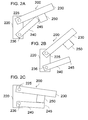
- a holding element 250 is not connected to a connecting element 220, but with a drawbar element 230, which analogous to in FIG. 1A to 1C shown embodiment via an axis 225 to the connecting element 220 is movably connected.
- a support element 240 is then not connected to the tiller element 230, but to the connection element 220.
- the support element 240 may be connected to the connection element 220 via an axle 236, which allows a swinging out and / or displacement of the support element 240.
- the axis 236 may be formed in the vertical direction, in the horizontal direction or in a direction between the vertical and horizontal.
- FIG. 2A to 2C illustrated embodiment provides a mechanical reversal of in Fig. 1A to 1C
- the tiller element 230 is thus in turn held by supporting a support stop 245 of the support member 240 on the holding member 250 in the first position.
- FIG. 2C shown second position.
- the holding in the first position is due to the weight of the tiller element 230, which presses the support stop 245 on the holding member 250, whereby a counterforce is generated, which holds the tiller element 230 in the first position.
- the support stop 245 is released from the holding element 250 and the support element 240 is swung out, for example downwards, as in FIG FIG. 2 B shown and / or moved the tiller element 230 takes the second, suitable for driving under obstacle position.
- the drawbar element 230 can in this case be held in the second position by resting on the support element 240, but it can also be held in the second position by a further component of the guide device 200.
- FIG. 2A to 2C illustrated embodiment possible to bring the tiller element 230 quickly and easily from a first ergonomic working position to a second position, which allows the driving under obstacles.
- FIG. 1A to 1C can be described in the FIG. 2A to 2C represented elements take any other than the form shown, as long as a gravitational support of the support stop 245 in the holding member 250 is possible, which holds the drawbar member 230 in the first position so that it, as described above, can be quickly and easily lowered into the second position.
- the components of the guide device 200 may be those described in the above FIG. 1A to 1C assume for the guide device 100 described forms.
- FIG. 3 shows an embodiment of a guide device 300, which is connected to a serving as a working soil compaction device 310.
- the guide device 300 has a tiller block 320 serving as a connecting element, which connects the guide device 300 to the soil compacting device 310.
- the soil compacting apparatus 310 may be in the form of a vibrating plate or a vibrating roller.
- the illustrated connection between tiller block 320 and soil compacting device 310 is made via fastening means, eg screws or rivets.
- the guide device 300 has a drawbar serving as a drawbar 330 with handle, which is connected via a hinge 325 movable with the drawbar block 320 such that the drawbar 330 can be pivoted about the hinge 325 up and down.
- the drawbar is connected directly to the soil compaction device.
- the connecting element is then an integral part of the upper mass of the soil compacting device.
- spindle 340 is movably connected to the drawbar 330.
- the spindle 340 is provided with a threaded block 360 and screwed into the threaded block 360.
- the threaded block 360 is connected via rubber buffer 365 to the drawbar 330 and thereby articulated and resiliently mounted. As in Fig. 3 shown, may be two mounted above and below the spindle 340 rubber buffer 365. However, the threaded block 360 can also be connected differently, for example by means of an annular rubber buffer 365 to the drawbar 360.
- the spindle 340 is resiliently held by the one or more rubber buffers 365 in a home position, which is taken when the drawbar 330 is in the first position.
- the rubber buffer or bells 365 are deformed and the spindle 340 is deflected against the resilient action of the rubber buffer or buffers 365. If not external Force acts more on the spindle 340, so it is moved by the one or more rubber buffer 365 back to the starting position.
- the guide device 300 is shown in a first, suitable for ergonomic working position.
- a serving as a support stop tip 345 of the spindle 340 is supported on the cap 350 and thereby holds the drawbar 330 in the first position.
- the drawbar 330 is thus held by engaging the tip 345 of the spindle 340 in a correspondingly shaped recess of the calotte 350 in the first position.
- the guide device 300 corresponds to the construction principle of FIG. 1A to 1C shown embodiment. However, in another embodiment it is also possible to connect the spindle 340 to the drawbar block 320 and the calotte 350 to the drawbar 330. Then, the rubber bumpers 365 are attached to the tiller block 320 and connect the spindle 340 to the tiller block 320. The supporting effect is generated by supporting the tip 345 on the tiller 330 mounted on the tiller 330.
- This mechanical reversal of in FIG. 3 illustrated embodiment corresponds in principle to the embodiment shown in the FIG. 2A to 2C is shown.
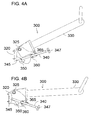
- FIG. 4A and 4B is for the guide device 300 of Fig. 3 the change from the first position to the second position shown.
- the position change is made possible by pivoting (raising) the drawbar 330 relative to the drawbar block 320 about the axis 325 and simultaneous pivoting of the spindle 340 out of the calotte 350.
- connection between the spindle 340 and drawbar 330 is formed by the one or more rubber buffers 365 and the threaded block 360 as described above.
- the threaded block 360 is connected via the rubber buffers 365 to the drawbar 330 and articulated and resiliently mounted.
- the rubber buffers 365 serve as a spring element which holds the spindle in a starting position corresponding to the first position. They allow pivoting of the screw 340 screwed into the threaded block 360.
- the rubber buffer or 365 are deformed during pivoting of the spindle 340.
- the pivoting takes place against the resilient action of the rubber buffer 365.
- This ensures on the one hand that the vibrations generated by the soil compacting device, which are transmitted via the drawbar block 320, the cap 350 and the spindle 340 to the drawbar 330, attenuated by the rubber buffer 365 become.
- the rubber buffer 365 ensures the rubber buffer 365 that the spindle 340 is moved back in the absence of an external force in the starting position and thus the tip 345 of the spindle 340 when returning the drawbar 330 from the second to the first position automatically in the recess provided for the calotte 350 stops.
- Other spring elements, such as additional springs, are not required, resulting in a simplification of the structure of the guide device 300.
- the pivoting of the spindle 340 and thus the release of the tip 345 from the calotte 350 is effected by applying a force to a serving as a transmission element handle 347 of the spindle 340.
- the handle 347 of the spindle 340 for screwing the spindle 340 in serve the threaded block 360.
- the spindle 340 is moved such that its tip 345 releases upward from the calotte 350 and thereby ends the supporting action that holds the drawbar 330 in the first position.
- the spindle 340 is mounted in a slotted guide, which makes it possible to move the spindle 340 linearly, approximately along one of the image plane of the FIG. 4A and 4B pointing out direction.
- the spindle 340 is then released from the calotte 350 by sliding along the slotted guide.
- the displacement can be done against a restoring force, for example, against a spring force of spring elements.
- the drawbar 330 in the in FIG. 4B shown second position can be lowered.
- the drawbar 330 can be held by the spindle 340 in the second position. But it can also be held by other components of the guide device 300 in the second position, for example by a stop or a bolt which penetrates the tiller block 320 in a direction perpendicular to the plane of the drawing entirely and on which the drawbar 330 rests in the second position.
- the tip 345 of the spindle 340 is biased against the bevel above the cap 350. If the drawbar 330 is now again in the first position, i. brought to the original working height, it is raised and moved so long until the tip 345 of the spindle 340, pressed by the resilient mounting of the spindle 340 down, snaps back into the calotte 350.
- the in the FIG. 3 . 4A and 4B shown embodiment allows height adjustment of the drawbar 330 in the first position.
- the height adjustment can be achieved by screwing the spindle 340 into the threaded block 360.
- the further the handle 347 approaches the threaded block 360 by continuous screwing in the steeper the inclination of the drawbar 330 becomes.
- by unscrewing the spindle 340 from the threaded block 360 a flatter working position is produced.
- the angular position between the drawbar 330 and the drawbar block 320 is adjusted by screwing the spindle 340 into the threaded block 360.
- the support element 140 has a height adjustment element, which is suitable for setting an angular position between connecting element 120 and drawbar element 130 and thus for adjusting a distance of the drawbar element 130 from the ground.
- the height adjustment element can, for example, have a rod segment with latching recesses.
- the recesses may be elongated holes. Then, the angular position of the drawbar member 130 is adjusted to the connecting member 120 in the first position by clamping fasteners in one of the recesses of the bar segment.
- the axis formed by the attachment means also serves as the movable connection of the support member 140 with the drawbar member 130 or the connector 120.
- the inclination angle of the drawbar 130 becomes steeper, which corresponds to an upper working position. If the holding element 150 positioned further down, the working position will be further down.
- FIG. 2A show mechanical reversal of the embodiment of FIG. 1A positioning the retaining element 250 closer to the axis 225 towards the working position are moved further upwards and by positioning in the opposite direction further down.
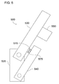
- a tiller element 530 has a first fixing element 570 and a support element 540 has a second fixing element 575. Furthermore, the guide device 500 has a connecting element 520 and a holding element 550.
- the function of the guide device 500 corresponds to that in the FIG. 2A to 2C illustrated embodiment. Therefore, a further detailed description of the interaction of the components is omitted and the description of the FIG. 2A to 2C directed.
- the first fixing member 570 and the second fixing member 575 are disposed on the drawbar member 530 and the support member 540 so as to abut or engage with each other when the drawbar member 530 is in a third position which is above the first position and the support member 540 is pivoted.
- the first and the second fixing element 570, 575 can thereby enter into a fixed connection mediated by fastening means such as screws or rivets, which holds the drawbar element 530 firmly in the third position.
- the fixing elements 570, 575 make it possible to bring the tiller element 530 of the guide device 500 in the third position, which is almost vertical and, for example, for transport or storage of a means of Connecting element 520 with the guide device 500 connected working device particularly suitable. Nevertheless, the fast detachable configuration of the fixing elements 570, 575 ensures rapid return of the drawbar element 530 to the first position, which allows a quick and uncomplicated resumption of a working operation with the working device.
- the first and second fixing members 570, 575 may also be formed as a pair of hooks or latching means that allow the fixation to be released when the support member 540 is swung out.
- the second fixing member 575 may be a tip of the support member 540 when the first fixing member 570 is formed as a dome, which receives the tip of the support member 540 such that a secure connection between the support member 540 and dome arises.
- the second fixing element 575 can also be a ratchet tooth, which engages in the first fixing element 570, eg a dome.
- the ratchet tooth may, for example, be connected to a threaded block when the support element 540 is as in FIG FIG. 3 to 4B is shown formed.
- first and second fixing elements 570, 575 has been described above with reference to the embodiment of FIGS FIG. 2A to 2C described. According to another embodiment, it is possible that the first and the second fixing member 570, 575 on a guide device according to the embodiment of FIG. 1A to 1C are attached. The comments made above then apply analogously.
- the embodiments described with reference to the figures allow rapid, uncomplicated and tool-less change a tiller element for guiding a working device between a first position in which the implement can be guided ergonomically in normal operation, and a second position, which is suitable for driving under obstacles suitable. If, for example, the tiller is to be lowered quickly, it is sufficient to lift it slightly to relieve the spindle. Then the handle of the spindle is pressed down and swung the spindle out of the dome. While the handle of the spindle remains depressed to prevent the spindle from springing back into the starting position, the drawbar is lowered until, supported by an end stop, it assumes the second position.
- tiller If the tiller is now in the first position, i. brought to the original working height, it is raised and moved so long until the tip of the spindle, pressed by the resilient bearing of the spindle down, snaps back into the calotte.
Landscapes
- Engineering & Computer Science (AREA)
- Life Sciences & Earth Sciences (AREA)
- Environmental Sciences (AREA)
- Chemical & Material Sciences (AREA)
- Combustion & Propulsion (AREA)
- Transportation (AREA)
- Mechanical Engineering (AREA)
- Agricultural Machines (AREA)
- Soil Working Implements (AREA)
Applications Claiming Priority (1)
| Application Number | Priority Date | Filing Date | Title |
|---|---|---|---|
| DE102014007559.1A DE102014007559A1 (de) | 2014-05-22 | 2014-05-22 | Höhenverstellbare Führungsvorrichtung für ein Arbeitsgerät |
Publications (3)
| Publication Number | Publication Date |
|---|---|
| EP2957486A2 true EP2957486A2 (fr) | 2015-12-23 |
| EP2957486A3 EP2957486A3 (fr) | 2016-02-10 |
| EP2957486B1 EP2957486B1 (fr) | 2018-01-10 |
Family
ID=53039155
Family Applications (1)
| Application Number | Title | Priority Date | Filing Date |
|---|---|---|---|
| EP15001087.4A Active EP2957486B1 (fr) | 2014-05-22 | 2015-04-15 | Dispositif de guidage réglable en hauteur pour un appareil de travail |
Country Status (3)
| Country | Link |
|---|---|
| EP (1) | EP2957486B1 (fr) |
| CN (1) | CN204803871U (fr) |
| DE (1) | DE102014007559A1 (fr) |
Families Citing this family (2)
| Publication number | Priority date | Publication date | Assignee | Title |
|---|---|---|---|---|
| EP4179150A4 (fr) | 2020-07-07 | 2024-09-04 | Milwaukee Electric Tool Corporation | Compacteur à plaque |
| US12065790B2 (en) | 2020-07-07 | 2024-08-20 | Milwaukee Electric Tool Corporation | Plate compactor |
Family Cites Families (10)
| Publication number | Priority date | Publication date | Assignee | Title |
|---|---|---|---|---|
| US2763492A (en) * | 1952-12-12 | 1956-09-18 | William H Phelps | Reversible handle mounting for a mower |
| US2791437A (en) * | 1953-09-22 | 1957-05-07 | Dille & Mcguire Mfg Co | Lawn mower handle adjustment and safety device |
| US2786694A (en) * | 1955-06-20 | 1957-03-26 | Motor Wheel Corp | Adjustable mounting for handle of lawn mowers |
| US3416417A (en) * | 1966-08-01 | 1968-12-17 | Racine Hydraulics & Machinery | Vibratory compactor |
| US3817547A (en) * | 1973-01-11 | 1974-06-18 | Jacobsen Mfg Co | Lawn mower handle mounting |
| US3791116A (en) * | 1973-05-14 | 1974-02-12 | Deere & Co | Handle support for a walk-behind mower |
| US5842329A (en) * | 1996-10-22 | 1998-12-01 | Deere & Company | Adjustable lawn mower handle mount |
| JP3626329B2 (ja) * | 1997-07-23 | 2005-03-09 | 三笠産業株式会社 | バイブロコンパクターの防振ハンドル |
| SE513650C2 (sv) * | 1999-02-03 | 2000-10-16 | Svedala Compaction Equipment A | Vibratorplatta med ställbart avvibrerat handtag |
| DE102004015588A1 (de) * | 2004-03-01 | 2005-09-22 | Bomag Gmbh | Arbeitsgerät mit schwingungsgedämpftem Führungselement |
-
2014
- 2014-05-22 DE DE102014007559.1A patent/DE102014007559A1/de not_active Ceased
-
2015
- 2015-04-15 EP EP15001087.4A patent/EP2957486B1/fr active Active
- 2015-05-21 CN CN201520350223.0U patent/CN204803871U/zh not_active Expired - Fee Related
Non-Patent Citations (1)
| Title |
|---|
| None |
Also Published As
| Publication number | Publication date |
|---|---|
| EP2957486B1 (fr) | 2018-01-10 |
| CN204803871U (zh) | 2015-11-25 |
| DE102014007559A1 (de) | 2015-11-26 |
| EP2957486A3 (fr) | 2016-02-10 |
Similar Documents
| Publication | Publication Date | Title |
|---|---|---|
| EP2374657B1 (fr) | Accoudoir et poste de commande doté d'un tel accoudoir | |
| DE102013104413C5 (de) | Kniehebelspanner | |
| EP3511201B1 (fr) | Dispositif de réglage destiné au réglage longitidunal d'un siège de véhicule | |
| DE102015012560A1 (de) | Fahrstand für eine Baumaschine und Baumaschine mit einem Fahrstand | |
| EP2980316A1 (fr) | Dispositif d'étanchéification de sol avec amortissement et guidage | |
| EP3153066B1 (fr) | Dispositif de liaison amovible d'un tiroir de meuble guide mobile dans un corps de meuble par une unité de guidage comprenant ladite unité de guidage | |
| EP3453556A1 (fr) | Dispositif comportant un support de base et un porte-outil | |
| EP2998441B1 (fr) | Poste de commande d'une finisseuse de route doté d'une passerelle avec système de verrouillage | |
| DE2750166A1 (de) | Therapeutisches geraet | |
| EP2957486B1 (fr) | Dispositif de guidage réglable en hauteur pour un appareil de travail | |
| EP2947205A1 (fr) | Dispositif de guidage pouvant être bloqué pour un appareil de travail | |
| EP2551173A1 (fr) | Dispositif de fixation pour un entraînement de rangement | |
| DE102007003927B4 (de) | Schwingungsentlasteter Griff | |
| DE202018000726U1 (de) | Höhenverstellbarer Tisch | |
| EP2481527B1 (fr) | Appareil de travail motorisé | |
| DE102014013046A1 (de) | Montagehaltevorrichtung für Formwerkzeuge | |
| EP2994021B1 (fr) | Sommier à lattes avec entraînement par moteur électrique | |
| EP3360728A1 (fr) | Appuie-tête | |
| DE102008025076A1 (de) | Antriebsvorrichtung | |
| DE102020212967B3 (de) | Verriegelungseinrichtung, höhenverstellbarer Tisch mit der Verriegelungseinrichtung, Fahrzeug mit dem höhenverstellbaren Tisch und Verfahren zum Verriegeln des höhenverstellbaren Tischs | |
| DE69714910T2 (de) | Verstellvorrichtung | |
| DE3111920A1 (de) | Arbeitstisch mit hoehenverstellbarer tischplatte | |
| EP3626521B1 (fr) | Dispositif de couverture pour sièges de véhicule | |
| DE102006028899A1 (de) | Fahrzeugsitz mit einem Sitzbereich, einer Rückenlehne und einem Untergestell | |
| DE202021100747U1 (de) | Bohrgeräteständer |
Legal Events
| Date | Code | Title | Description |
|---|---|---|---|
| PUAI | Public reference made under article 153(3) epc to a published international application that has entered the european phase |
Free format text: ORIGINAL CODE: 0009012 |
|
| AK | Designated contracting states |
Kind code of ref document: A2 Designated state(s): AL AT BE BG CH CY CZ DE DK EE ES FI FR GB GR HR HU IE IS IT LI LT LU LV MC MK MT NL NO PL PT RO RS SE SI SK SM TR |
|
| AX | Request for extension of the european patent |
Extension state: BA ME |
|
| PUAL | Search report despatched |
Free format text: ORIGINAL CODE: 0009013 |
|
| AK | Designated contracting states |
Kind code of ref document: A3 Designated state(s): AL AT BE BG CH CY CZ DE DK EE ES FI FR GB GR HR HU IE IS IT LI LT LU LV MC MK MT NL NO PL PT RO RS SE SI SK SM TR |
|
| AX | Request for extension of the european patent |
Extension state: BA ME |
|
| RIC1 | Information provided on ipc code assigned before grant |
Ipc: B62D 49/06 20060101ALI20160106BHEP Ipc: A01D 34/82 20060101ALI20160106BHEP Ipc: B62D 29/00 20060101AFI20160106BHEP |
|
| 17P | Request for examination filed |
Effective date: 20160729 |
|
| RBV | Designated contracting states (corrected) |
Designated state(s): AL AT BE BG CH CY CZ DE DK EE ES FI FR GB GR HR HU IE IS IT LI LT LU LV MC MK MT NL NO PL PT RO RS SE SI SK SM TR |
|
| GRAP | Despatch of communication of intention to grant a patent |
Free format text: ORIGINAL CODE: EPIDOSNIGR1 |
|
| STAA | Information on the status of an ep patent application or granted ep patent |
Free format text: STATUS: GRANT OF PATENT IS INTENDED |
|
| INTG | Intention to grant announced |
Effective date: 20170810 |
|
| GRAS | Grant fee paid |
Free format text: ORIGINAL CODE: EPIDOSNIGR3 |
|
| GRAA | (expected) grant |
Free format text: ORIGINAL CODE: 0009210 |
|
| STAA | Information on the status of an ep patent application or granted ep patent |
Free format text: STATUS: THE PATENT HAS BEEN GRANTED |
|
| AK | Designated contracting states |
Kind code of ref document: B1 Designated state(s): AL AT BE BG CH CY CZ DE DK EE ES FI FR GB GR HR HU IE IS IT LI LT LU LV MC MK MT NL NO PL PT RO RS SE SI SK SM TR |
|
| REG | Reference to a national code |
Ref country code: CH Ref legal event code: EP Ref country code: AT Ref legal event code: REF Ref document number: 962066 Country of ref document: AT Kind code of ref document: T Effective date: 20180115 |
|
| REG | Reference to a national code |
Ref country code: IE Ref legal event code: FG4D Free format text: LANGUAGE OF EP DOCUMENT: GERMAN |
|
| REG | Reference to a national code |
Ref country code: DE Ref legal event code: R096 Ref document number: 502015002784 Country of ref document: DE |
|
| REG | Reference to a national code |
Ref country code: NL Ref legal event code: MP Effective date: 20180110 |
|
| PG25 | Lapsed in a contracting state [announced via postgrant information from national office to epo] |
Ref country code: NL Free format text: LAPSE BECAUSE OF FAILURE TO SUBMIT A TRANSLATION OF THE DESCRIPTION OR TO PAY THE FEE WITHIN THE PRESCRIBED TIME-LIMIT Effective date: 20180110 |
|
| PG25 | Lapsed in a contracting state [announced via postgrant information from national office to epo] |
Ref country code: HR Free format text: LAPSE BECAUSE OF FAILURE TO SUBMIT A TRANSLATION OF THE DESCRIPTION OR TO PAY THE FEE WITHIN THE PRESCRIBED TIME-LIMIT Effective date: 20180110 Ref country code: CY Free format text: LAPSE BECAUSE OF FAILURE TO SUBMIT A TRANSLATION OF THE DESCRIPTION OR TO PAY THE FEE WITHIN THE PRESCRIBED TIME-LIMIT Effective date: 20180110 Ref country code: LT Free format text: LAPSE BECAUSE OF FAILURE TO SUBMIT A TRANSLATION OF THE DESCRIPTION OR TO PAY THE FEE WITHIN THE PRESCRIBED TIME-LIMIT Effective date: 20180110 Ref country code: ES Free format text: LAPSE BECAUSE OF FAILURE TO SUBMIT A TRANSLATION OF THE DESCRIPTION OR TO PAY THE FEE WITHIN THE PRESCRIBED TIME-LIMIT Effective date: 20180110 Ref country code: NO Free format text: LAPSE BECAUSE OF FAILURE TO SUBMIT A TRANSLATION OF THE DESCRIPTION OR TO PAY THE FEE WITHIN THE PRESCRIBED TIME-LIMIT Effective date: 20180410 Ref country code: FI Free format text: LAPSE BECAUSE OF FAILURE TO SUBMIT A TRANSLATION OF THE DESCRIPTION OR TO PAY THE FEE WITHIN THE PRESCRIBED TIME-LIMIT Effective date: 20180110 |
|
| PG25 | Lapsed in a contracting state [announced via postgrant information from national office to epo] |
Ref country code: LV Free format text: LAPSE BECAUSE OF FAILURE TO SUBMIT A TRANSLATION OF THE DESCRIPTION OR TO PAY THE FEE WITHIN THE PRESCRIBED TIME-LIMIT Effective date: 20180110 Ref country code: SE Free format text: LAPSE BECAUSE OF FAILURE TO SUBMIT A TRANSLATION OF THE DESCRIPTION OR TO PAY THE FEE WITHIN THE PRESCRIBED TIME-LIMIT Effective date: 20180110 Ref country code: PL Free format text: LAPSE BECAUSE OF FAILURE TO SUBMIT A TRANSLATION OF THE DESCRIPTION OR TO PAY THE FEE WITHIN THE PRESCRIBED TIME-LIMIT Effective date: 20180110 Ref country code: IS Free format text: LAPSE BECAUSE OF FAILURE TO SUBMIT A TRANSLATION OF THE DESCRIPTION OR TO PAY THE FEE WITHIN THE PRESCRIBED TIME-LIMIT Effective date: 20180510 Ref country code: GR Free format text: LAPSE BECAUSE OF FAILURE TO SUBMIT A TRANSLATION OF THE DESCRIPTION OR TO PAY THE FEE WITHIN THE PRESCRIBED TIME-LIMIT Effective date: 20180411 Ref country code: RS Free format text: LAPSE BECAUSE OF FAILURE TO SUBMIT A TRANSLATION OF THE DESCRIPTION OR TO PAY THE FEE WITHIN THE PRESCRIBED TIME-LIMIT Effective date: 20180110 Ref country code: BG Free format text: LAPSE BECAUSE OF FAILURE TO SUBMIT A TRANSLATION OF THE DESCRIPTION OR TO PAY THE FEE WITHIN THE PRESCRIBED TIME-LIMIT Effective date: 20180410 |
|
| PG25 | Lapsed in a contracting state [announced via postgrant information from national office to epo] |
Ref country code: MT Free format text: LAPSE BECAUSE OF FAILURE TO SUBMIT A TRANSLATION OF THE DESCRIPTION OR TO PAY THE FEE WITHIN THE PRESCRIBED TIME-LIMIT Effective date: 20180110 |
|
| REG | Reference to a national code |
Ref country code: DE Ref legal event code: R097 Ref document number: 502015002784 Country of ref document: DE |
|
| PG25 | Lapsed in a contracting state [announced via postgrant information from national office to epo] |
Ref country code: AL Free format text: LAPSE BECAUSE OF FAILURE TO SUBMIT A TRANSLATION OF THE DESCRIPTION OR TO PAY THE FEE WITHIN THE PRESCRIBED TIME-LIMIT Effective date: 20180110 Ref country code: EE Free format text: LAPSE BECAUSE OF FAILURE TO SUBMIT A TRANSLATION OF THE DESCRIPTION OR TO PAY THE FEE WITHIN THE PRESCRIBED TIME-LIMIT Effective date: 20180110 Ref country code: IT Free format text: LAPSE BECAUSE OF FAILURE TO SUBMIT A TRANSLATION OF THE DESCRIPTION OR TO PAY THE FEE WITHIN THE PRESCRIBED TIME-LIMIT Effective date: 20180110 Ref country code: RO Free format text: LAPSE BECAUSE OF FAILURE TO SUBMIT A TRANSLATION OF THE DESCRIPTION OR TO PAY THE FEE WITHIN THE PRESCRIBED TIME-LIMIT Effective date: 20180110 |
|
| PLBE | No opposition filed within time limit |
Free format text: ORIGINAL CODE: 0009261 |
|
| STAA | Information on the status of an ep patent application or granted ep patent |
Free format text: STATUS: NO OPPOSITION FILED WITHIN TIME LIMIT |
|
| PG25 | Lapsed in a contracting state [announced via postgrant information from national office to epo] |
Ref country code: SM Free format text: LAPSE BECAUSE OF FAILURE TO SUBMIT A TRANSLATION OF THE DESCRIPTION OR TO PAY THE FEE WITHIN THE PRESCRIBED TIME-LIMIT Effective date: 20180110 Ref country code: CZ Free format text: LAPSE BECAUSE OF FAILURE TO SUBMIT A TRANSLATION OF THE DESCRIPTION OR TO PAY THE FEE WITHIN THE PRESCRIBED TIME-LIMIT Effective date: 20180110 Ref country code: MC Free format text: LAPSE BECAUSE OF FAILURE TO SUBMIT A TRANSLATION OF THE DESCRIPTION OR TO PAY THE FEE WITHIN THE PRESCRIBED TIME-LIMIT Effective date: 20180110 Ref country code: DK Free format text: LAPSE BECAUSE OF FAILURE TO SUBMIT A TRANSLATION OF THE DESCRIPTION OR TO PAY THE FEE WITHIN THE PRESCRIBED TIME-LIMIT Effective date: 20180110 Ref country code: SK Free format text: LAPSE BECAUSE OF FAILURE TO SUBMIT A TRANSLATION OF THE DESCRIPTION OR TO PAY THE FEE WITHIN THE PRESCRIBED TIME-LIMIT Effective date: 20180110 |
|
| REG | Reference to a national code |
Ref country code: CH Ref legal event code: PL |
|
| 26N | No opposition filed |
Effective date: 20181011 |
|
| REG | Reference to a national code |
Ref country code: BE Ref legal event code: MM Effective date: 20180430 |
|
| REG | Reference to a national code |
Ref country code: IE Ref legal event code: MM4A |
|
| PG25 | Lapsed in a contracting state [announced via postgrant information from national office to epo] |
Ref country code: LU Free format text: LAPSE BECAUSE OF NON-PAYMENT OF DUE FEES Effective date: 20180415 |
|
| PG25 | Lapsed in a contracting state [announced via postgrant information from national office to epo] |
Ref country code: LI Free format text: LAPSE BECAUSE OF NON-PAYMENT OF DUE FEES Effective date: 20180430 Ref country code: BE Free format text: LAPSE BECAUSE OF NON-PAYMENT OF DUE FEES Effective date: 20180430 Ref country code: CH Free format text: LAPSE BECAUSE OF NON-PAYMENT OF DUE FEES Effective date: 20180430 Ref country code: SI Free format text: LAPSE BECAUSE OF FAILURE TO SUBMIT A TRANSLATION OF THE DESCRIPTION OR TO PAY THE FEE WITHIN THE PRESCRIBED TIME-LIMIT Effective date: 20180110 |
|
| PG25 | Lapsed in a contracting state [announced via postgrant information from national office to epo] |
Ref country code: FR Free format text: LAPSE BECAUSE OF NON-PAYMENT OF DUE FEES Effective date: 20180430 Ref country code: IE Free format text: LAPSE BECAUSE OF NON-PAYMENT OF DUE FEES Effective date: 20180415 |
|
| GBPC | Gb: european patent ceased through non-payment of renewal fee |
Effective date: 20190415 |
|
| PG25 | Lapsed in a contracting state [announced via postgrant information from national office to epo] |
Ref country code: GB Free format text: LAPSE BECAUSE OF NON-PAYMENT OF DUE FEES Effective date: 20190415 |
|
| PG25 | Lapsed in a contracting state [announced via postgrant information from national office to epo] |
Ref country code: TR Free format text: LAPSE BECAUSE OF FAILURE TO SUBMIT A TRANSLATION OF THE DESCRIPTION OR TO PAY THE FEE WITHIN THE PRESCRIBED TIME-LIMIT Effective date: 20180110 |
|
| PG25 | Lapsed in a contracting state [announced via postgrant information from national office to epo] |
Ref country code: PT Free format text: LAPSE BECAUSE OF FAILURE TO SUBMIT A TRANSLATION OF THE DESCRIPTION OR TO PAY THE FEE WITHIN THE PRESCRIBED TIME-LIMIT Effective date: 20180110 |
|
| PG25 | Lapsed in a contracting state [announced via postgrant information from national office to epo] |
Ref country code: MK Free format text: LAPSE BECAUSE OF NON-PAYMENT OF DUE FEES Effective date: 20180110 Ref country code: HU Free format text: LAPSE BECAUSE OF FAILURE TO SUBMIT A TRANSLATION OF THE DESCRIPTION OR TO PAY THE FEE WITHIN THE PRESCRIBED TIME-LIMIT; INVALID AB INITIO Effective date: 20150415 |
|
| REG | Reference to a national code |
Ref country code: AT Ref legal event code: MM01 Ref document number: 962066 Country of ref document: AT Kind code of ref document: T Effective date: 20200415 |
|
| PG25 | Lapsed in a contracting state [announced via postgrant information from national office to epo] |
Ref country code: AT Free format text: LAPSE BECAUSE OF NON-PAYMENT OF DUE FEES Effective date: 20200415 |
|
| PGFP | Annual fee paid to national office [announced via postgrant information from national office to epo] |
Ref country code: DE Payment date: 20250417 Year of fee payment: 11 |