EP2957788A1 - Avion capable de vol stationnaire avec limiteur de couple - Google Patents
Avion capable de vol stationnaire avec limiteur de couple Download PDFInfo
- Publication number
- EP2957788A1 EP2957788A1 EP14425078.4A EP14425078A EP2957788A1 EP 2957788 A1 EP2957788 A1 EP 2957788A1 EP 14425078 A EP14425078 A EP 14425078A EP 2957788 A1 EP2957788 A1 EP 2957788A1
- Authority
- EP
- European Patent Office
- Prior art keywords
- axis
- stop
- drive
- aircraft according
- seat
- Prior art date
- Legal status (The legal status is an assumption and is not a legal conclusion. Google has not performed a legal analysis and makes no representation as to the accuracy of the status listed.)
- Withdrawn
Links
- 230000005540 biological transmission Effects 0.000 claims abstract description 25
- 239000000523 sample Substances 0.000 claims description 4
- 238000004891 communication Methods 0.000 claims description 2
- 230000001419 dependent effect Effects 0.000 claims description 2
- 239000003638 chemical reducing agent Substances 0.000 description 4
- 238000012423 maintenance Methods 0.000 description 3
- 230000002035 prolonged effect Effects 0.000 description 3
- 230000002547 anomalous effect Effects 0.000 description 2
- 238000013459 approach Methods 0.000 description 2
- 238000010438 heat treatment Methods 0.000 description 2
- 238000004804 winding Methods 0.000 description 2
- RZVHIXYEVGDQDX-UHFFFAOYSA-N 9,10-anthraquinone Chemical compound C1=CC=C2C(=O)C3=CC=CC=C3C(=O)C2=C1 RZVHIXYEVGDQDX-UHFFFAOYSA-N 0.000 description 1
- 230000000694 effects Effects 0.000 description 1
- 239000010687 lubricating oil Substances 0.000 description 1
- 238000000034 method Methods 0.000 description 1
- 238000012986 modification Methods 0.000 description 1
- 230000004048 modification Effects 0.000 description 1
- 230000000737 periodic effect Effects 0.000 description 1
- 230000011664 signaling Effects 0.000 description 1
- 238000012360 testing method Methods 0.000 description 1
Images


Classifications
-
- F—MECHANICAL ENGINEERING; LIGHTING; HEATING; WEAPONS; BLASTING
- F16—ENGINEERING ELEMENTS AND UNITS; GENERAL MEASURES FOR PRODUCING AND MAINTAINING EFFECTIVE FUNCTIONING OF MACHINES OR INSTALLATIONS; THERMAL INSULATION IN GENERAL
- F16D—COUPLINGS FOR TRANSMITTING ROTATION; CLUTCHES; BRAKES
- F16D7/00—Slip couplings, e.g. slipping on overload, for absorbing shock
- F16D7/04—Slip couplings, e.g. slipping on overload, for absorbing shock of the ratchet type
- F16D7/06—Slip couplings, e.g. slipping on overload, for absorbing shock of the ratchet type with intermediate balls or rollers
- F16D7/10—Slip couplings, e.g. slipping on overload, for absorbing shock of the ratchet type with intermediate balls or rollers moving radially between engagement and disengagement
-
- B—PERFORMING OPERATIONS; TRANSPORTING
- B66—HOISTING; LIFTING; HAULING
- B66D—CAPSTANS; WINCHES; TACKLES, e.g. PULLEY BLOCKS; HOISTS
- B66D1/00—Rope, cable, or chain winding mechanisms; Capstans
- B66D1/54—Safety gear
- B66D1/58—Safety gear responsive to excess of load
-
- B—PERFORMING OPERATIONS; TRANSPORTING
- B66—HOISTING; LIFTING; HAULING
- B66D—CAPSTANS; WINCHES; TACKLES, e.g. PULLEY BLOCKS; HOISTS
- B66D3/00—Portable or mobile lifting or hauling appliances
- B66D3/18—Power-operated hoists
- B66D3/20—Power-operated hoists with driving motor, e.g. electric motor, and drum or barrel contained in a common housing
- B66D3/22—Power-operated hoists with driving motor, e.g. electric motor, and drum or barrel contained in a common housing with variable-speed gearings between driving motor and drum or barrel
-
- F—MECHANICAL ENGINEERING; LIGHTING; HEATING; WEAPONS; BLASTING
- F16—ENGINEERING ELEMENTS AND UNITS; GENERAL MEASURES FOR PRODUCING AND MAINTAINING EFFECTIVE FUNCTIONING OF MACHINES OR INSTALLATIONS; THERMAL INSULATION IN GENERAL
- F16D—COUPLINGS FOR TRANSMITTING ROTATION; CLUTCHES; BRAKES
- F16D43/00—Automatic clutches
- F16D43/02—Automatic clutches actuated entirely mechanically
- F16D43/20—Automatic clutches actuated entirely mechanically controlled by torque, e.g. overload-release clutches, slip-clutches with means by which torque varies the clutching pressure
- F16D43/202—Automatic clutches actuated entirely mechanically controlled by torque, e.g. overload-release clutches, slip-clutches with means by which torque varies the clutching pressure of the ratchet type
- F16D43/204—Automatic clutches actuated entirely mechanically controlled by torque, e.g. overload-release clutches, slip-clutches with means by which torque varies the clutching pressure of the ratchet type with intermediate balls or rollers
- F16D43/208—Automatic clutches actuated entirely mechanically controlled by torque, e.g. overload-release clutches, slip-clutches with means by which torque varies the clutching pressure of the ratchet type with intermediate balls or rollers moving radially between engagement and disengagement
-
- B—PERFORMING OPERATIONS; TRANSPORTING
- B64—AIRCRAFT; AVIATION; COSMONAUTICS
- B64D—EQUIPMENT FOR FITTING IN OR TO AIRCRAFT; FLIGHT SUITS; PARACHUTES; ARRANGEMENT OR MOUNTING OF POWER PLANTS OR PROPULSION TRANSMISSIONS IN AIRCRAFT
- B64D1/00—Dropping, ejecting, releasing or receiving articles, liquids, or the like, in flight
- B64D1/22—Taking-up articles from earth's surface
Definitions
- the present invention relates to an aircraft capable of hovering, in particular a helicopter or a convertiplane.
- the helicopter and convertiplane are examples of such aircraft.
- Aircraft capable of hovering are used advantageously for saving people or recovering objects in emergency situations and/or in difficult to access places, for example, saving shipwreck survivors at sea.
- the salvage operation takes place using a drum carried by a fixed structure of the aircraft and a basket hanging from a cable wound/unwound from the drum and containing a load.
- the aircraft comprises a motor and a reducer interposed between the drum and the motor in order to provide the drum with the correct drive torque and angular speed.
- the tension on the cable generates resistance torque on the drum in the opposite direction to the drive torque.
- the aircraft further comprises a drive torque limiting unit, which is interposed between the reducer and the drum and able to prevent excessive torque being transmitted to the drum and, consequently, to the cable and the load.
- the function of the limiting unit is:
- the limiting unit comprises a clutch formed by:
- the clutch transmits drive torque between the motor and the drum when the tension on the cable is less than or equal to the operating threshold value.
- the clutch prevents the transmission of drive torque between the motor and the drum when the tension on the cable - and, consequently, the resistance torque on the second shaft - is greater than the operating threshold value, due to the slippage between the first set of discs and the second set of discs.
- the limiting unit comprising a clutch of the above-described type is characterized by an operating threshold value that varies according to external factors that are difficult to control such as, for example, the operating temperature of the reducer, the type of lubricating oil used or the clutch adjustment and testing methods.
- the clutch of the above-described limiting unit of known type is subject to wear and heating up in the case of prolonged operation, thereby resulting in the need to periodical perform drum maintenance and/or overhaul operations.
- the above-described limiting unit of known type is unable to signal whether or not torque is being transmitted from the motor to the drum.
- JP-A-2000247296 describes a method of limiting the torque for a helicopter.
- the object of the present invention is to provide an aircraft capable of hovering that enables at least one of the above-stated needs to be satisfied in a simple and inexpensive manner.
- an aircraft capable of hovering comprising: a first drive member; a second member suitable for handling a load; and a transmission unit suitable for connecting said first drive member to said second member in order to transmit, in use, drive torque to said second member; said transmission unit in turn comprising: a first element rotating around an axis and operatively connected to said first drive member; and a second element rotating around said axis and operatively connected to said second member and subjected, in use, to resistance torque in the opposite direction to said drive torque and having a value associated with the weight of said load; said aircraft comprising at least one limiting unit of said drive torque transmitted, in use, from said first member to said second member; said limiting unit being interposed between said first element and said second element; said limiting unit of said drive torque comprising at least one stop element movable, according to the magnitude of said resistance torque and transversely to said axis, between: a first drive position, in which it makes said first
- said limiting unit also comprises a third member integrally rotating with said second member around said axis; said stop element being rotatable around said axis integrally with said third member and radially moveable along said axis with respect to said third member between said first drive position and second stop position.
- said third member comprises at least one groove engaged by said stop element and inside which said stop element may slide between said first drive position and second stop position radially to said axis.
- Said first element comprises at least one first seat and said second element comprises at least one second seat; said first seat and second seat being open towards and in communication with said groove; said stop element engaging said first seat and said groove, so as to make said first element and said second element angularly integral with respect to said axis, when said stop element is in said first drive position; said stop element engaging said groove and said second seat and leaving said first seat empty, so as to make said first element and said second element angularly free from each other with respect to said axis, when said stop element is in said second stop position.
- said limiting unit further comprises a fourth element, annular and movable parallel to said axis due to the movement, in use, of said stop element between said first drive position and said second stop position; said stop element being axially interposed between said third element and said fourth element along said axis.
- Said fourth element is movable in a direction parallel to said axis, between:
- Said fourth element further comprises a tapered stop surface with respect to said axis, facing said stop element and cooperating with said stop element.
- the aircraft comprises a plurality of said stop elements, a plurality of said grooves and a plurality of said first seats, which are arranged angularly spaced out with respect to said axis.
- the aircraft comprises elastic means able to elastically push said stop element towards said first drive position.
- Said elastic means are configured to exert an elastic load on said stop element having a component parallel to said axis.
- the preloading of said elastic means is selectively adjustable, so as to vary the value of said threshold value; said aircraft comprising a ring nut that may be screwed onto one of said first member and second member; said ring nut cooperating with said elastic means on the opposite side of said fourth member.
- said elastic means cooperate with said fourth element on the opposite side of said stop element, going along said axis, so as to axially lock the stop element.
- Said first element, second element and third element extend coaxially to said axis and said third element is interposed between said first element and second element in a radial direction to said axis.
- the aircraft comprises sensor means configured to detect if said stop element is in the drive or stop position.
- said sensor means comprise a probe housed inside a seat defined by said second element and open towards said fourth element.
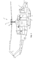
- reference numeral 1 indicates an aircraft capable of hovering, in particular a helicopter, essentially comprising a fuselage 2, a main rotor 3 positioned on the top of the fuselage 2 and rotating around an axis A, and a tail rotor 4 positioned at one end of the fuselage 2 and rotating around its own axis transversely to axis A.
- the helicopter 1 further comprises a hook 6 that may be connected to a basket (not shown) containing a load and able to move in a substantially vertical direction H, so as to cause the raising or lowering of the basket.
- the helicopter 1 further comprises ( Figure 2 ):
- the drum 13 When the motor 11 is working, the drum 13 is subjected to drive torque Cm and resistance torque Cr.
- the resistance torque Cr is substantially equal to the product of the tension on the cable 14 and the radius of the drum 13.
- the tension on the cable 14 is substantially equal to the weight of the basket and the inertial forces acting on the basket.
- axis B is orthogonal to direction H.
- the helicopter 1 further comprises:
- the limiter 9 is configured to:
- the transmission unit 8 comprises the limiter 9.
- the limiter 9 is functionally interposed between the shaft 12 and the drum 13.
- the transmission unit 8 is a reducer, namely it is configured to:
- the transmission unit 8 comprises, in the direction from the shaft 12 towards the drum 13 ( Figure 2 ):
- the transmission unit 8 further comprises:
- the transmission unit 8 comprises:
- shaft 19 houses shaft 12 coaxially to axis B.
- shaft 19 rotates around axis B integrally with the drum 13.
- the transmission unit 8 comprises ( Figure 2 ):
- axis E is eccentric with respect to axis B and is parallel to axes B, C and D.
- the limiter 9 comprises a plurality of stop elements 35, each movable transversely to axis D, according to the magnitude of the resistance torque Cr, between:
- stop elements 35 may be moved radially to axis D between the respective drive and stop positions.
- the stop elements 35 are spheres.
- the limiter 9 essentially comprises:
- shaft 17 comprises:
- portion 33 radially projects from axis D with respect to portions 31 and 32.
- Portion 33 ( Figures 5 and 6 ) of shaft 17 is delimitated, on the opposite side from axis D, by a surface 44 defining a plurality of seats 45, four in the case shown.
- the seats 45 are open on the side radially opposite axis D.
- the seats 45 are shaped so as to be able to accept, at least partially, the respective stop elements 35.
- the seats 45 are delimited by respective spherical surface portions.
- the seats 45 are angularly equidistanced from each other with respect to axis D.
- Ring 41 is interposed between the surface 44 of shaft 17 and the wheel 40, going in a radial direction from axis D.
- Ring 41 defines a plurality of grooves 42, four in the case shown, open along respective radial directions to axis D and engaged by respective stop elements 35.
- the grooves 42 have micro-geometric dimensions.
- Ring 41 further comprises:
- the wheel 40 essentially comprises:
- the transmission unit 3 further comprises:
- the bearing 72 is locked on shaft 17 in a position axially interposed between surface 44 and set of gear teeth 23.
- the boss 39 of the wheel 40 is delimited, in the radially inner direction to axis D, by a surface 48.
- Surface 48 defines a groove 49 and is separated from surface 44 by a radial clearance.
- surface 49 has a shape associated with the form of the stop elements 35.
- the groove 49 is delimited, in a section orthogonal to axis D, by a spherical surface portion ( Figures 3 and 4 ).
- the wheel 40 is set angularly to ring 41 by a plurality of pins 78 (only two of which are visible in Figures 3 and 4 ), which extend parallel to axis D, are angularly equidistant with respect to axis D and are housed in respective holes 79 passing through the boss 39 in a pass-through manner with respect to direction D.
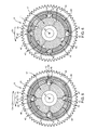
- the stop elements 35 When they are arranged in the respective drive positions ( Figures 3 and 5 ), the stop elements 35 occupy the respective seats 45 and the respective grooves 42, thus making shaft 17 and the set formed by ring 41 and wheel 40 angularly integral with each other with respect to axis D. In these respective drive positions, the stop elements 35 leave groove 49 free.
- the limiter 9 further comprises ( Figures 3 to 6 ):
- ring 55 dragged by friction around axis D by the wheel 40 and by the stop elements 35 is angularly movable with respect to shaft 17 with reference to axis D.
- the internal diameter of ring 55 is greater than the eternal diameter of shaft 17.
- Ring 55 is axially free in the direction parallel to axis D.
- ring 55 may move parallel to axis D between:
- the springs 56 exert an elastic load on ring 55, directed parallel to axis D and towards the first position.
- the preloading of the springs 56 defines the threshold value of the resistance torque Cr, above which the limiter 9 prevents the transmission of drive torque Cm from the motor 11 to the drum 13.
- ring 55 partially obstructs access to groove 49 in a radial direction to axis D when the ring 55 is arranged in the first position ( Figure 4 ).
- ring 55 leaves free access to groove 49 in the radial direction to axis D when ring 55 is arranged in the first position.
- the ring nut 57 allows varying the preloading of the springs 56 and, consequently, the threshold value for the resistance torque Cr.
- Ring 55 is delimited, in the direction parallel to axis D, by:
- Ring 55 further comprises a surface 62 adjacent to surface 60, which makes contact with the stop elements 35.
- Surface 62 is tapered with respect to axis D, going in a radial direction to axis D and towards axis D.
- surface 62 converges towards axis D, in the direction from surface 60 towards surface 61.
- surface 62 has a truncated-cone shape.
- the springs 56 are of the cup type, each one comprising one or more elastic washers coaxial to axis D.
- the limiter 9 comprises a sensor 80 configured to detect if the stop elements 35 are in the respective stop positions or in the respective drive positions.
- the senor 80 is configured to detect the position of ring 55 in a direction parallel to axis D, and consequently detect if the stop elements 35 are in the respective stop positions or in the respective drive positions.
- the senor 80 comprises a probe 82 housed inside a pass-through seat 81 defined by portion 47 of the wheel 40.
- Seat 81 is pass-through in a radial direction to axis D.
- Seat 81 is arranged next to ring 55 and is open towards ring 55 on the side of axis D, such that the probe 82 is sensitive to the position of ring 55 parallel to axis D.
- the limiter 9 allows the transmission of drive torque Cm from the motor 11 to the drum 13, thus causing the winding/unwinding of cable 14 on the drum 13 and the raising/lowering of the hook 6 and the basket along direction H.
- the motor 11 is operated and drives shaft 12 in rotation around axis B, which in turn drives shaft 17 in rotation around axis C and shaft 18 around axis D, via the sets of gear teeth 20 and 21; 22 and 23.
- the stop elements 35 remain in the respective drive positions.
- stop elements 35 partially engage the seats 45 of shaft 18 and partially engage the grooves 42 of ring 41, making shaft 18 and ring 41 angularly integral with each other with respect to axis D.
- stop elements 35 make the shaft 18 and the wheel 40 integral with each other, which rotate around axis D.
- the stop elements 35 are axially held along direction D from ring 55, which is, in turn, elastically pushed towards the stop elements 35 by the springs 56.
- the rotation of the wheel 40 around axis D causes, via the sets of gear teeth 24 and 25, the rotation of shaft 18 around axis E and, via the sets of gear teeth 26 and 27, the rotation of shaft 19 around axis B.
- the rotation of shaft 19 causes the rotation of the drum 13 around axis B and, therefore, the unwinding/winding of the cable 14 on the drum 13 and the lowering/raising of the hook 6 and the load along direction H.
- the limiter 9 interrupts the transmission of driving force from shaft 17 to the wheel 40 and, therefore, from the motor 11 to the drum 13.
- stop elements 35 remain held inside grooves 42 of ring 41, while the seats 45 advance the respective stop elements 35 angularly to axis D, until the seats 45 are angularly staggered by the respective stop elements 35 ( Figure 4 ).
- the stop elements 35 remain integral with ring 41 and slide in the respective grooves 42 in a radial direction to axis D and on a wall facing axis D, until they become arranged in the respective stop positions shown in Figures 4 and 6 .
- the stop elements 35 occupy, in the respective stop positions, the respective grooves 42 and groove 49 defined by the wheel 40. Otherwise, the stop elements 35 leave the seats 45 of shaft 17 free.
- shaft 17 continues to turn around axis D under the action of the motor 11, while ring 41 and the wheel 40 remain stationary with respect to axis D.
- the limiter 9 ( Figure 6 ) thus prevents the transmission of drive torque Cm to the drum 13 and to the cable 14.
- the sensor 80 detects the position of ring 55 parallel to axis D and, therefore, detects whether the stop elements 35 are in the respective drive or stop positions. In consequence, the sensor 80 detects whether or not transmission of drive torque Cm from the motor 11 to the drum 13 has been interrupted.
- the stop elements 35 return to the respective drive positions, in which they again make the shaft 17 and the set formed by wheel 40 and ring 41 integral with respect to axis D and where the motor 11 thus transmits drive torque Cm to the drum 13 again in order to raise/lower the hook and the load parallel to direction H.
- stop elements 35 of the limiter 9 are arranged:
- the limiter 9 couples the motor 11 and the drum 13 when the resistance torque Cr is less than or equal to the threshold value.
- the limiter 9 prevents the transmission of driving force from the motor 11 to the drum 13, when resistance torque Cr is greater than the threshold value.
- the limiter 9 enables maintaining the threshold value for the resistance torque Cr, above which the motor 11 is uncoupled from the drum 13, in a more precise and constant manner over time with respect to the known solutions illustrated in the introductory part of the description.
- the high precision and repeatability of the threshold value maintained by the limiter 9 also enables ensuring that the tension on the cable 14 is kept at values slightly below the breaking load of the cable 14 when the resistance torque Cr is less than or equal to the threshold value.
- the high precision and repeatability of the threshold value maintained by the limiter 9 also enables automatically restoring drive transmission from the motor 11 to the drum 13, when the overload on the cable 14 is removed.
- the limiter 9 is substantially free of wear and prolonged heating effects, and so does not require particularly onerous periodic maintenance and/or overhaul operations.
- the senor 80 allows detecting, in real time and with high reliability, whether or not driving force is transmitted from the motor 11 to the drum 13, based on the position of the ring 55 along axis D.
- the aircraft could be a convertiplane.
- stop elements 35 might not be spheres; for example, they could be cylinders or rollers.
Landscapes
- Engineering & Computer Science (AREA)
- General Engineering & Computer Science (AREA)
- Mechanical Engineering (AREA)
- Transmission Devices (AREA)
Priority Applications (1)
| Application Number | Priority Date | Filing Date | Title |
|---|---|---|---|
| EP14425078.4A EP2957788A1 (fr) | 2014-06-20 | 2014-06-20 | Avion capable de vol stationnaire avec limiteur de couple |
Applications Claiming Priority (1)
| Application Number | Priority Date | Filing Date | Title |
|---|---|---|---|
| EP14425078.4A EP2957788A1 (fr) | 2014-06-20 | 2014-06-20 | Avion capable de vol stationnaire avec limiteur de couple |
Publications (1)
| Publication Number | Publication Date |
|---|---|
| EP2957788A1 true EP2957788A1 (fr) | 2015-12-23 |
Family
ID=51357888
Family Applications (1)
| Application Number | Title | Priority Date | Filing Date |
|---|---|---|---|
| EP14425078.4A Withdrawn EP2957788A1 (fr) | 2014-06-20 | 2014-06-20 | Avion capable de vol stationnaire avec limiteur de couple |
Country Status (1)
| Country | Link |
|---|---|
| EP (1) | EP2957788A1 (fr) |
Cited By (5)
| Publication number | Priority date | Publication date | Assignee | Title |
|---|---|---|---|---|
| CN109678075A (zh) * | 2019-01-15 | 2019-04-26 | 杭州洛基机械制造有限公司 | 一种用于电动绞车的扭矩限制器连接结构 |
| WO2022221751A1 (fr) | 2021-04-16 | 2022-10-20 | Breeze-Eastern Llc | Mise en œuvre de frein d'arrêt d'urgence pour des systèmes de levage |
| US20240199389A1 (en) * | 2022-12-16 | 2024-06-20 | Reel | Method for protecting a lifting member against an overload and device implementing this method |
| US20260029028A1 (en) * | 2024-07-23 | 2026-01-29 | Svm Schultz Verwaltungs-Gmbh & Co. Kg | Overload Clutch Arrangement |
| US12617657B2 (en) * | 2022-12-16 | 2026-05-05 | Reel | Method for protecting a lifting member against an overload and device implementing this method |
Citations (10)
| Publication number | Priority date | Publication date | Assignee | Title |
|---|---|---|---|---|
| US2353562A (en) * | 1941-08-15 | 1944-07-11 | Stone J & Co Ltd | Cable tensioning and releasing means |
| US3358968A (en) * | 1966-10-27 | 1967-12-19 | Breeze Corp | Continuous loop variable penetration winch |
| US3770086A (en) * | 1971-04-12 | 1973-11-06 | Eaton Corp | Hoist having yielding means for load limiting |
| US4041729A (en) * | 1975-03-14 | 1977-08-16 | Otto Bilz Werkzeugfabrik | Overland coupling device |
| US4255946A (en) * | 1979-03-30 | 1981-03-17 | Hansen Quinten A | Torque overload sensing device |
| US4273227A (en) * | 1978-12-04 | 1981-06-16 | Grey John C | Torque-transmitting devices |
| US4311224A (en) * | 1978-08-24 | 1982-01-19 | Kabushiki Kaisha Sankyo Seisakujo | Torque limiter |
| US4628455A (en) | 1983-05-06 | 1986-12-09 | Sperry Corporation | Cross axis torque limiter for helicopter autopilot |
| EP0303121A1 (fr) * | 1987-08-14 | 1989-02-15 | British Autogard Limited | Embrayage limiteur de couple |
| JP2000247296A (ja) | 1999-02-26 | 2000-09-12 | Commuter Helicopter Senshin Gijutsu Kenkyusho:Kk | トルク制限方法および回転翼機の高度保持装置 |
-
2014
- 2014-06-20 EP EP14425078.4A patent/EP2957788A1/fr not_active Withdrawn
Patent Citations (10)
| Publication number | Priority date | Publication date | Assignee | Title |
|---|---|---|---|---|
| US2353562A (en) * | 1941-08-15 | 1944-07-11 | Stone J & Co Ltd | Cable tensioning and releasing means |
| US3358968A (en) * | 1966-10-27 | 1967-12-19 | Breeze Corp | Continuous loop variable penetration winch |
| US3770086A (en) * | 1971-04-12 | 1973-11-06 | Eaton Corp | Hoist having yielding means for load limiting |
| US4041729A (en) * | 1975-03-14 | 1977-08-16 | Otto Bilz Werkzeugfabrik | Overland coupling device |
| US4311224A (en) * | 1978-08-24 | 1982-01-19 | Kabushiki Kaisha Sankyo Seisakujo | Torque limiter |
| US4273227A (en) * | 1978-12-04 | 1981-06-16 | Grey John C | Torque-transmitting devices |
| US4255946A (en) * | 1979-03-30 | 1981-03-17 | Hansen Quinten A | Torque overload sensing device |
| US4628455A (en) | 1983-05-06 | 1986-12-09 | Sperry Corporation | Cross axis torque limiter for helicopter autopilot |
| EP0303121A1 (fr) * | 1987-08-14 | 1989-02-15 | British Autogard Limited | Embrayage limiteur de couple |
| JP2000247296A (ja) | 1999-02-26 | 2000-09-12 | Commuter Helicopter Senshin Gijutsu Kenkyusho:Kk | トルク制限方法および回転翼機の高度保持装置 |
Cited By (6)
| Publication number | Priority date | Publication date | Assignee | Title |
|---|---|---|---|---|
| CN109678075A (zh) * | 2019-01-15 | 2019-04-26 | 杭州洛基机械制造有限公司 | 一种用于电动绞车的扭矩限制器连接结构 |
| WO2022221751A1 (fr) | 2021-04-16 | 2022-10-20 | Breeze-Eastern Llc | Mise en œuvre de frein d'arrêt d'urgence pour des systèmes de levage |
| EP4323303A4 (fr) * | 2021-04-16 | 2025-02-26 | Breeze-Eastern LLC | Mise en ?uvre de frein d'arrêt d'urgence pour des systèmes de levage |
| US20240199389A1 (en) * | 2022-12-16 | 2024-06-20 | Reel | Method for protecting a lifting member against an overload and device implementing this method |
| US12617657B2 (en) * | 2022-12-16 | 2026-05-05 | Reel | Method for protecting a lifting member against an overload and device implementing this method |
| US20260029028A1 (en) * | 2024-07-23 | 2026-01-29 | Svm Schultz Verwaltungs-Gmbh & Co. Kg | Overload Clutch Arrangement |
Similar Documents
| Publication | Publication Date | Title |
|---|---|---|
| EP3753850B1 (fr) | Rotor anticouple pour hélicoptère | |
| EP2957788A1 (fr) | Avion capable de vol stationnaire avec limiteur de couple | |
| EP3252330A1 (fr) | Embrayage pour un treuil ou dispositif de levage | |
| EP3360834B1 (fr) | Ensemble d'anneaux pour régulateur d'ascenseur, régulateur et système d'ascenseur | |
| US10759631B2 (en) | Remote triggering device, overspeed governor assembly and elevator | |
| EP3150537B1 (fr) | Régulateur de survitesse d'un ascenseur | |
| US5222578A (en) | Safety brake | |
| CN113682987B (zh) | 一种起重机作业安全监测装置 | |
| US20140135132A1 (en) | Non-chattering ball detent torque limiter | |
| GB2106855A (en) | A safety device | |
| US9039538B2 (en) | Non-chattering ball detent torque limiter | |
| CN111942573B (zh) | 具有可脱开的输出杆的致动器 | |
| EP3715657B1 (fr) | Ensemble accouplement à protection de surcharge pour treuil | |
| EP3753849B1 (fr) | Rotor anticouple pour hélicoptère | |
| US3643770A (en) | Overload torque clutch | |
| CN203939893U (zh) | 可以释放过载扭矩的回转装置 | |
| SE542512C2 (sv) | Säkerhetsbroms vid hiss | |
| CN105435381A (zh) | 一种自动控制匀速下降装置 | |
| CN111792488A (zh) | 一种电梯限速装置 | |
| KR102341958B1 (ko) | 과속 방지 기능을 갖는 토크 제한기 | |
| CN111792524A (zh) | 一种失速保护起重机 | |
| EP3805138B1 (fr) | Frein centrifuge désaccouplable pour équipement élévateur | |
| RU2366605C1 (ru) | Грузозахватное приспособление с ограничителем грузоподъемности | |
| DE1210533B (de) | Geschwindigkeitsbegrenzer fuer Aufzuege | |
| EP2840053A1 (fr) | Dispositif de surveillance pour une cabine d'ascenseur |
Legal Events
| Date | Code | Title | Description |
|---|---|---|---|
| PUAI | Public reference made under article 153(3) epc to a published international application that has entered the european phase |
Free format text: ORIGINAL CODE: 0009012 |
|
| AK | Designated contracting states |
Kind code of ref document: A1 Designated state(s): AL AT BE BG CH CY CZ DE DK EE ES FI FR GB GR HR HU IE IS IT LI LT LU LV MC MK MT NL NO PL PT RO RS SE SI SK SM TR |
|
| AX | Request for extension of the european patent |
Extension state: BA ME |
|
| STAA | Information on the status of an ep patent application or granted ep patent |
Free format text: STATUS: THE APPLICATION IS DEEMED TO BE WITHDRAWN |
|
| 18D | Application deemed to be withdrawn |
Effective date: 20160624 |