EP2957791A1 - Stossdämpfer - Google Patents
Stossdämpfer Download PDFInfo
- Publication number
- EP2957791A1 EP2957791A1 EP15172128.9A EP15172128A EP2957791A1 EP 2957791 A1 EP2957791 A1 EP 2957791A1 EP 15172128 A EP15172128 A EP 15172128A EP 2957791 A1 EP2957791 A1 EP 2957791A1
- Authority
- EP
- European Patent Office
- Prior art keywords
- inner tube
- piston rod
- shock absorber
- tube
- outer tube
- Prior art date
- Legal status (The legal status is an assumption and is not a legal conclusion. Google has not performed a legal analysis and makes no representation as to the accuracy of the status listed.)
- Granted
Links
Images

Classifications
-
- F—MECHANICAL ENGINEERING; LIGHTING; HEATING; WEAPONS; BLASTING
- F16—ENGINEERING ELEMENTS AND UNITS; GENERAL MEASURES FOR PRODUCING AND MAINTAINING EFFECTIVE FUNCTIONING OF MACHINES OR INSTALLATIONS; THERMAL INSULATION IN GENERAL
- F16F—SPRINGS; SHOCK-ABSORBERS; MEANS FOR DAMPING VIBRATION
- F16F13/00—Units comprising springs of the non-fluid type as well as vibration-dampers, shock-absorbers, or fluid springs
- F16F13/005—Units comprising springs of the non-fluid type as well as vibration-dampers, shock-absorbers, or fluid springs comprising both a wound spring and a damper, e.g. a friction damper
- F16F13/007—Units comprising springs of the non-fluid type as well as vibration-dampers, shock-absorbers, or fluid springs comprising both a wound spring and a damper, e.g. a friction damper the damper being a fluid damper
-
- F—MECHANICAL ENGINEERING; LIGHTING; HEATING; WEAPONS; BLASTING
- F16—ENGINEERING ELEMENTS AND UNITS; GENERAL MEASURES FOR PRODUCING AND MAINTAINING EFFECTIVE FUNCTIONING OF MACHINES OR INSTALLATIONS; THERMAL INSULATION IN GENERAL
- F16F—SPRINGS; SHOCK-ABSORBERS; MEANS FOR DAMPING VIBRATION
- F16F9/00—Springs, vibration-dampers, shock-absorbers, or similarly-constructed movement-dampers using a fluid or the equivalent as damping medium
- F16F9/32—Details
- F16F9/44—Means on or in the damper for manual or non-automatic adjustment; such means combined with temperature correction
-
- F—MECHANICAL ENGINEERING; LIGHTING; HEATING; WEAPONS; BLASTING
- F16—ENGINEERING ELEMENTS AND UNITS; GENERAL MEASURES FOR PRODUCING AND MAINTAINING EFFECTIVE FUNCTIONING OF MACHINES OR INSTALLATIONS; THERMAL INSULATION IN GENERAL
- F16F—SPRINGS; SHOCK-ABSORBERS; MEANS FOR DAMPING VIBRATION
- F16F9/00—Springs, vibration-dampers, shock-absorbers, or similarly-constructed movement-dampers using a fluid or the equivalent as damping medium
- F16F9/003—Dampers characterised by having pressure absorbing means other than gas, e.g. sponge rubber
-
- F—MECHANICAL ENGINEERING; LIGHTING; HEATING; WEAPONS; BLASTING
- F16—ENGINEERING ELEMENTS AND UNITS; GENERAL MEASURES FOR PRODUCING AND MAINTAINING EFFECTIVE FUNCTIONING OF MACHINES OR INSTALLATIONS; THERMAL INSULATION IN GENERAL
- F16F—SPRINGS; SHOCK-ABSORBERS; MEANS FOR DAMPING VIBRATION
- F16F9/00—Springs, vibration-dampers, shock-absorbers, or similarly-constructed movement-dampers using a fluid or the equivalent as damping medium
- F16F9/10—Springs, vibration-dampers, shock-absorbers, or similarly-constructed movement-dampers using a fluid or the equivalent as damping medium using liquid only; using a fluid of which the nature is immaterial
- F16F9/14—Devices with one or more members, e.g. pistons, vanes, moving to and fro in chambers and using throttling effect
- F16F9/16—Devices with one or more members, e.g. pistons, vanes, moving to and fro in chambers and using throttling effect involving only straight-line movement of the effective parts
- F16F9/18—Devices with one or more members, e.g. pistons, vanes, moving to and fro in chambers and using throttling effect involving only straight-line movement of the effective parts with a closed cylinder and a piston separating two or more working spaces therein
-
- F—MECHANICAL ENGINEERING; LIGHTING; HEATING; WEAPONS; BLASTING
- F16—ENGINEERING ELEMENTS AND UNITS; GENERAL MEASURES FOR PRODUCING AND MAINTAINING EFFECTIVE FUNCTIONING OF MACHINES OR INSTALLATIONS; THERMAL INSULATION IN GENERAL
- F16F—SPRINGS; SHOCK-ABSORBERS; MEANS FOR DAMPING VIBRATION
- F16F9/00—Springs, vibration-dampers, shock-absorbers, or similarly-constructed movement-dampers using a fluid or the equivalent as damping medium
- F16F9/32—Details
- F16F9/3207—Constructional features
- F16F9/3235—Constructional features of cylinders
-
- F—MECHANICAL ENGINEERING; LIGHTING; HEATING; WEAPONS; BLASTING
- F16—ENGINEERING ELEMENTS AND UNITS; GENERAL MEASURES FOR PRODUCING AND MAINTAINING EFFECTIVE FUNCTIONING OF MACHINES OR INSTALLATIONS; THERMAL INSULATION IN GENERAL
- F16F—SPRINGS; SHOCK-ABSORBERS; MEANS FOR DAMPING VIBRATION
- F16F2228/00—Functional characteristics, e.g. variability, frequency-dependence
- F16F2228/06—Stiffness
- F16F2228/066—Variable stiffness
Definitions
- the present invention relates to a shock absorber which damps the kinetic energy of a moving member.
- a buffer in other words, a shock absorber is used for damping the kinetic energy of the moving member, and for reducing an impact force applied to the moving member.
- the shock absorber may have a double tube structure having an outer tube and an inner tube.
- a liquid accommodating chamber is provided in the inner tube, and liquid is injected into the liquid accommodating chamber.
- the liquid accommodating chamber is communicated with the space between the inner tube and the outer tube via communication holes provided in the inner tube.
- a piston is provided at a base end of a piston rod, and movable in the axial direction in the liquid accommodating chamber.
- Patent document 1 discloses a hydraulic buffer having a cylinder, in other words, an inner tube in which a piston rod is built, and having a case body, in other words, an outer tube rotatably mounted on the outside face of the cylinder.
- An adjusting ring and an accumulator are attached to the case body, and the adjusting ring and the accumulator are disposed in a liquid chamber formed in a cylindrical shape between the cylinder and the case body.
- An orifice in other words, the distance between the communication holes and the adjusting ring is changed by rotation of the adjusting ring so that the flow resistance of the liquid is changed.
- Patent document 2 discloses a buffer in which an inner cylinder and a floating piston are coaxial with and built in a cylinder.
- the inner cylinder is rotatably built in the cylinder, a projecting end thereof is projecting from a first end of the cylinder, and a piston rod is projecting from the projecting end of the inner cylinder.
- a fluid chamber formed between the inner cylinder and the floating piston is communicated with a liquid accommodating chamber in the inner cylinder through through-holes, and an eccentric V-shaped groove communicated with the through-holes are provided on the inner surface of the cylinder.
- Patent document 3 discloses a fluid-pressure buffer device having a metering tube and a pressure tube which is rotatably built in the metering tube.
- An eccentric groove is formed on the outer surface of the pressure tube, holes opened to the eccentric groove are formed in the pressure tube, and an orifice is provided on the metering tube. Therefore, the liquid in the pressure tube is flowed to the outside of the metering tube via the holes, the eccentric groove, and the orifice.
- the outer diameter of the case body is large, and the buffer cannot be reduced in size.
- the adjusting ring is configured to be attached to the case body by a ball-stop screw, attachment strength between the adjusting ring and the case body cannot be increased in a small buffer, and it is difficult to apply this to a small buffer.
- the buffer cannot be reduced in size.
- the projecting end of the inner cylinder which adjusts an aperture degree, has to be provided in the same side as the projecting end of the piston rod. More specifically, since an adjusting mechanism of the aperture degree is in the side in which a workpiece collides with the piston rod, the damping amount cannot be easily adjusted.
- a shock absorber comprises : an outer tube on which a piston rod is mounted, and in which the piston rod is reciprocable in an axial direction, the piston rod having a projecting end projecting from a distal end of the outer tube; an inner tube rotatably mounted in the outer tube, the inner tube and the outer tube collectively forming a liquid accommodating chamber to which liquid is injected; a rotative operating part provided at the inner tube, the rotative operating part projecting from a base end of the outer tube; a spring member disposed in a shock absorbing chamber, the spring member applying a spring force to the piston rod in a projecting direction of the piston rod; at least one communication hole provided so as to penetrate through the inner tube in a radial direction; and a flow-rate adjusting hole consisting of a contact surface being in contact with an outer peripheral surface of the inner tube and an eccentric surface being eccentric in the radial direction with respect to a rotation central axis of the inner tube and forming, together with an outer peripheral surface
- This shock absorber has a double tube structure having the inner tube and the outer tube, wherein the projecting end of the piston rod projects from the distal end of the shock absorber, and impact force is applied to the piston rod from the outside.
- the shock absorbing chamber and the accumulator chamber are provided to be adjacent to each other in the axial direction. Therefore, the shock absorber can be reduced in size without being increased in outer diameter of the shock absorber.
- the outer tube has: the contact surface which is in contact with the outer peripheral surface of the inner tube; and the eccentric surface which forms the bypass channel together with the outer peripheral surface of the inner tube.
- the communication holes provided in the inner tube communicate the liquid between the shock absorbing chamber and the accumulator chamber via the bypass channel.
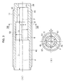
- a shock absorber 10 has an "outside tube", in other words, an outer tube 11.
- a male screw 12 is formed on an outer peripheral surface of the outer tube 11, and a nut 13 is screw-coupled to the male screw 12.
- the outer tube 11 is fastened to a member (not shown) with the nut 13.
- a piston rod 14 is mounted on the outer tube 11 and reciprocable in an axial direction.
- the piston rod 14 has a projecting end 14a projecting from a distal end of the outer tube 11.
- An inner tube 15 is rotatably mounted in the outer tube 11. In this manner, the shock absorber 10 has the dual-structured "inner/outer" tubes.
- a liquid accommodating chamber 16 is provided across the interior of the inner tube 15 and the space between the inner tube 15 and the outer tube 11.
- a closing part 18 is provided in a base end side of the inner tube 15, and a rotative operating part 19 having a cylindrical shape is provided at the closing part 18.
- the rotative operating part 19 extends through a through hole 20 provided at a base end of the outer tube 11, and projects outward in the axial direction.
- the piston rod 14 projects from one end of the outer tube 11, and this end serves as “distal end”.
- the other end in the opposite side of the outer tube 11 serves as “base end”.
- the projecting end 14a of the piston rod 14 serves as “distal end”
- the other end in the opposite side of the piston rod 14 serves as "base end” 14b.
- a liquid injecting hole 21 is provided in the closing part 18, and the liquid injecting hole 21 is opened to the base-end-side bottom surface of the liquid accommodating chamber 16.
- a stop screw 22 is screwed together, in other words, screw-fastened with the liquid injecting hole 21.
- the stop screw 22 is inserted from a mounting hole 23 provided in the rotative operating part 19.
- the liquid injecting hole 21 is closed by the stop screw 22.
- a seal member 24 is mounted at the stop screw 22.
- An annular adjusting knob 25 is attached to the rotative operating part 19.
- a hollow pin 26 is attached to the adjusting knob 25, and the hollow pin 26 extends through the rotative operating part 19.
- An operator rotates the adjusting knob 25 and adjusts the inner tube 15.
- a fixing screw member (not shown) is provided at the adjusting knob 25.
- An annular piston 27 is provided at the base end 14b of the piston rod 14.
- the annular piston 27 is disposed in the inner tube 15.
- the liquid accommodating chamber 16 is separated into a shock absorbing chamber 28 in the base end side of the inner tube 15 and an accumulator chamber 29 in the opposite side.
- a gap 30 is provided between the outer peripheral surface of the annular piston 27 and the inner peripheral surface of the inner tube 15.
- a flange 31 is provided at the base end of the piston rod 14, and a spring receiving member 32 is attached to the base end of the piston rod 14.
- the annular piston 27 is provided at the base end 14b disposed between a flange part 32a of the spring receiving member 32 and the flange 31, and the annular piston 27 is movable in the axial direction.
- a spring member in other words, a compression coil spring 33 is disposed in the liquid accommodating chamber 16.
- One end of the compression coil spring 33 abuts on the spring receiving member 32, and the other end of the compression coil spring 33 abuts on the closing part 18.
- a gap 34 is provided between the inner peripheral surface of the annular piston 27 and the outer peripheral surface of the piston rod 14.
- the gap 34 is larger than the gap 30.
- a plurality of grooves 35 opposed to the spring receiving member 32 are provided on the end face of the annular piston 27.
- a rod cover 36 is mounted at the distal end of the outer tube 11.
- a through hole 37 is provided in the rod cover 36, and the piston rod 14 is penetrating through the through hole 37 and projecting from the distal end of the outer tube 11 to the outer side.
- a seal member 38 is provided at an inner peripheral groove of the rod cover 36, and the seal member 38 seals the part between the piston rod 14 and the rod cover 36.
- a seal member 39 is provided at an outer peripheral groove of the rod cover 36, and the seal member 39 seals the part between the rod cover 36 and the outer tube 11.
- An end plate 41 is mounted at the distal end of the outer tube 11, the end plate 41 abuts on the rod cover 36, and the end plate 41 fixes the rod cover 36 to the outer tube 11.
- a housing groove 42 having a cylindrical shape is provided at an outer peripheral part of the rod cover 36, and the housing groove 42 is communicated to the accumulator chamber 29 in the side of an opening 17 of the inner tube 15.
- An accumulator member 43 having a cylindrical shape is mounted at the housing groove 42.
- the accumulator member 43 is formed of, for example, closed-pore sponge.
- the accumulator member 43 is provided at the rod cover 36 which guides the piston rod 14 in the axial direction. Since the accumulator member 43 is contracted and restored at such a position, the shock absorber 10 can be reduced in size without being increased in outer diameter of the shock absorber 10.
- a first fitting hole 45 is provided in the base end of the outer tube 11.
- the central axis of the first fitting hole 45 is coaxial with the rotation central axis "P" of the inner tube 15. Therefore, the base end of the inner tube 15 is rotatably supported by the fitting hole 45.
- a second fitting hole 46 is provided in the distal end of the outer tube 11, and the rod cover 36 is fixed to the second fitting hole 46.
- the central axis of the second fitting hole 46 is also coaxial with the rotation central axis "P".
- the entire inner peripheral surface of the first fitting hole 45 contacts the outer peripheral surface of the base end of the inner tube 15 and rotatably supports the inner tube 15. In this manner, by virtue of the machining operation of the fitting hole, the inner tube 15 can be smoothly rotated while maintaining the center of an axis.
- a seal member 47 is mounted at an annular groove provided on the outer peripheral surface of the closing part 18 of the inner tube 15, and the seal member 47 seals the part between the inner tube 15 and the fitting hole 45.
- a flow-rate adjusting hole 48 is positioned between both of the fitting holes 45 and 46 and is provided in the outer tube 11.
- the length of the first fitting hole 45 is L3
- the length of the flow-rate adjusting hole 48 is L2
- the length of the second fitting hole 46 is L1.
- communication holes 49 are provided so as to penetrate through the inner tube 15 in a radial direction.
- the communication holes 49 are provided at the positions close to the side of the first fitting hole 45 in the axial direction.
- the flow-rate adjusting hole 48 consists of a contact surface 51 and an eccentric surface 52, and the contact surface 51 contacts the outer peripheral surface of the inner tube 15.
- An eccentric central axis "Q" deviates from the rotation central axis "P" of the first fitting hole 45 and the second fitting hole 46 by an eccentric quantity "e”, and the eccentric surface 52 is a circular-arc surface having a center of the eccentric central axis "Q".
- a bypass channel 53 is formed between the eccentric surface 52 and the outer peripheral surface of the inner tube 15.
- the bypass channel 53 is communicated with the communication holes 49.
- the piston rod 14 When the piston rod 14 is moved in the axial direction, the liquid flows between the shock absorbing chamber 28 and the accumulator chamber 29 via the bypass channel 53.
- the bypass channel 53 reaches the maximum thickness at a circumferential-direction center part of the eccentric surface 52, and the bypass channel 53 is gradually reduced in thick with the decreasing distance from circumferential-direction both-side parts.
- the five communication holes 49 are provided so as to be mutually shifted in the circumferential direction.
- the five communication holes 49 are provided in the circumferential direction while using the rotation central axis "P" as the center thereof.
- the number of the communication holes 49 is not limited to five and may be one or any of plural numbers of two or more, but is preferred to be plural.
- the flow resistance of the liquid which flows through the communication holes 49 can be adjusted in a wide range.
- the radius of the contact surface 51 is slightly larger than the rotation radius Rp of the outer peripheral surface of the inner tube 15.
- the radius Rq of the eccentric surface 52 is set to be larger than the rotation radius Rp.
- the contact surface 51 is formed on the inner peripheral surface of the outer tube 11 and contacts the outer peripheral surface of the inner tube 15.
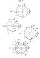
- FIG. 4A is a schematic view showing the relation between the rotation radius Rp of the inner tube 15 and the radius Rq of the eccentric surface 52 of the outer tube 11; wherein, the circle of the rotation radius Rp is shown by a broken line, and the circle of the radius Rq is shown by two-dot chain line.
- the eccentric quantity "e" is larger than the radius difference ⁇ R, the circle of the rotation radius Rp is shifted to the outer side than the circle of the radius Rq.
- Hole boring to the outer tube 11 is machined, for example, in the following procedure.
- hole boring of the through hole 20 is carried out across the entirety of the outer tube 11.
- the first fitting hole 45 is machined by the depth of L1+L2+L3 with the inner diameter of the rotation radius Rp.
- the second fitting hole 46 is machined by the depth of L1.
- the eccentric hole having the radius Rq is machined by the depth L2 about the eccentric central axis "Q", wherein the eccentric central axis "Q" is shifted by the eccentric quantity "e” from the previous boring center position.
- the eccentric surface 52 continued to the contact surface 51 is formed along the length L2.
- the bypass channel 53 is formed between the eccentric surface 52 of the outer tube 11 and the outer peripheral surface of the inner tube 15, and the bypass channel 53 is communicated with the communication holes 49.
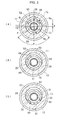
- FIG. 2A shows a state in which the five communication holes 49 are communicated with the bypass channel 53.
- the communication opening degree between the bypass channel 53 and the communication holes 49 is maximized, the bypass channel 53 and the shock absorbing chamber 28 are communicated with each other via all the communication holes 49, and the flow resistance of the liquid is minimized.
- FIG. 2A shows a state in which the communication hole 49 at the circumferential-direction center part is located at the circumferential-direction center part of the eccentric surface 52, wherein the thickness-direction dimension between the opening surfaces of all the communication holes 49 and the eccentric surface 52 becomes a maximum value.
- FIG. 2B shows a state in which the inner tube 15 is rotated by 90 degrees in a counterclockwise direction from the state of FIG. 2A .
- the two communication holes 49 are closed by the contact surface 51, and the three communication holes 49 are communicated with the bypass channel 53 in the shown state. Therefore, the communication opening degree between the bypass channel 53 and the communication hole 49 is smaller than that of the state shown in FIG. 2A .
- the thickness-direction dimension between opening surfaces of the communicated three communication holes 49 and the eccentric surface 52 is smaller than that of the case shown in FIG. 2A .
- FIG. 2C shows a state in which the inner tube 15 is rotated by 180 degrees from the state of FIG. 2A .
- this state all the communication holes 49 are closed by the contact surface 51, and the liquid does not flow through the communication holes 49 almost at all.
- the communication opening degree of the bypass channel 53 and each of the plurality of communication holes 49 is changed in a non-step manner from a completely-open position to a completely-closed position.
- the annular piston 27 is moved backward in the liquid accommodating chamber 16, the liquid in the shock absorbing chamber 28 flows toward the accumulator chamber 29 through the gap between the outer peripheral surface of the annular piston 27 and the inner peripheral surface of the inner tube 15, flows out to the bypass channel 53 via the communication holes 49, and flows to the accumulator chamber 29.
- the accumulator member 43 is contracted by the liquid flowed into the accumulator chamber 29.
- flow resistance is applied to the liquid which flows from the shock absorbing chamber 28 to the accumulator chamber 29; therefore, the kinetic energy of the moving member is damped.
- the impact force applied to the moving member is reduced.
- the moving member abuts on the end plate 41, the movement of the moving member is stopped. At the point when the moving member abuts on the end plate 41, the impact force applied to the moving member is reduced.
- the communication opening degree of the communication holes 49 can be changed in a non-step manner.
- the fixing screw member (not shown) provided at the adjusting knob 25 is loosened, and the inner tube 15 is then rotated.
- the adjusting knob 25 is provided so as to project from the base end of the outer tube 11. Therefore, a rotating operation of the inner tube 15 can be easily carried out in the base end side of the outer tube 11.
- the rotation angle of the inner tube 15 can be adjusted by operating the adjusting knob 25 in the base end side of the outer tube 11, in a state in which the shock absorber 10 is installed on a member, the communication opening degree of the communication holes 49 can be changed by the adjusting knob 25 while an operator collides the moving member with the piston rod 14 and checks the impact force of the moving member.
- the shock absorber 10 since the damping amount of the shock absorber 10 is adjusted by only two parts, i.e., the outer tube 11 and the inner tube 15, the shock absorber 10 can be reduced in the number of the constituent parts, and reduced in dimension in the axial and radial directions. Therefore, the shock absorber 10 can be reduced in size. Since the first fitting hole 45 for supporting the rotation of the inner tube 15 extends in the axial direction, the axis of the inner tube 15 is prevented from being deflected. Furthermore, the outer peripheral surface of the inner tube 15 is fitted in the fitting hole 45, and they can be easily improved in machining accuracy.
- the damping amount of the shock absorber 10 can be adjusted with accuracy from a completely-open position to a completely-closed position of the communication holes 49.
- the present invention is not limited to the above-described embodiment and can be variously modified within a range not departing from the gist thereof.
- the usage mode of the shock absorber 10 is not limited to the case in which the moving member is caused to collide with the piston rod 14 to cause the end plate 41 to abut on the moving member.
- the shock absorber 10 can be applied also to a case in which a vibrating member is attached to the distal end of the piston rod 14 to absorb the impact of the vibrating member.
Landscapes
- Engineering & Computer Science (AREA)
- General Engineering & Computer Science (AREA)
- Mechanical Engineering (AREA)
- Fluid-Damping Devices (AREA)
Applications Claiming Priority (1)
| Application Number | Priority Date | Filing Date | Title |
|---|---|---|---|
| JP2014124272A JP6259722B2 (ja) | 2014-06-17 | 2014-06-17 | ショックアブソーバ |
Publications (2)
| Publication Number | Publication Date |
|---|---|
| EP2957791A1 true EP2957791A1 (de) | 2015-12-23 |
| EP2957791B1 EP2957791B1 (de) | 2018-06-06 |
Family
ID=53397952
Family Applications (1)
| Application Number | Title | Priority Date | Filing Date |
|---|---|---|---|
| EP15172128.9A Active EP2957791B1 (de) | 2014-06-17 | 2015-06-15 | Stossdämpfer |
Country Status (5)
| Country | Link |
|---|---|
| US (1) | US9551395B2 (de) |
| EP (1) | EP2957791B1 (de) |
| JP (1) | JP6259722B2 (de) |
| CN (1) | CN204805421U (de) |
| TW (1) | TWI644030B (de) |
Families Citing this family (12)
| Publication number | Priority date | Publication date | Assignee | Title |
|---|---|---|---|---|
| JP6388567B2 (ja) * | 2015-07-24 | 2018-09-12 | 株式会社コガネイ | ショックアブソーバ |
| JP2017172777A (ja) * | 2016-03-25 | 2017-09-28 | 株式会社ショーワ | エアばね構造 |
| US11007834B2 (en) | 2016-12-15 | 2021-05-18 | Tenneco Automotive Operating Company Inc. | Baffle tube for damper with electromechanical valve |
| CN107044504B (zh) * | 2016-12-27 | 2019-01-11 | 徐州德高电动车科技有限公司 | 一种电动车减震器总成 |
| CN106704457B (zh) * | 2016-12-27 | 2018-12-07 | 浙江天力机车部件有限公司 | 一种汽车减震器总成 |
| US10987988B2 (en) * | 2017-06-28 | 2021-04-27 | Tenneco Automotive Operating Company Inc. | Damper with volume reducing insert |
| US10704641B2 (en) | 2017-12-15 | 2020-07-07 | Tenneco Automotive Operating Company Inc. | Baffle for damper with electromechanical valve |
| US10837515B2 (en) | 2019-02-11 | 2020-11-17 | Tenneco Automotive Operating Company Inc. | Damper baffle tube with elastomeric skirt |
| CN112610639B (zh) * | 2020-12-09 | 2022-07-19 | 西安精密机械研究所 | 一种弹簧式液压阻尼装置及阻尼方法 |
| US11959718B2 (en) * | 2021-04-16 | 2024-04-16 | Kyntec Corporation | Hydraulic recoil device for handgun applications |
| US11959529B1 (en) * | 2023-08-14 | 2024-04-16 | Alfred Franklin Nibecker | Allow air springs to be self-charging |
| CN117403622A (zh) * | 2023-11-30 | 2024-01-16 | 北京振冲工程机械有限公司 | 超深振冲施工用振冲器 |
Citations (6)
| Publication number | Priority date | Publication date | Assignee | Title |
|---|---|---|---|---|
| US4059175A (en) * | 1975-05-06 | 1977-11-22 | Dressell Jr Richard G | Linear force shock absorber |
| JPS59147132A (ja) * | 1983-02-09 | 1984-08-23 | Tsubakimoto Chain Co | 油圧緩衝器 |
| JPS6166235U (de) | 1984-10-08 | 1986-05-07 | ||
| JPH0628377U (ja) | 1992-09-18 | 1994-04-15 | 太陽鉄工株式会社 | 流体圧式緩衝装置 |
| EP1293702A2 (de) * | 2001-09-13 | 2003-03-19 | ArvinMeritor Technology, LLC | Stossdämpfereinheit |
| EP2017494A2 (de) * | 2007-07-16 | 2009-01-21 | Weforma Dämpfungstechnik GmbH | Stoßdämpfer und Verfahren zum Einstellen eines Stoßdämpfers |
Family Cites Families (13)
| Publication number | Priority date | Publication date | Assignee | Title |
|---|---|---|---|---|
| US2846029A (en) * | 1955-06-17 | 1958-08-05 | Cawley George | Hydraulic retarding device |
| US3201110A (en) * | 1963-11-07 | 1965-08-17 | Taccone Corp | Cushioning device |
| US3889934A (en) * | 1973-12-19 | 1975-06-17 | Houdaille Industries Inc | Hydraulic buffer |
| JPS5438270A (en) | 1977-08-31 | 1979-03-22 | Ishikawajima Harima Heavy Ind Co Ltd | Solidifying and forming method for ash collected from incinerator |
| JPS59141246U (ja) * | 1983-03-14 | 1984-09-20 | 不二精器株式会社 | 油圧式緩衝装置 |
| JPS6120938U (ja) * | 1984-07-12 | 1986-02-06 | 太陽鉄工株式会社 | シヨツクアブソ−バ |
| JPS6166235A (ja) | 1984-09-10 | 1986-04-05 | Toshiba Corp | 対物レンズ駆動装置 |
| US5050712A (en) * | 1989-04-25 | 1991-09-24 | Enertrols, Inc. | Shock absorber |
| JPH0628377A (ja) | 1992-07-10 | 1994-02-04 | Toshiba Corp | 帳票出力装置 |
| US5598904A (en) * | 1995-06-05 | 1997-02-04 | Enidine, Inc. | Adjustable energy absorption device |
| JP4195141B2 (ja) * | 1999-02-08 | 2008-12-10 | 不二ラテックス株式会社 | ショックアブソーバ |
| US6883650B2 (en) * | 2002-11-15 | 2005-04-26 | Arvinmeritor Technology, Llc. | Adjustable shock absorber |
| JP4517373B2 (ja) * | 2007-06-27 | 2010-08-04 | Smc株式会社 | ショックアブソーバ |
-
2014
- 2014-06-17 JP JP2014124272A patent/JP6259722B2/ja active Active
-
2015
- 2015-06-15 EP EP15172128.9A patent/EP2957791B1/de active Active
- 2015-06-15 US US14/739,527 patent/US9551395B2/en active Active
- 2015-06-17 CN CN201520419752.1U patent/CN204805421U/zh not_active Expired - Fee Related
- 2015-06-17 TW TW104119616A patent/TWI644030B/zh active
Patent Citations (6)
| Publication number | Priority date | Publication date | Assignee | Title |
|---|---|---|---|---|
| US4059175A (en) * | 1975-05-06 | 1977-11-22 | Dressell Jr Richard G | Linear force shock absorber |
| JPS59147132A (ja) * | 1983-02-09 | 1984-08-23 | Tsubakimoto Chain Co | 油圧緩衝器 |
| JPS6166235U (de) | 1984-10-08 | 1986-05-07 | ||
| JPH0628377U (ja) | 1992-09-18 | 1994-04-15 | 太陽鉄工株式会社 | 流体圧式緩衝装置 |
| EP1293702A2 (de) * | 2001-09-13 | 2003-03-19 | ArvinMeritor Technology, LLC | Stossdämpfereinheit |
| EP2017494A2 (de) * | 2007-07-16 | 2009-01-21 | Weforma Dämpfungstechnik GmbH | Stoßdämpfer und Verfahren zum Einstellen eines Stoßdämpfers |
Also Published As
| Publication number | Publication date |
|---|---|
| JP6259722B2 (ja) | 2018-01-10 |
| TWI644030B (zh) | 2018-12-11 |
| TW201600758A (zh) | 2016-01-01 |
| EP2957791B1 (de) | 2018-06-06 |
| US9551395B2 (en) | 2017-01-24 |
| US20150362040A1 (en) | 2015-12-17 |
| JP2016003710A (ja) | 2016-01-12 |
| CN204805421U (zh) | 2015-11-25 |
Similar Documents
| Publication | Publication Date | Title |
|---|---|---|
| EP2957791B1 (de) | Stossdämpfer | |
| CN107636344B (zh) | 用于车辆悬架的液压减震器 | |
| US8205729B2 (en) | Shock absorber | |
| EP3489540B1 (de) | Stossdämpfer mit hydraulischem kompressionsabsperrventil | |
| JP5561496B2 (ja) | 流量制御弁及びその組付方法 | |
| CN206617390U (zh) | 流体压力缸 | |
| EP3236105A1 (de) | Stossdämpfer | |
| US20040182662A1 (en) | Adjustable shock absorber | |
| CN108291603A (zh) | 阻尼器改进 | |
| CN110249154A (zh) | 压力缓冲装置 | |
| US20210164533A1 (en) | Vibration damper with adjustable damping force | |
| EP3456908A1 (de) | Schliessvorrichtung | |
| US10987988B2 (en) | Damper with volume reducing insert | |
| CN110050129B (zh) | 杆组装体及流体压力装置 | |
| US20200080612A1 (en) | Hydraulic damping device | |
| CN117006185A (zh) | 阻尼装置及包括该阻尼装置的阀 | |
| KR100502470B1 (ko) | 완충기 | |
| US10288142B2 (en) | Shock absorber | |
| WO2017051669A1 (ja) | 磁気粘性流体緩衝器 | |
| CN113242943B (zh) | 流体压力缓冲器 | |
| JP4885617B2 (ja) | ドアチェック装置 | |
| KR101664198B1 (ko) | 완충기 | |
| RU2437019C1 (ru) | Устройство для регулирования газообмена герметизированных объемов с внешней средой | |
| WO2017043253A1 (ja) | 磁気粘性流体緩衝器 | |
| EP4397892A1 (de) | Elektronisches expansionsventil |
Legal Events
| Date | Code | Title | Description |
|---|---|---|---|
| PUAI | Public reference made under article 153(3) epc to a published international application that has entered the european phase |
Free format text: ORIGINAL CODE: 0009012 |
|
| AK | Designated contracting states |
Kind code of ref document: A1 Designated state(s): AL AT BE BG CH CY CZ DE DK EE ES FI FR GB GR HR HU IE IS IT LI LT LU LV MC MK MT NL NO PL PT RO RS SE SI SK SM TR |
|
| AX | Request for extension of the european patent |
Extension state: BA ME |
|
| 17P | Request for examination filed |
Effective date: 20160614 |
|
| STAA | Information on the status of an ep patent application or granted ep patent |
Free format text: STATUS: EXAMINATION IS IN PROGRESS |
|
| 17Q | First examination report despatched |
Effective date: 20170320 |
|
| RIC1 | Information provided on ipc code assigned before grant |
Ipc: F16F 13/00 20060101ALI20171114BHEP Ipc: F16F 9/44 20060101AFI20171114BHEP |
|
| GRAP | Despatch of communication of intention to grant a patent |
Free format text: ORIGINAL CODE: EPIDOSNIGR1 |
|
| STAA | Information on the status of an ep patent application or granted ep patent |
Free format text: STATUS: GRANT OF PATENT IS INTENDED |
|
| INTG | Intention to grant announced |
Effective date: 20180117 |
|
| GRAS | Grant fee paid |
Free format text: ORIGINAL CODE: EPIDOSNIGR3 |
|
| GRAA | (expected) grant |
Free format text: ORIGINAL CODE: 0009210 |
|
| STAA | Information on the status of an ep patent application or granted ep patent |
Free format text: STATUS: THE PATENT HAS BEEN GRANTED |
|
| AK | Designated contracting states |
Kind code of ref document: B1 Designated state(s): AL AT BE BG CH CY CZ DE DK EE ES FI FR GB GR HR HU IE IS IT LI LT LU LV MC MK MT NL NO PL PT RO RS SE SI SK SM TR |
|
| REG | Reference to a national code |
Ref country code: GB Ref legal event code: FG4D |
|
| REG | Reference to a national code |
Ref country code: CH Ref legal event code: EP Ref country code: AT Ref legal event code: REF Ref document number: 1006436 Country of ref document: AT Kind code of ref document: T Effective date: 20180615 |
|
| REG | Reference to a national code |
Ref country code: IE Ref legal event code: FG4D |
|
| REG | Reference to a national code |
Ref country code: DE Ref legal event code: R096 Ref document number: 602015011627 Country of ref document: DE |
|
| REG | Reference to a national code |
Ref country code: NL Ref legal event code: MP Effective date: 20180606 |
|
| REG | Reference to a national code |
Ref country code: LT Ref legal event code: MG4D |
|
| PG25 | Lapsed in a contracting state [announced via postgrant information from national office to epo] |
Ref country code: NO Free format text: LAPSE BECAUSE OF FAILURE TO SUBMIT A TRANSLATION OF THE DESCRIPTION OR TO PAY THE FEE WITHIN THE PRESCRIBED TIME-LIMIT Effective date: 20180906 Ref country code: BG Free format text: LAPSE BECAUSE OF FAILURE TO SUBMIT A TRANSLATION OF THE DESCRIPTION OR TO PAY THE FEE WITHIN THE PRESCRIBED TIME-LIMIT Effective date: 20180906 Ref country code: LT Free format text: LAPSE BECAUSE OF FAILURE TO SUBMIT A TRANSLATION OF THE DESCRIPTION OR TO PAY THE FEE WITHIN THE PRESCRIBED TIME-LIMIT Effective date: 20180606 Ref country code: FI Free format text: LAPSE BECAUSE OF FAILURE TO SUBMIT A TRANSLATION OF THE DESCRIPTION OR TO PAY THE FEE WITHIN THE PRESCRIBED TIME-LIMIT Effective date: 20180606 Ref country code: CY Free format text: LAPSE BECAUSE OF FAILURE TO SUBMIT A TRANSLATION OF THE DESCRIPTION OR TO PAY THE FEE WITHIN THE PRESCRIBED TIME-LIMIT Effective date: 20180606 Ref country code: ES Free format text: LAPSE BECAUSE OF FAILURE TO SUBMIT A TRANSLATION OF THE DESCRIPTION OR TO PAY THE FEE WITHIN THE PRESCRIBED TIME-LIMIT Effective date: 20180606 Ref country code: SE Free format text: LAPSE BECAUSE OF FAILURE TO SUBMIT A TRANSLATION OF THE DESCRIPTION OR TO PAY THE FEE WITHIN THE PRESCRIBED TIME-LIMIT Effective date: 20180606 |
|
| PG25 | Lapsed in a contracting state [announced via postgrant information from national office to epo] |
Ref country code: RS Free format text: LAPSE BECAUSE OF FAILURE TO SUBMIT A TRANSLATION OF THE DESCRIPTION OR TO PAY THE FEE WITHIN THE PRESCRIBED TIME-LIMIT Effective date: 20180606 Ref country code: HR Free format text: LAPSE BECAUSE OF FAILURE TO SUBMIT A TRANSLATION OF THE DESCRIPTION OR TO PAY THE FEE WITHIN THE PRESCRIBED TIME-LIMIT Effective date: 20180606 Ref country code: LV Free format text: LAPSE BECAUSE OF FAILURE TO SUBMIT A TRANSLATION OF THE DESCRIPTION OR TO PAY THE FEE WITHIN THE PRESCRIBED TIME-LIMIT Effective date: 20180606 Ref country code: GR Free format text: LAPSE BECAUSE OF FAILURE TO SUBMIT A TRANSLATION OF THE DESCRIPTION OR TO PAY THE FEE WITHIN THE PRESCRIBED TIME-LIMIT Effective date: 20180907 |
|
| REG | Reference to a national code |
Ref country code: AT Ref legal event code: MK05 Ref document number: 1006436 Country of ref document: AT Kind code of ref document: T Effective date: 20180606 |
|
| PG25 | Lapsed in a contracting state [announced via postgrant information from national office to epo] |
Ref country code: NL Free format text: LAPSE BECAUSE OF FAILURE TO SUBMIT A TRANSLATION OF THE DESCRIPTION OR TO PAY THE FEE WITHIN THE PRESCRIBED TIME-LIMIT Effective date: 20180606 |
|
| PG25 | Lapsed in a contracting state [announced via postgrant information from national office to epo] |
Ref country code: IS Free format text: LAPSE BECAUSE OF FAILURE TO SUBMIT A TRANSLATION OF THE DESCRIPTION OR TO PAY THE FEE WITHIN THE PRESCRIBED TIME-LIMIT Effective date: 20181006 Ref country code: PL Free format text: LAPSE BECAUSE OF FAILURE TO SUBMIT A TRANSLATION OF THE DESCRIPTION OR TO PAY THE FEE WITHIN THE PRESCRIBED TIME-LIMIT Effective date: 20180606 Ref country code: AT Free format text: LAPSE BECAUSE OF FAILURE TO SUBMIT A TRANSLATION OF THE DESCRIPTION OR TO PAY THE FEE WITHIN THE PRESCRIBED TIME-LIMIT Effective date: 20180606 Ref country code: EE Free format text: LAPSE BECAUSE OF FAILURE TO SUBMIT A TRANSLATION OF THE DESCRIPTION OR TO PAY THE FEE WITHIN THE PRESCRIBED TIME-LIMIT Effective date: 20180606 Ref country code: CZ Free format text: LAPSE BECAUSE OF FAILURE TO SUBMIT A TRANSLATION OF THE DESCRIPTION OR TO PAY THE FEE WITHIN THE PRESCRIBED TIME-LIMIT Effective date: 20180606 Ref country code: RO Free format text: LAPSE BECAUSE OF FAILURE TO SUBMIT A TRANSLATION OF THE DESCRIPTION OR TO PAY THE FEE WITHIN THE PRESCRIBED TIME-LIMIT Effective date: 20180606 Ref country code: SK Free format text: LAPSE BECAUSE OF FAILURE TO SUBMIT A TRANSLATION OF THE DESCRIPTION OR TO PAY THE FEE WITHIN THE PRESCRIBED TIME-LIMIT Effective date: 20180606 |
|
| REG | Reference to a national code |
Ref country code: CH Ref legal event code: PL |
|
| PG25 | Lapsed in a contracting state [announced via postgrant information from national office to epo] |
Ref country code: SM Free format text: LAPSE BECAUSE OF FAILURE TO SUBMIT A TRANSLATION OF THE DESCRIPTION OR TO PAY THE FEE WITHIN THE PRESCRIBED TIME-LIMIT Effective date: 20180606 Ref country code: IT Free format text: LAPSE BECAUSE OF FAILURE TO SUBMIT A TRANSLATION OF THE DESCRIPTION OR TO PAY THE FEE WITHIN THE PRESCRIBED TIME-LIMIT Effective date: 20180606 |
|
| REG | Reference to a national code |
Ref country code: BE Ref legal event code: MM Effective date: 20180630 |
|
| REG | Reference to a national code |
Ref country code: DE Ref legal event code: R097 Ref document number: 602015011627 Country of ref document: DE |
|
| REG | Reference to a national code |
Ref country code: IE Ref legal event code: MM4A |
|
| PG25 | Lapsed in a contracting state [announced via postgrant information from national office to epo] |
Ref country code: MC Free format text: LAPSE BECAUSE OF FAILURE TO SUBMIT A TRANSLATION OF THE DESCRIPTION OR TO PAY THE FEE WITHIN THE PRESCRIBED TIME-LIMIT Effective date: 20180606 Ref country code: LU Free format text: LAPSE BECAUSE OF NON-PAYMENT OF DUE FEES Effective date: 20180615 |
|
| PLBE | No opposition filed within time limit |
Free format text: ORIGINAL CODE: 0009261 |
|
| STAA | Information on the status of an ep patent application or granted ep patent |
Free format text: STATUS: NO OPPOSITION FILED WITHIN TIME LIMIT |
|
| PG25 | Lapsed in a contracting state [announced via postgrant information from national office to epo] |
Ref country code: IE Free format text: LAPSE BECAUSE OF NON-PAYMENT OF DUE FEES Effective date: 20180615 Ref country code: LI Free format text: LAPSE BECAUSE OF NON-PAYMENT OF DUE FEES Effective date: 20180630 Ref country code: CH Free format text: LAPSE BECAUSE OF NON-PAYMENT OF DUE FEES Effective date: 20180630 |
|
| 26N | No opposition filed |
Effective date: 20190307 |
|
| PG25 | Lapsed in a contracting state [announced via postgrant information from national office to epo] |
Ref country code: BE Free format text: LAPSE BECAUSE OF NON-PAYMENT OF DUE FEES Effective date: 20180630 Ref country code: SI Free format text: LAPSE BECAUSE OF FAILURE TO SUBMIT A TRANSLATION OF THE DESCRIPTION OR TO PAY THE FEE WITHIN THE PRESCRIBED TIME-LIMIT Effective date: 20180606 Ref country code: DK Free format text: LAPSE BECAUSE OF FAILURE TO SUBMIT A TRANSLATION OF THE DESCRIPTION OR TO PAY THE FEE WITHIN THE PRESCRIBED TIME-LIMIT Effective date: 20180606 |
|
| PG25 | Lapsed in a contracting state [announced via postgrant information from national office to epo] |
Ref country code: FR Free format text: LAPSE BECAUSE OF NON-PAYMENT OF DUE FEES Effective date: 20180806 |
|
| PG25 | Lapsed in a contracting state [announced via postgrant information from national office to epo] |
Ref country code: AL Free format text: LAPSE BECAUSE OF FAILURE TO SUBMIT A TRANSLATION OF THE DESCRIPTION OR TO PAY THE FEE WITHIN THE PRESCRIBED TIME-LIMIT Effective date: 20180606 |
|
| PG25 | Lapsed in a contracting state [announced via postgrant information from national office to epo] |
Ref country code: MT Free format text: LAPSE BECAUSE OF NON-PAYMENT OF DUE FEES Effective date: 20180615 |
|
| GBPC | Gb: european patent ceased through non-payment of renewal fee |
Effective date: 20190615 |
|
| PG25 | Lapsed in a contracting state [announced via postgrant information from national office to epo] |
Ref country code: TR Free format text: LAPSE BECAUSE OF FAILURE TO SUBMIT A TRANSLATION OF THE DESCRIPTION OR TO PAY THE FEE WITHIN THE PRESCRIBED TIME-LIMIT Effective date: 20180606 |
|
| PG25 | Lapsed in a contracting state [announced via postgrant information from national office to epo] |
Ref country code: GB Free format text: LAPSE BECAUSE OF NON-PAYMENT OF DUE FEES Effective date: 20190615 |
|
| PG25 | Lapsed in a contracting state [announced via postgrant information from national office to epo] |
Ref country code: PT Free format text: LAPSE BECAUSE OF FAILURE TO SUBMIT A TRANSLATION OF THE DESCRIPTION OR TO PAY THE FEE WITHIN THE PRESCRIBED TIME-LIMIT Effective date: 20180606 |
|
| PG25 | Lapsed in a contracting state [announced via postgrant information from national office to epo] |
Ref country code: MK Free format text: LAPSE BECAUSE OF NON-PAYMENT OF DUE FEES Effective date: 20180606 Ref country code: HU Free format text: LAPSE BECAUSE OF FAILURE TO SUBMIT A TRANSLATION OF THE DESCRIPTION OR TO PAY THE FEE WITHIN THE PRESCRIBED TIME-LIMIT; INVALID AB INITIO Effective date: 20150615 |
|
| PGFP | Annual fee paid to national office [announced via postgrant information from national office to epo] |
Ref country code: DE Payment date: 20250429 Year of fee payment: 11 |