EP2957812A2 - Verfahren zur herstellung eines abzweigs eines vorisolierten rohrs - Google Patents
Verfahren zur herstellung eines abzweigs eines vorisolierten rohrs Download PDFInfo
- Publication number
- EP2957812A2 EP2957812A2 EP15388002.6A EP15388002A EP2957812A2 EP 2957812 A2 EP2957812 A2 EP 2957812A2 EP 15388002 A EP15388002 A EP 15388002A EP 2957812 A2 EP2957812 A2 EP 2957812A2
- Authority
- EP
- European Patent Office
- Prior art keywords
- pipe
- medium conveying
- insulated
- hole
- branch pipe
- Prior art date
- Legal status (The legal status is an assumption and is not a legal conclusion. Google has not performed a legal analysis and makes no representation as to the accuracy of the status listed.)
- Withdrawn
Links
Images


Classifications
-
- F—MECHANICAL ENGINEERING; LIGHTING; HEATING; WEAPONS; BLASTING
- F16—ENGINEERING ELEMENTS AND UNITS; GENERAL MEASURES FOR PRODUCING AND MAINTAINING EFFECTIVE FUNCTIONING OF MACHINES OR INSTALLATIONS; THERMAL INSULATION IN GENERAL
- F16L—PIPES; JOINTS OR FITTINGS FOR PIPES; SUPPORTS FOR PIPES, CABLES OR PROTECTIVE TUBING; MEANS FOR THERMAL INSULATION IN GENERAL
- F16L59/00—Thermal insulation in general
- F16L59/14—Arrangements for the insulation of pipes or pipe systems
- F16L59/16—Arrangements specially adapted to local requirements at flanges, junctions, valves or the like
- F16L59/163—Branch units; Insulation forming a whole with branches
-
- B—PERFORMING OPERATIONS; TRANSPORTING
- B23—MACHINE TOOLS; METAL-WORKING NOT OTHERWISE PROVIDED FOR
- B23K—SOLDERING OR UNSOLDERING; WELDING; CLADDING OR PLATING BY SOLDERING OR WELDING; CUTTING BY APPLYING HEAT LOCALLY, e.g. FLAME CUTTING; WORKING BY LASER BEAM
- B23K9/00—Arc welding or cutting
- B23K9/0026—Arc welding or cutting specially adapted for particular articles or work
-
- B—PERFORMING OPERATIONS; TRANSPORTING
- B23—MACHINE TOOLS; METAL-WORKING NOT OTHERWISE PROVIDED FOR
- B23K—SOLDERING OR UNSOLDERING; WELDING; CLADDING OR PLATING BY SOLDERING OR WELDING; CUTTING BY APPLYING HEAT LOCALLY, e.g. FLAME CUTTING; WORKING BY LASER BEAM
- B23K9/00—Arc welding or cutting
- B23K9/02—Seam welding; Backing means; Inserts
- B23K9/032—Seam welding; Backing means; Inserts for three-dimensional [3D] seams
-
- B—PERFORMING OPERATIONS; TRANSPORTING
- B23—MACHINE TOOLS; METAL-WORKING NOT OTHERWISE PROVIDED FOR
- B23K—SOLDERING OR UNSOLDERING; WELDING; CLADDING OR PLATING BY SOLDERING OR WELDING; CUTTING BY APPLYING HEAT LOCALLY, e.g. FLAME CUTTING; WORKING BY LASER BEAM
- B23K9/00—Arc welding or cutting
- B23K9/16—Arc welding or cutting making use of shielding gas
- B23K9/167—Arc welding or cutting making use of shielding gas and of a non-consumable electrode
-
- F—MECHANICAL ENGINEERING; LIGHTING; HEATING; WEAPONS; BLASTING
- F16—ENGINEERING ELEMENTS AND UNITS; GENERAL MEASURES FOR PRODUCING AND MAINTAINING EFFECTIVE FUNCTIONING OF MACHINES OR INSTALLATIONS; THERMAL INSULATION IN GENERAL
- F16L—PIPES; JOINTS OR FITTINGS FOR PIPES; SUPPORTS FOR PIPES, CABLES OR PROTECTIVE TUBING; MEANS FOR THERMAL INSULATION IN GENERAL
- F16L13/00—Non-disconnectable pipe joints, e.g. soldered, adhesive, or caulked joints
- F16L13/02—Welded joints
- F16L13/0254—Welded joints the pipes having an internal or external coating
- F16L13/0272—Welded joints the pipes having an internal or external coating having an external coating
-
- F—MECHANICAL ENGINEERING; LIGHTING; HEATING; WEAPONS; BLASTING
- F16—ENGINEERING ELEMENTS AND UNITS; GENERAL MEASURES FOR PRODUCING AND MAINTAINING EFFECTIVE FUNCTIONING OF MACHINES OR INSTALLATIONS; THERMAL INSULATION IN GENERAL
- F16L—PIPES; JOINTS OR FITTINGS FOR PIPES; SUPPORTS FOR PIPES, CABLES OR PROTECTIVE TUBING; MEANS FOR THERMAL INSULATION IN GENERAL
- F16L41/00—Branching pipes; Joining pipes to walls
- F16L41/08—Joining pipes to walls or pipes, the joined pipe axis being perpendicular to the plane of a wall or to the axis of another pipe
- F16L41/082—Non-disconnectable joints, e.g. soldered, adhesive or caulked joints
- F16L41/084—Soldered joints
-
- B—PERFORMING OPERATIONS; TRANSPORTING
- B23—MACHINE TOOLS; METAL-WORKING NOT OTHERWISE PROVIDED FOR
- B23K—SOLDERING OR UNSOLDERING; WELDING; CLADDING OR PLATING BY SOLDERING OR WELDING; CUTTING BY APPLYING HEAT LOCALLY, e.g. FLAME CUTTING; WORKING BY LASER BEAM
- B23K2101/00—Articles made by soldering, welding or cutting
- B23K2101/04—Tubular or hollow articles
- B23K2101/06—Tubes
-
- F—MECHANICAL ENGINEERING; LIGHTING; HEATING; WEAPONS; BLASTING
- F16—ENGINEERING ELEMENTS AND UNITS; GENERAL MEASURES FOR PRODUCING AND MAINTAINING EFFECTIVE FUNCTIONING OF MACHINES OR INSTALLATIONS; THERMAL INSULATION IN GENERAL
- F16L—PIPES; JOINTS OR FITTINGS FOR PIPES; SUPPORTS FOR PIPES, CABLES OR PROTECTIVE TUBING; MEANS FOR THERMAL INSULATION IN GENERAL
- F16L59/00—Thermal insulation in general
- F16L59/14—Arrangements for the insulation of pipes or pipe systems
- F16L59/143—Pre-insulated pipes
-
- F—MECHANICAL ENGINEERING; LIGHTING; HEATING; WEAPONS; BLASTING
- F16—ENGINEERING ELEMENTS AND UNITS; GENERAL MEASURES FOR PRODUCING AND MAINTAINING EFFECTIVE FUNCTIONING OF MACHINES OR INSTALLATIONS; THERMAL INSULATION IN GENERAL
- F16L—PIPES; JOINTS OR FITTINGS FOR PIPES; SUPPORTS FOR PIPES, CABLES OR PROTECTIVE TUBING; MEANS FOR THERMAL INSULATION IN GENERAL
- F16L59/00—Thermal insulation in general
- F16L59/14—Arrangements for the insulation of pipes or pipe systems
- F16L59/16—Arrangements specially adapted to local requirements at flanges, junctions, valves or the like
- F16L59/18—Arrangements specially adapted to local requirements at flanges, junctions, valves or the like adapted for joints
- F16L59/20—Arrangements specially adapted to local requirements at flanges, junctions, valves or the like adapted for joints for non-disconnectable joints
Definitions
- the present invention relates to insulated medium conveying pipes. More specifically, the present invention relates to a process for producing a branch on a pre-insulated pipe, and to insulated branched medium conveying pipes obtainable by the process.
- One aspect relates to a process for producing a T-branch on a pre-insulated pipe comprising:
- Another aspect relates to a process for producing an insulated branched medium conveying pipe comprising:
- Yet another aspect relates to an insulated branched medium conveying pipe obtainable by the process according to the present invention.
- pre-insulated pipes For district heating and cooling solutions in e.g. the oil and gas sector and for solar heating systems, pre-insulated pipes are widely used.
- An assembly of a pre-insulated pipe typically comprises one or more inner pipes (medium conveying pipes) of either metal or plastic, an insulation layer such as polyurethane foam, and a casing pipe (jacket pipe) of metal or plastic.
- Pre-insulated pipes that are continuously manufactured can further comprise a diffusion barrier in the form of e.g. a film or foil arranged between the insulation layer and the casing material.
- Still another aspect relates to the use of a metal collar in the production of insulated branched medium conveying pipes for protecting exposed insulation material during welding.
- the process comprises providing a pre-insulated pipe comprising a medium conveying pipe of metal, an insulating material surrounding at least a part of the length of the medium conveying pipe and a first jacket pipe at least partly surrounding the insulating material.
- a hole is made in the pre-insulated pipe by removing a part of the jacket pipe and the underlying insulating material so as to expose a part of the medium conveying pipe. Thereafter, a hole is made in the exposed part of the medium conveying pipe.
- a branch pipe of metal is provided for attachment to the medium conveying pipe.
- One end (the first end) of the branch pipe is positioned within the hole of the exposed part of the medium conveying pipe, when the diameter of the branch pipe is smaller than the diameter of the hole.
- the diameter of the hole in the exposed part of the medium conveying pipe is at most 2 mm larger than the outer diameter of the branch pipe, such as within the range of 0.001-2 mm larger, e.g. at most 1.5 mm larger, such as within the range of 0.01-1.5 mm larger, e.g. at most 1.0 mm larger, such as within the range of 0.1-1.0 mm larger, e.g. at most 0.5 mm larger, such as within the range of 0.2-0.5 mm larger than the outer diameter of the branch pipe. This is important to obtain a proper fillet welding between the medium conveying pipe and the branch pipe.
- one end (the first end) of the branch pipe is positioned around the opening of the hole of the exposed part of the medium conveying pipe, when the diameter of the branch pipe is larger than the diameter of the hole.
- the process further comprises the step of arch welding the first end of the branch pipe to the exposed part of the medium conveying pipe using an inert (e.g. argon or helium) or semi-inert (such as carbon dioxide) shielding gas, thereby forming a first fillet weld along the entire circumference of the branch pipe.
- an inert e.g. argon or helium
- semi-inert such as carbon dioxide
- Tungsten Inert Gas (TIG) welding is an arc welding process that uses a non-consumable tungsten electrode to produce the weld.
- the weld area is protected from atmospheric contamination by an inert shielding gas, and a filler metal is normally used.
- a constant-current welding power supply produces energy which is conducted across the arc through a column of highly ionized gas and metal vapours known as a plasma.
- the arch welding is tungsten inert gas welding.
- the process further comprises the step of attaching a compensating plate (reinforcement plate) to the exposed part of the medium conveying pipe and along the entire circumference of the branch pipe.
- a compensating plate reinforcement plate
- the process further comprises the step of insulating the branch pipe with an insulating material.
- the process further comprises the step of insulating the branch pipe with an insulating material; and wherein the insulation step comprises:
- the process further comprises the step of insulating the branch pipe with an insulating material; and wherein the insulation step comprises:
- Insulating material in fluid form may be any type known to the skilled person.
- a well-known insulating material in fluid form is based on polyol and isocyanate (a polyurethane foaming mixture).
- the insulating material in fluid form is a polyurethane foaming mixture.
- the insulating material in fluid form may in one or more embodiments be applied by any discontinuous pipe filling technique known within the art.
- Discontinuous pipe filling techniques include the pour rise technique, the top filling technique, the horizontal mid-point filling technique, the pour-pull technique and the lance withdrawal technique.
- the pour rise technique and the top filling technique are preferred.
- the pipe to be filled is placed in an angle to the horizontal position, and the foaming mixture is injected into the cavity between the inner pipe and the outer casing at the bottom respectively at the top of the pipe, after which the foaming reaction occurs inside the cavity.
- Discontinuous pipe filling techniques require a foam formulation with very good flow properties, so that the entire cavity is filled with foam while at the same time achieving an even distribution of foam properties.
- a preformed tubular insulation adapted for application around the branch pipe.
- the inner diameter of a preformed tubular insulation is thereby dependant on the outer diameter of the branch pipe.
- at least a part of the insulating material is a preformed tubular insulation.
- a foaming mixture is injected into the hole in the pre-insulated pipe, and the preformed tubular insulation is mounted subsequently.
- the process further comprises the step of insulating the branch pipe with an insulating material; and wherein the insulation step comprises:
- the diameter of the hole in the pre-insulated pipe is at most 2 mm larger than the outer diameter of the second jacket pipe (the jacket pipe of the insulated branch pipe), such as within the range of 0.001-2 mm larger, e.g. at most 1.5 mm larger, such as within the range of 0.01-1.5 mm larger, e.g. at most 1.0 mm larger, such as within the range of 0.1-1.0 mm larger, e.g. at most 0.5 mm larger, such as within the range of 0.2-0.5 mm larger than the outer diameter of the second jacket pipe.
- This is important to obtain a proper welding between the first jacket pipe (the jacket pipe of the pre-insulated pipe) and the second jacket pipes.
- the diameter ratio between the branch pipe and the medium conveying pipe is at most 0.8. This is in order to fulfil the requirements of European Standard (EN) EN 13941:2009+A1:2010.
- a metal collar for protecting the exposed insulation material in the hole of the pre-insulated pipe may be inserted between the exposed insulation material and the branch pipe.
- the process before arch welding the first end of the branch pipe to the exposed part of the medium conveying pipe, the process further comprises the step of protecting the exposed insulation material in the hole of the pre-insulated pipe by positioning a metal collar between the exposed insulation material and the branch pipe.
- the pre-insulated pipe further comprises a diffusion barrier in the form of e.g. a film or foil arranged between the insulation material and the first jacket pipe.
- a diffusion barrier in the form of e.g. a film or foil arranged between the insulation material and the first jacket pipe.
- the average lambda value is the recognised parameter used when calculating heat loss for pre-insulated pipes.
- the lambda value depends on the temperature. This makes it necessary to carry out measurements at a minimum of three different temperatures. The measurements are carried out on a section of a DN 50/125-140 pre-insulated pipe at least 3 metres long. This section is taken from a 12-metre length of pipe from the normal production line.
- the temperature of the surroundings (ta) is kept constant while the measurements are being carried out.
- the temperature on the casing pipe is measured, when the temperature of the service pipe is constant.
- the lambda value for the three different temperature conditions can then be calculated on the basis of the temperatures of the service pipe, the casing pipe and of the surroundings.
- the lambda value for a pre-insulated district heating pipe is always given by an average temperature in the polyurethane foam at a temperature of 50°C.
- a straight line can be plotted for the calculated lambda values, because the lambda value is directly proportional to the temperature.
- the pre-insulated pipe has an average lambda value of at most 0.025 W/mK, such as within the range of 0.020-0.025 W/mK, e.g. at most 0.024 W/mK, such as within the range of 0.021-0.024 W/mK, e.g. at most 0.022 W/mK.
- the jacket pipe of the pre-insulated pipe and the branch pipe are preferably of the same material in order to connect them properly; and may be of plastic or metal.
- a pre-insulated pipe 100 comprises a medium conveying pipe 102 of metal, an insulating material 104 surrounding the medium conveying pipe 102 (except from the ends), and a jacket pipe 106 surrounding the insulating material 104.
- a hole 108 is made in the pre-insulated pipe 100 by removing a part of the jacket pipe 106 and the underlying insulating material so as to expose a part 110 of the medium conveying pipe 102.
- the hole 108 is made of a size such that a branch pipe 200 and a compensating plate 300 can be welded onto the exposed part 110 of the medium conveying pipe 102.
- a hole 112 is then made in the exposed part 110 of the medium conveying pipe 102, such that the branch pipe 200 can be in liquid communication with the medium conveying pipe 102.
- the first end 202 of the branch pipe 200 is positioned within the hole 112 of the exposed part 110 of the medium conveying pipe 102; and is then attached thereto by Tungsten Inert Gas (TIG) welding, thereby forming a first fillet weld along the entire circumference of the branch pipe 200.
- Tungsten Inert Gas (TIG) welding Tungsten Inert Gas
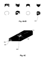
- a metal collar 600 for protecting the exposed insulation material in the hole 108 of the pre-insulated pipe is inserted between the exposed insulation material and the branch pipe.
- Figures 4A-B show different views of the metal collar, and its position between the exposed insulation material and the branch pipe is shown in Figure 4C .
- a jacket pipe 400 is positioned around the length of the branch pipe (except the upper end portion) and is then attached to the jacket pipe 106 of the pre-insulated pipe 100 by welding.
- a polyurethane foaming mixture (Component nr. 0700; poseskum 2) is then introduced into the hole 108 of the pre-insulated pipe 100; followed by the mounting of a preformed tubular insulation into said hole and around the branch pipe 200.
Landscapes
- Engineering & Computer Science (AREA)
- General Engineering & Computer Science (AREA)
- Mechanical Engineering (AREA)
- Physics & Mathematics (AREA)
- Plasma & Fusion (AREA)
- Thermal Insulation (AREA)
- Manufacturing Of Electrical Connectors (AREA)
Applications Claiming Priority (1)
| Application Number | Priority Date | Filing Date | Title |
|---|---|---|---|
| DK201470357A DK178155B1 (en) | 2014-06-16 | 2014-06-16 | A process for producing a branch on a pre-insulated pipe |
Publications (2)
| Publication Number | Publication Date |
|---|---|
| EP2957812A2 true EP2957812A2 (de) | 2015-12-23 |
| EP2957812A3 EP2957812A3 (de) | 2016-04-06 |
Family
ID=53298309
Family Applications (1)
| Application Number | Title | Priority Date | Filing Date |
|---|---|---|---|
| EP15388002.6A Withdrawn EP2957812A3 (de) | 2014-06-16 | 2015-04-15 | Verfahren zur herstellung eines abzweigs eines vorisolierten rohrs |
Country Status (2)
| Country | Link |
|---|---|
| EP (1) | EP2957812A3 (de) |
| DK (1) | DK178155B1 (de) |
Cited By (2)
| Publication number | Priority date | Publication date | Assignee | Title |
|---|---|---|---|---|
| US10352494B2 (en) | 2014-03-28 | 2019-07-16 | Public Joint Stock Company “Transneft” | Method for thermally insulating welded joints of pre-insulated pipes |
| EP4012240A1 (de) | 2020-12-09 | 2022-06-15 | Georg Fischer Rohrleitungssysteme AG | Abzweigrohr für sensoranschluss |
Family Cites Families (14)
| Publication number | Priority date | Publication date | Assignee | Title |
|---|---|---|---|---|
| FR1152651A (fr) * | 1956-03-30 | 1958-02-21 | Caliqua | Perfectionnement aux réseaux de transport d'énergie thermique sous forme de fluidefroid ou chaud |
| FR1431797A (fr) * | 1965-02-02 | 1966-03-18 | Tubes De La Providence | Dispositif de raccordement étanche pour des tubes métalliques présentant un revêtement intérieur |
| GB1311472A (en) * | 1969-03-18 | 1973-03-28 | Rasmussen As E | Pipe system of heat insulated pipes including means for detecting the presence of moisture |
| US3965555A (en) * | 1973-06-06 | 1976-06-29 | English Clays Lovering Pochin & Company Limited | Method of forming joints for protectively lined or coated metal |
| US4484386A (en) * | 1982-11-01 | 1984-11-27 | Rovanco Corp. | Method of field insulating pipe joints |
| GB8306693D0 (en) * | 1983-03-11 | 1983-04-20 | Raychem Sa Nv | Reinsulation of pipe joints |
| DE3400045A1 (de) * | 1984-01-03 | 1985-07-18 | kabelmetal electro GmbH, 3000 Hannover | Verfahren zur herstellung eines abzweiges an einer waermeisolierten rohrleitung |
| DE3814779C2 (de) * | 1988-04-21 | 1994-10-13 | Kabelmetal Electro Gmbh | Anordnung zum Umhüllen eines mit einem abzweigenden Teil versehenen Substrates |
| EP0636829A1 (de) * | 1993-07-26 | 1995-02-01 | N.V. Pgem | Rohrverbindung mit einer Isolationsumkleidung und einer Abdeckung für diese |
| GB2322423B (en) * | 1997-02-17 | 1998-12-30 | T J Corbishley | Improvements in connecting tubular members |
| NL1029434C2 (nl) * | 2005-07-05 | 2007-01-08 | Thermaflex Internat Holding B | Behuizing voor geïsoleerde leidingen. |
| DE202007004606U1 (de) * | 2007-03-29 | 2007-06-06 | Brugg Rohr Ag, Holding | Vorrichtung zur Herstellung eines Abzweigs an einer verlegten Rohrleitung |
| CA2647972A1 (en) * | 2008-12-19 | 2010-06-19 | Shawcor Ltd. | Method of filling a casing |
| DE102010022354A1 (de) * | 2009-12-23 | 2011-06-30 | isoplus Fernwärmetechnik GmbH, 99706 | Kunststoffmantelrohr und Verfahren zu dessen Herstellung |
-
2014
- 2014-06-16 DK DK201470357A patent/DK178155B1/en not_active IP Right Cessation
-
2015
- 2015-04-15 EP EP15388002.6A patent/EP2957812A3/de not_active Withdrawn
Cited By (2)
| Publication number | Priority date | Publication date | Assignee | Title |
|---|---|---|---|---|
| US10352494B2 (en) | 2014-03-28 | 2019-07-16 | Public Joint Stock Company “Transneft” | Method for thermally insulating welded joints of pre-insulated pipes |
| EP4012240A1 (de) | 2020-12-09 | 2022-06-15 | Georg Fischer Rohrleitungssysteme AG | Abzweigrohr für sensoranschluss |
Also Published As
| Publication number | Publication date |
|---|---|
| EP2957812A3 (de) | 2016-04-06 |
| DK178155B1 (en) | 2015-07-06 |
Similar Documents
| Publication | Publication Date | Title |
|---|---|---|
| US11204127B2 (en) | Vacuum insulated structure with end fitting and method of making same | |
| JP6113236B2 (ja) | 電気フィードスルーおよびその使用 | |
| JP4753696B2 (ja) | 水素充填装置 | |
| EP3033192B1 (de) | Objektherstellung | |
| US7494155B2 (en) | Pipeline for the transportation of liquefied natural gas | |
| KR20130118869A (ko) | 하이브리드 복합 절연재를 포함한 히트 트레이스 시스템 | |
| EP2957812A2 (de) | Verfahren zur herstellung eines abzweigs eines vorisolierten rohrs | |
| GB2519411A (en) | Object production | |
| CN105351673A (zh) | 聚氨酯保温管直管板式补口设备及补口保温方法 | |
| CA2638730A1 (en) | Method for improving residual stress of structure member | |
| JP2007080649A (ja) | 超電導送電用断熱多重配管 | |
| KR101148684B1 (ko) | 초전도 케이블 | |
| CN214699627U (zh) | 一种适用于预制直埋保温管的补口缩紧装置 | |
| CN214948238U (zh) | 一种氢气埋地管道套管装置 | |
| JP5474599B2 (ja) | 超電導ケーブルの布設方法、及び超電導ケーブル | |
| CN206429797U (zh) | 带直管段无缝聚乙烯预制直埋保温弯头 | |
| JP6367681B2 (ja) | 配管の残留応力改善方法、氷栓間への不凍液供給方法、および配管の残留応力改善装置 | |
| CN101684879B (zh) | 用于连接、维修和维护绝缘管线管的方法及工具 | |
| CN105952997A (zh) | 一种灌注式绝缘接头及其制作工艺 | |
| CN204512801U (zh) | 真空绝热管 | |
| JP4972595B2 (ja) | 配管のき裂進展抑止方法 | |
| EP1906112B1 (de) | Aluminiumspule und Verdampferkonstruktion mit einem Verbindungsstück aus Kupfer | |
| CN208374454U (zh) | 氩弧焊充氩装置 | |
| CN217752422U (zh) | 多管保温管道用卡具及多管保温管道用加工工装 | |
| KR20170126599A (ko) | 이중 보온관 연결공법 |
Legal Events
| Date | Code | Title | Description |
|---|---|---|---|
| PUAI | Public reference made under article 153(3) epc to a published international application that has entered the european phase |
Free format text: ORIGINAL CODE: 0009012 |
|
| AK | Designated contracting states |
Kind code of ref document: A2 Designated state(s): AL AT BE BG CH CY CZ DE DK EE ES FI FR GB GR HR HU IE IS IT LI LT LU LV MC MK MT NL NO PL PT RO RS SE SI SK SM TR |
|
| AX | Request for extension of the european patent |
Extension state: BA ME |
|
| PUAL | Search report despatched |
Free format text: ORIGINAL CODE: 0009013 |
|
| AK | Designated contracting states |
Kind code of ref document: A3 Designated state(s): AL AT BE BG CH CY CZ DE DK EE ES FI FR GB GR HR HU IE IS IT LI LT LU LV MC MK MT NL NO PL PT RO RS SE SI SK SM TR |
|
| AX | Request for extension of the european patent |
Extension state: BA ME |
|
| RIC1 | Information provided on ipc code assigned before grant |
Ipc: F16L 41/08 20060101ALI20160301BHEP Ipc: B23K 9/00 20060101ALI20160301BHEP Ipc: F16L 13/02 20060101ALI20160301BHEP Ipc: F16L 59/14 20060101ALI20160301BHEP Ipc: B23K 9/032 20060101ALI20160301BHEP Ipc: F16L 59/20 20060101ALI20160301BHEP Ipc: B23K 9/167 20060101ALI20160301BHEP Ipc: B23K 101/06 20060101ALI20160301BHEP Ipc: F16L 59/16 20060101AFI20160301BHEP |
|
| STAA | Information on the status of an ep patent application or granted ep patent |
Free format text: STATUS: THE APPLICATION HAS BEEN PUBLISHED |
|
| STAA | Information on the status of an ep patent application or granted ep patent |
Free format text: STATUS: THE APPLICATION IS DEEMED TO BE WITHDRAWN |
|
| 18D | Application deemed to be withdrawn |
Effective date: 20161007 |