EP2957874A2 - Ameliorations d'une balance dynamique ayant plusieurs coupelles de pesee - Google Patents
Ameliorations d'une balance dynamique ayant plusieurs coupelles de pesee Download PDFInfo
- Publication number
- EP2957874A2 EP2957874A2 EP15001769.7A EP15001769A EP2957874A2 EP 2957874 A2 EP2957874 A2 EP 2957874A2 EP 15001769 A EP15001769 A EP 15001769A EP 2957874 A2 EP2957874 A2 EP 2957874A2
- Authority
- EP
- European Patent Office
- Prior art keywords
- weighing
- frame
- dynamic balance
- transport
- motor
- Prior art date
- Legal status (The legal status is an assumption and is not a legal conclusion. Google has not performed a legal analysis and makes no representation as to the accuracy of the status listed.)
- Granted
Links
Images





Classifications
-
- G—PHYSICS
- G01—MEASURING; TESTING
- G01G—WEIGHING
- G01G19/00—Weighing apparatus or methods adapted for special purposes not provided for in the preceding groups
- G01G19/002—Weighing apparatus or methods adapted for special purposes not provided for in the preceding groups for postal parcels and letters
- G01G19/005—Weighing apparatus or methods adapted for special purposes not provided for in the preceding groups for postal parcels and letters with electric or electronic computing means
-
- G—PHYSICS
- G01—MEASURING; TESTING
- G01G—WEIGHING
- G01G11/00—Apparatus for weighing a continuous stream of material during flow; Conveyor belt weighers
- G01G11/003—Details; specially adapted accessories
-
- G—PHYSICS
- G01—MEASURING; TESTING
- G01G—WEIGHING
- G01G21/00—Details of weighing apparatus
- G01G21/22—Weigh pans or other weighing receptacles; Weighing platforms
-
- G—PHYSICS
- G01—MEASURING; TESTING
- G01G—WEIGHING
- G01G23/00—Auxiliary devices for weighing apparatus
- G01G23/06—Means for damping oscillations, e.g. of weigh beams
-
- G—PHYSICS
- G01—MEASURING; TESTING
- G01G—WEIGHING
- G01G23/00—Auxiliary devices for weighing apparatus
- G01G23/06—Means for damping oscillations, e.g. of weigh beams
- G01G23/12—Means for damping oscillations, e.g. of weigh beams specially adapted for preventing oscillations due to movement of the load
Definitions
- Dynamic scales in particular for the automatic processing of mail pieces, such as letters, are known from the prior art (see, for example EP 974819 B1 and EP 2520911 A1 ).
- the EP 2520911 A1 describes a dynamic balance with a plurality, in particular two, weighing units, each with a weighing cell and with a weighing dish.
- FIG. 4 the cited document shows an example of such an arrangement in which the two weighing dishes are formed by two conveyor belts which extend horizontally at the same height.
- the piece of mail to be weighed is transported from left to right over the two conveyor belts and the associated weighing trays according to this illustration. The transport of the mail takes place almost vertically (angle to the bottom plate about 110 °) standing on the longitudinal edge.
- Post upstream of the scale that is, in the illustration on the left, there is a corresponding feeder.
- a singulation of the mail is made in this feeder and fed to the balance.
- Downstream of the post that is to say in the figure on the right, the actual franking of the mail is then carried out by a corresponding imprint, whereby the weight of the mail determined by the balance, together with the outer dimensions, leads to the respective required franking.
- the two associated to the two weighing scales measuring cells each consisting of a weighing beam, each with an applied stretch marks are arranged vertically cascaded, so that the weight of the mail and the total weight of the first weighing unit and the weight of the second weighing on the weighing cell of the second weighing unit Preload weighs.
- Another dynamic scale is from the EP2017589 A2 known. In the embodiment described there, however, the weighing devices are not arranged in a functionally cascaded manner.
- the dynamic balance according to EP 2017589 A2 is also the second weighing dish of the first weighing dish downstream poststom downstream.
- the dynamic balance according to EP 2017589 A2 has opposite to the dynamic balance according to EP 2520911 A1 the disadvantage that the second load cell is not yet loaded when a weighing material ascends onto the first weighing dish. As a result, the second load cell can only settle later on the weight value of the weighing goods, namely, when the goods to be weighed ascend onto the second weighing dish.
- the maximum length of the modules of the known from the prior art Centormail® metering system is 550 mm.
- the length of the module according to the invention "dynamic balance" should be kept unchanged, yet the throughput of goods to be weighed should be increased.
- a weighing pan in the sense of this document consists of a transport device and a guide wall for guiding mailpieces standing on the edge, which are transported by a transport belt of the transport device in the transport direction z.
- this is achieved in particular by a design of the frame and of the carrier, each having a plurality of recesses in order to reduce the mass.
- aluminum or an aluminum alloy with defined strength for example AIMg3 F28 with particularly suitable cold workability and high tensile strength (Rmca 280N / mm 2 )
- Rmca 280N / mm 2 high tensile strength
- ribs are provided to dampen vibrations.
- the entire construction (including the stiffening ribs) is preferably riveted, since this not only allows a cost-effective production, but also contributes to the vibration damping by micro friction in the riveted joints.
- results from the measures described a shift in the natural frequency in a range that can be easily filtered out by a low-pass filter and thus does not interfere with the measurement.
- a low-pass filter is used which attenuates above approximately 20 Hz, preferably already above approximately 15 Hz, by at least 20 dB, preferably at least 30 dB.
- the natural frequency of the dynamic balance is according to the invention above 25 Hz (eg between 30 and 50 Hz).
- Each drive includes a gear input side toothed belt with timing belt, a Doppel leopardriemenrad, which increases the torque at a very low bearing friction loss , as well as a gear-side toothed belt pulley with toothed belt. It is also advantageous that all the toothed belt wheels rotate in the same direction.
- the gear ratio has been selected so that the engine speed at the given system speed is as high as possible, but still well below the system natural frequency.
- the interference forces and vibrations impressed on the motor by rotating masses are significantly dampened by the electronic filter system (low-pass filter, above a specific frequency) and thus lead only to rel, small, negligible measuring errors.
- the internally generated interference frequencies at the selected engine speeds are well below the system natural frequency, so that there are no resonance effects and thus no undefined disturbing forces and vibrations are impressed into the balance.
- the noise is greatly reduced.
- Notch filters which attenuate the external spurious oscillations (e.g., 9Hz) and the associated first harmonic (here corresponding to 18Hz) by at least 60dB, preferably at least 70dB, may, for example, be used for the purpose of this invention.
- this arrangement minimizes interference, so that a maximum transport speed of 700 mm / s can be achieved can, without significant disturbances, especially resonances occur (s. FIG. 3 ) while in the device according to EP 2520911A1 only a transport speed of 400 mm / s could be achieved, because when exceeding this speed, the disturbances were too large.
- the weighing units necessary for carrying out this invention are already in the document EP 2520911 A1 described in detail and therefore need at this point no further explanation. The same applies to the functionally cascaded arrangement of the weighing units.
- the above-mentioned measures 1-3 can, of course, be carried out individually or in any combination (namely 1 and 2, 1 and 3, 2 and 3). According to the invention, the realization of all measures (1 to 3) in one device is preferred.
- a particularly preferred embodiment of the invention is that shorter items to be weighed (mail pieces up to DIN C6 long) are weighed in the first weighing unit, while longer mail pieces (longer than DIN C6 size) are weighed by the second weighing unit. In this embodiment, a particularly short run and thus a particularly high letter transport can be realized. It has been found that the measures according to the invention can increase the mail throughput to up to 90 mail pieces per minute for mail pieces of size DIN C6 or up to 110 mail pieces per minute for mail pieces of size DIN C6, without additional errors during weighing occur.
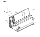
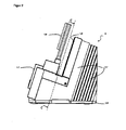
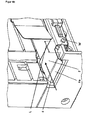
- FIG. 1 shows the basic structure of the balance according to the invention in front view.
- the conveyor belt according to the invention by the plexiglass (1.4) is covered.
- FIG. 4 shows an open representation of the balance according to the invention.
- the drive devices of the transport belt are in the following FIG. 5 again shown in detail.
- the motor shafts of the motors M1 and M2 and the associated toothed belts which accomplish the propulsion of the transport frame via a transmission.
- the weighing pan 1 with a length L1
- the weighing pan 2 with a length L2
- the spring plate F with a length L.
- the length L1 of the weighing pan 1 can be 240-340 mm, preferably about 331 mm.
- the length L2 of the weighing pan 2 can be 150-180 mm, preferably about 161 mm.
- the length L of the spring plate F can be 14-21 mm, preferably about 18 mm.
- FIG. 6 shows this arrangement again from another perspective.
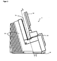
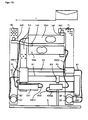
- FIG. 7 shows the basic structure of the balance according to the invention. To see is a perspective view of the arrangement of the electrical and mechanical assemblies of the dynamic balance from behind. The weighing sample runs in this illustration from right to left (in the direction of the arrow). Clearly visible is a plurality of recesses (A, shown only a few examples), in the basic construction consisting of frame and carrier, which reduce the mass according to the invention. The recesses in the carriers Tr1 and Tr2 are mounted vertically, so that they are not visible from the perspective shown. The two drive motors M1 and M2 are located near the bottom plate B.
- FIG. 8 shows further details of the device according to the invention from a different perspective, with particular representation of the electrical components.
- the transport direction of the goods from right to left (arrow) runs.
- the two ribbon cables which are arranged with the flat side parallel to the load cells or the bottom plate, can be seen here.
- the printed circuit board of the load cell 2 which ensures the transition of electrical signals in a round cable.
- the rivet joints (N), the stiffening elements (V) and the recesses (A) are clearly visible.
- FIG. 9 shows the measurement result of a measurement of disturbance forces as a function of the transport speed.
- the transport speed was gradually increased from about 200 to about 800 mm / s. It can be clearly seen that the measurement error hardly varies with a variation of the transport speed of 200 - approx. 720 mm / s. From about 740 mm / s occur clearly visible disturbances that distort the result in a way that it is no longer acceptable for the purpose of the invention. At a transport speed of 700 mm / s, however, the weighing can be done with sufficient accuracy.
- FIG. 10 shows the spring plate according to the invention attached.
- the running direction of the goods to be weighed is in the direction of the arrow (here from left to right).
- the attachment to the first shaft (W) of the first conveyor belt You can also see the angled part of the spring plate F a , which shows a bend of about 40 °. It can be seen, moreover, that by the spring plate according to the invention an extension of the Weighing the length L takes place, which starts at the bend and ends with the shaft.
- FIG. 11 shows the application of the filters according to the invention.
- the stop bands of the two notch filters are shown here by way of example at about 9 and at about 18 Hz.
- the blocking range of the low pass can be seen.
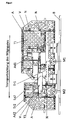
- FIG. 12 shows a schematic representation of the cable courses within the dynamic balance.
- a first round cable R1 electrically connects the first circuit board P1 to the first motor M1 and the first encoder E1.
- the first circuit board P1 is mounted on the first frame T1.
- the first round cable R1 starting from the first printed circuit board P1 serves to transmit the drive signals to the first motor M1 and to transmit the encoder signals from the first encoder E1 to the first printed circuit board P1. It is provided that the adapter Ad1 of the first frame T1 rests on the load introduction point La1 of the first balance beam Wb1.
- a second round cable R2 electrically connects the second circuit board P2 to the second motor M2 and the second encoder E2.
- the second circuit board P2 is mounted on the carrier Tr2.
- the second round cable R2 emanating from the second printed circuit board P2 serves to transmit the drive signals to the second motor M2 and to transmit the encoder signals from the second encoder E2 to the second printed circuit board P2.
- the adapter Ad2 of the second frame T2 rests on the one end of the carrier Tr2, the other end of the carrier Tr2 being mounted on a load introduction point La2 of the weighing beam Wb2.
- the first electronic measurement processing unit EV1 and the second circuit board P2 are mechanically connected to the carrier Tr2. From the output of the first electronic measured value processing unit EV1 is a shielded round cable KW12, which is electrically connected to the second circuit board P2.
- the second weighing beam Wb2 is replaced by a shielded round cable KW21, which is connected to the input of the second electronic measured value processing unit EV2.
- the second electronic measured value processing unit EV2 and a cable holder KH are mechanically connected to the base plate B and arranged in the region of the frame T1, preferably near the rear of the dynamic balance and in the process the frame T1.
- From the output of the second electronic measured value processing unit EV2 is a shielded round cable KW22, which is connected to an input of the common control unit GST.
- a first flat cable K1 is arranged with the flat side parallel to the bottom plate B, wherein via the first ribbon cable K1 both the transmission of the output-side drive signals of the common control unit GST to the second motor M2, as well as the transmission the encoder signals from the second encoder E2 and the transmission of the output signals of the electronic Meßwertakusaku EV1 to the inputs of the common control unit GST takes place.
- a second ribbon cable K2 is arranged with the flat side parallel to the bottom plate B.
- the first circuit board P1 is mechanically connected to the first frame T1. Via the second flat cable K2, the transmission of the drive signals to the first motor M1 and a transmission of the encoder signals from the first encoder E1 takes place.
- the first circuit board P1 serves to adapt the first round cable R1 to the second flat cable K2.
Landscapes
- Physics & Mathematics (AREA)
- General Physics & Mathematics (AREA)
- Mathematical Physics (AREA)
- Sorting Of Articles (AREA)
- Delivering By Means Of Belts And Rollers (AREA)
- Control Of Conveyors (AREA)
- Structure Of Belt Conveyors (AREA)
- Jigging Conveyors (AREA)
Applications Claiming Priority (2)
| Application Number | Priority Date | Filing Date | Title |
|---|---|---|---|
| DE202014004821 | 2014-06-16 | ||
| DE202015002361.4U DE202015002361U1 (de) | 2014-06-16 | 2015-03-30 | Verbesserungen an einer dynamischen Waage mit mehreren Wägeschalen |
Publications (3)
| Publication Number | Publication Date |
|---|---|
| EP2957874A2 true EP2957874A2 (fr) | 2015-12-23 |
| EP2957874A3 EP2957874A3 (fr) | 2016-03-16 |
| EP2957874B1 EP2957874B1 (fr) | 2019-11-20 |
Family
ID=53498172
Family Applications (1)
| Application Number | Title | Priority Date | Filing Date |
|---|---|---|---|
| EP15001769.7A Active EP2957874B1 (fr) | 2014-06-16 | 2015-06-16 | Ameliorations d'une balance dynamique ayant plusieurs coupelles de pesee |
Country Status (4)
| Country | Link |
|---|---|
| US (1) | US9778094B2 (fr) |
| EP (1) | EP2957874B1 (fr) |
| CA (2) | CA2894338C (fr) |
| DE (1) | DE202015002361U1 (fr) |
Families Citing this family (3)
| Publication number | Priority date | Publication date | Assignee | Title |
|---|---|---|---|---|
| DE102014211515A1 (de) * | 2014-06-16 | 2015-12-17 | Francotyp-Postalia Gmbh | Wiegeverfahren, Anordnung zur Durchführung des Wiegeverfahrens sowie ein entsprechendes Computerprogramm und ein entsprechendes computerlesbares Speichermedium |
| US10498762B1 (en) | 2015-10-22 | 2019-12-03 | Versafe Ltd. | Methods for hypertext markup language (HTML) input field obfuscation and devices thereof |
| US11658995B1 (en) | 2018-03-20 | 2023-05-23 | F5, Inc. | Methods for dynamically mitigating network attacks and devices thereof |
Citations (3)
| Publication number | Priority date | Publication date | Assignee | Title |
|---|---|---|---|---|
| EP0974819A2 (fr) | 1998-07-17 | 2000-01-26 | Francotyp-Postalia Aktiengesellschaft & Co. | Dispositif pour le pesage de courrier en mouvement |
| EP2017589A2 (fr) | 2007-07-02 | 2009-01-21 | Pitney Bowes, Inc. | Dispositif pour peser des articles de courrier |
| EP2520911A1 (fr) | 2011-05-02 | 2012-11-07 | Francotyp-Postalia GmbH | Balance dynamique dotée de plusieurs coupelles de pesée et procédé de fonctionnement de la balance dynamique |
Family Cites Families (26)
| Publication number | Priority date | Publication date | Assignee | Title |
|---|---|---|---|---|
| CA1071661A (fr) * | 1976-02-05 | 1980-02-12 | Walter R. Carnes | Balance a ressort a lames avec detecteur optique |
| JPS57144424A (en) * | 1981-03-03 | 1982-09-07 | Yamato Scale Co Ltd | High speed weighing device |
| US4814995A (en) * | 1982-03-29 | 1989-03-21 | Pitney Bowes Inc. | Postage value determining scale with recall and display of special fee entries |
| JPS6151524A (ja) * | 1984-08-20 | 1986-03-14 | Tokyo Electric Co Ltd | マルチレンジロ−ドセル秤 |
| JPS62133321A (ja) * | 1985-12-05 | 1987-06-16 | Yamato Scale Co Ltd | 計重コンベヤの動的計重値の補正装置 |
| JPH07118642B2 (ja) * | 1986-01-08 | 1995-12-18 | 株式会社東芝 | レベル変換回路 |
| JPH0621814B2 (ja) * | 1986-05-29 | 1994-03-23 | 大和製衡株式会社 | 計重装置の計重信号の濾波方法及び装置 |
| US4815547A (en) * | 1987-11-30 | 1989-03-28 | Toledo Scale Corporation | Load cell |
| US5130938A (en) * | 1989-11-29 | 1992-07-14 | Yamato Scale Company, Limited | Device and method for filtering weight indicative signal from weighing device |
| US5072799A (en) * | 1990-07-11 | 1991-12-17 | Pitney Bowes Inc. | Load cell supporting member and weighing scale incorporating the same |
| US5190117A (en) * | 1990-07-11 | 1993-03-02 | Pitney Bowes Inc. | Load cell supporting member and weighing scale incorporating the same |
| US5291422A (en) * | 1992-01-28 | 1994-03-01 | Sgi International | Broadband instrument for nondestructive measurement of material properties |
| US5623128A (en) * | 1994-03-01 | 1997-04-22 | Mettler-Toledo, Inc. | Load cell with modular calibration components |
| GB2287541B (en) * | 1994-03-07 | 1998-04-15 | Yamato Scale Co Ltd | Device and method for determining weighing conditions of dynamic weighing device |
| US5856637A (en) * | 1994-11-07 | 1999-01-05 | Vande Berg; David M. | Weighing scale for moving loads |
| DE19605015C1 (de) * | 1996-01-31 | 1997-03-06 | Francotyp Postalia Gmbh | Vorrichtung zum Bedrucken eines auf einer Kante stehenden Druckträgers |
| US5990422A (en) * | 1996-10-18 | 1999-11-23 | Shinko Denshi Company Limited | Apparatus for measuring weight and length of article |
| EP1056991A1 (fr) * | 1998-01-20 | 2000-12-06 | Marel HF. | Procede et dispositif de pesee |
| US6713689B2 (en) * | 2002-07-09 | 2004-03-30 | Pitney Bowes Inc. | System and method for weighing items such as mailpieces with varying accuracy |
| US6820873B2 (en) * | 2003-03-06 | 2004-11-23 | Pitney Bowes Inc. | Transport mechanism for a mailing machine |
| DE102005055755B4 (de) * | 2005-11-21 | 2019-12-12 | Wipotec Wiege- Und Positioniersysteme Gmbh | Vorrichtung zum Wiegen mit mehreren Wägezellen |
| US7279645B1 (en) * | 2006-05-12 | 2007-10-09 | Mettler-Toledo, Inc. | Multiple conveyor and scale weighing apparatus |
| US7687727B2 (en) * | 2007-09-13 | 2010-03-30 | Raf Technology, Inc. | Weigh on the fly |
| DE202007016722U1 (de) * | 2007-11-28 | 2008-02-07 | Wipotec Wiege- Und Positioniersysteme Gmbh | Vorrichtung für den Transport und das Wiegen von Briefen |
| US8178796B2 (en) * | 2009-12-17 | 2012-05-15 | Pitney Bowes Inc. | Mailing machine transport system including a guide to reduce the impact on the weighing device caused by the trailing edge of the mailpeice |
| US8148650B2 (en) * | 2009-12-17 | 2012-04-03 | Pitney Bowes Inc. | Mailing machine transport system with integral scale for weighing mail pieces where the contact force on the take away rollers is reduced to eliminate oscillations of the weighing platform |
-
2015
- 2015-03-30 DE DE202015002361.4U patent/DE202015002361U1/de not_active Expired - Lifetime
- 2015-06-08 US US14/733,189 patent/US9778094B2/en active Active
- 2015-06-16 EP EP15001769.7A patent/EP2957874B1/fr active Active
- 2015-06-16 CA CA2894338A patent/CA2894338C/fr active Active
- 2015-06-16 CA CA2984665A patent/CA2984665C/fr active Active
Patent Citations (4)
| Publication number | Priority date | Publication date | Assignee | Title |
|---|---|---|---|---|
| EP0974819A2 (fr) | 1998-07-17 | 2000-01-26 | Francotyp-Postalia Aktiengesellschaft & Co. | Dispositif pour le pesage de courrier en mouvement |
| EP0974819B1 (fr) | 1998-07-17 | 2005-11-30 | Francotyp-Postalia AG & Co. KG | Dispositif pour le pesage de courrier en mouvement |
| EP2017589A2 (fr) | 2007-07-02 | 2009-01-21 | Pitney Bowes, Inc. | Dispositif pour peser des articles de courrier |
| EP2520911A1 (fr) | 2011-05-02 | 2012-11-07 | Francotyp-Postalia GmbH | Balance dynamique dotée de plusieurs coupelles de pesée et procédé de fonctionnement de la balance dynamique |
Also Published As
| Publication number | Publication date |
|---|---|
| EP2957874A3 (fr) | 2016-03-16 |
| US20160018251A1 (en) | 2016-01-21 |
| CA2984665C (fr) | 2020-03-24 |
| EP2957874B1 (fr) | 2019-11-20 |
| CA2984665A1 (fr) | 2015-12-16 |
| CA2894338A1 (fr) | 2015-12-16 |
| CA2894338C (fr) | 2018-07-17 |
| DE202015002361U1 (de) | 2015-06-17 |
| US9778094B2 (en) | 2017-10-03 |
Similar Documents
| Publication | Publication Date | Title |
|---|---|---|
| EP2520911B1 (fr) | Dispositif de pesage dynamique dotée de plusieurs plateaux de pesage et procédé de fonctionnement de la balance dynamique | |
| DE19833767C2 (de) | Vorrichtung zum Wiegen von bewegtem Postgut | |
| DE202016106125U1 (de) | Dynamische Waage für auf der Seite liegend transportierte flache Güter | |
| DE69019724T2 (de) | Verbessertes Kontrollwiegegerät. | |
| EP2957874B1 (fr) | Ameliorations d'une balance dynamique ayant plusieurs coupelles de pesee | |
| DE102018129119A1 (de) | Fahrwerksaktuator für eine Hinterachslenkung | |
| DE102007040301B4 (de) | Verfahren und Vorrichtung zur dynamischen Kontrollwägung | |
| DE2740729C3 (de) | Ausgleichssystem für den Antrieb eines Walzgerüstes eines Kaltpilgerwalzwerkes | |
| DE69215055T2 (de) | Waage zur Schnellbestimmung von Gewichten | |
| EP2416133B1 (fr) | Dispositif de mesure de force et balance | |
| DE3534555A1 (de) | Vorrichtung zum transport und wiegen oder kontrollwiegen von gegenstaenden | |
| DE19609431C2 (de) | Verfahren zum Wägen und Etikettieren von Warenpackungen und Vorrichtung zur Durchführung des Verfahrens | |
| EP2865614A1 (fr) | Bâti pour une installation de tapis de transport | |
| EP0595438A2 (fr) | Installation de détermination de la qualité de bois de sciage | |
| EP1014050A1 (fr) | Procédé et dispositif pour contrôler une balance dynamique | |
| DE60307519T2 (de) | Vorrichtung zum dynamischen wiegen von postsendungen | |
| DE3318409C2 (de) | Verfahren zum Ermitteln des Gewichtes von kontinuierlich geförderten einstückigen Gütern und Kontrollwaage zur Durchführung des Verfahrens | |
| WO1999008079A1 (fr) | Procede et dispositif pour peser et etiqueter des emballages de marchandises | |
| EP3615898B1 (fr) | Étalonnage d'un dispositif de transport et de dosage | |
| EP3021093B1 (fr) | Bascule à courroie | |
| DE602006000386T2 (de) | Vorrichtung zur Breitenmessung mittels des Lichtdämpfungsunterschieds | |
| DE19922881C2 (de) | Vorrichtung zum Wiegen von bewegtem Postgut | |
| DE202008004480U1 (de) | Halteeinrichtung für Drehimpulsgeber | |
| DE2205184C2 (de) | Wägezellenwaage mit einem an Lenkern aufgehängten Lastträger | |
| DE2641591C3 (de) | Dosierbandwaage |
Legal Events
| Date | Code | Title | Description |
|---|---|---|---|
| PUAI | Public reference made under article 153(3) epc to a published international application that has entered the european phase |
Free format text: ORIGINAL CODE: 0009012 |
|
| AK | Designated contracting states |
Kind code of ref document: A2 Designated state(s): AL AT BE BG CH CY CZ DE DK EE ES FI FR GB GR HR HU IE IS IT LI LT LU LV MC MK MT NL NO PL PT RO RS SE SI SK SM TR |
|
| AX | Request for extension of the european patent |
Extension state: BA ME |
|
| PUAL | Search report despatched |
Free format text: ORIGINAL CODE: 0009013 |
|
| AK | Designated contracting states |
Kind code of ref document: A3 Designated state(s): AL AT BE BG CH CY CZ DE DK EE ES FI FR GB GR HR HU IE IS IT LI LT LU LV MC MK MT NL NO PL PT RO RS SE SI SK SM TR |
|
| AX | Request for extension of the european patent |
Extension state: BA ME |
|
| RIC1 | Information provided on ipc code assigned before grant |
Ipc: G01G 19/00 20060101AFI20160205BHEP |
|
| 17P | Request for examination filed |
Effective date: 20160908 |
|
| RBV | Designated contracting states (corrected) |
Designated state(s): AL AT BE BG CH CY CZ DE DK EE ES FI FR GB GR HR HU IE IS IT LI LT LU LV MC MK MT NL NO PL PT RO RS SE SI SK SM TR |
|
| GRAP | Despatch of communication of intention to grant a patent |
Free format text: ORIGINAL CODE: EPIDOSNIGR1 |
|
| STAA | Information on the status of an ep patent application or granted ep patent |
Free format text: STATUS: GRANT OF PATENT IS INTENDED |
|
| INTG | Intention to grant announced |
Effective date: 20190726 |
|
| GRAA | (expected) grant |
Free format text: ORIGINAL CODE: 0009210 |
|
| STAA | Information on the status of an ep patent application or granted ep patent |
Free format text: STATUS: THE PATENT HAS BEEN GRANTED |
|
| GRAS | Grant fee paid |
Free format text: ORIGINAL CODE: EPIDOSNIGR3 |
|
| AK | Designated contracting states |
Kind code of ref document: B1 Designated state(s): AL AT BE BG CH CY CZ DE DK EE ES FI FR GB GR HR HU IE IS IT LI LT LU LV MC MK MT NL NO PL PT RO RS SE SI SK SM TR |
|
| REG | Reference to a national code |
Ref country code: GB Ref legal event code: FG4D Free format text: NOT ENGLISH |
|
| REG | Reference to a national code |
Ref country code: CH Ref legal event code: EP |
|
| REG | Reference to a national code |
Ref country code: IE Ref legal event code: FG4D Free format text: LANGUAGE OF EP DOCUMENT: GERMAN |
|
| REG | Reference to a national code |
Ref country code: DE Ref legal event code: R096 Ref document number: 502015010957 Country of ref document: DE |
|
| REG | Reference to a national code |
Ref country code: CH Ref legal event code: NV Representative=s name: BOVARD AG PATENT- UND MARKENANWAELTE, CH |
|
| REG | Reference to a national code |
Ref country code: AT Ref legal event code: REF Ref document number: 1204708 Country of ref document: AT Kind code of ref document: T Effective date: 20191215 |
|
| REG | Reference to a national code |
Ref country code: NL Ref legal event code: FP |
|
| REG | Reference to a national code |
Ref country code: SE Ref legal event code: TRGR |
|
| REG | Reference to a national code |
Ref country code: LT Ref legal event code: MG4D |
|
| PG25 | Lapsed in a contracting state [announced via postgrant information from national office to epo] |
Ref country code: NO Free format text: LAPSE BECAUSE OF FAILURE TO SUBMIT A TRANSLATION OF THE DESCRIPTION OR TO PAY THE FEE WITHIN THE PRESCRIBED TIME-LIMIT Effective date: 20200220 Ref country code: LV Free format text: LAPSE BECAUSE OF FAILURE TO SUBMIT A TRANSLATION OF THE DESCRIPTION OR TO PAY THE FEE WITHIN THE PRESCRIBED TIME-LIMIT Effective date: 20191120 Ref country code: LT Free format text: LAPSE BECAUSE OF FAILURE TO SUBMIT A TRANSLATION OF THE DESCRIPTION OR TO PAY THE FEE WITHIN THE PRESCRIBED TIME-LIMIT Effective date: 20191120 Ref country code: GR Free format text: LAPSE BECAUSE OF FAILURE TO SUBMIT A TRANSLATION OF THE DESCRIPTION OR TO PAY THE FEE WITHIN THE PRESCRIBED TIME-LIMIT Effective date: 20200221 Ref country code: BG Free format text: LAPSE BECAUSE OF FAILURE TO SUBMIT A TRANSLATION OF THE DESCRIPTION OR TO PAY THE FEE WITHIN THE PRESCRIBED TIME-LIMIT Effective date: 20200220 Ref country code: FI Free format text: LAPSE BECAUSE OF FAILURE TO SUBMIT A TRANSLATION OF THE DESCRIPTION OR TO PAY THE FEE WITHIN THE PRESCRIBED TIME-LIMIT Effective date: 20191120 |
|
| PG25 | Lapsed in a contracting state [announced via postgrant information from national office to epo] |
Ref country code: HR Free format text: LAPSE BECAUSE OF FAILURE TO SUBMIT A TRANSLATION OF THE DESCRIPTION OR TO PAY THE FEE WITHIN THE PRESCRIBED TIME-LIMIT Effective date: 20191120 Ref country code: RS Free format text: LAPSE BECAUSE OF FAILURE TO SUBMIT A TRANSLATION OF THE DESCRIPTION OR TO PAY THE FEE WITHIN THE PRESCRIBED TIME-LIMIT Effective date: 20191120 Ref country code: IS Free format text: LAPSE BECAUSE OF FAILURE TO SUBMIT A TRANSLATION OF THE DESCRIPTION OR TO PAY THE FEE WITHIN THE PRESCRIBED TIME-LIMIT Effective date: 20200320 |
|
| PG25 | Lapsed in a contracting state [announced via postgrant information from national office to epo] |
Ref country code: AL Free format text: LAPSE BECAUSE OF FAILURE TO SUBMIT A TRANSLATION OF THE DESCRIPTION OR TO PAY THE FEE WITHIN THE PRESCRIBED TIME-LIMIT Effective date: 20191120 |
|
| PG25 | Lapsed in a contracting state [announced via postgrant information from national office to epo] |
Ref country code: PT Free format text: LAPSE BECAUSE OF FAILURE TO SUBMIT A TRANSLATION OF THE DESCRIPTION OR TO PAY THE FEE WITHIN THE PRESCRIBED TIME-LIMIT Effective date: 20200412 Ref country code: DK Free format text: LAPSE BECAUSE OF FAILURE TO SUBMIT A TRANSLATION OF THE DESCRIPTION OR TO PAY THE FEE WITHIN THE PRESCRIBED TIME-LIMIT Effective date: 20191120 Ref country code: EE Free format text: LAPSE BECAUSE OF FAILURE TO SUBMIT A TRANSLATION OF THE DESCRIPTION OR TO PAY THE FEE WITHIN THE PRESCRIBED TIME-LIMIT Effective date: 20191120 Ref country code: CZ Free format text: LAPSE BECAUSE OF FAILURE TO SUBMIT A TRANSLATION OF THE DESCRIPTION OR TO PAY THE FEE WITHIN THE PRESCRIBED TIME-LIMIT Effective date: 20191120 Ref country code: RO Free format text: LAPSE BECAUSE OF FAILURE TO SUBMIT A TRANSLATION OF THE DESCRIPTION OR TO PAY THE FEE WITHIN THE PRESCRIBED TIME-LIMIT Effective date: 20191120 Ref country code: ES Free format text: LAPSE BECAUSE OF FAILURE TO SUBMIT A TRANSLATION OF THE DESCRIPTION OR TO PAY THE FEE WITHIN THE PRESCRIBED TIME-LIMIT Effective date: 20191120 |
|
| REG | Reference to a national code |
Ref country code: DE Ref legal event code: R097 Ref document number: 502015010957 Country of ref document: DE |
|
| PG25 | Lapsed in a contracting state [announced via postgrant information from national office to epo] |
Ref country code: SM Free format text: LAPSE BECAUSE OF FAILURE TO SUBMIT A TRANSLATION OF THE DESCRIPTION OR TO PAY THE FEE WITHIN THE PRESCRIBED TIME-LIMIT Effective date: 20191120 Ref country code: SK Free format text: LAPSE BECAUSE OF FAILURE TO SUBMIT A TRANSLATION OF THE DESCRIPTION OR TO PAY THE FEE WITHIN THE PRESCRIBED TIME-LIMIT Effective date: 20191120 |
|
| PLBE | No opposition filed within time limit |
Free format text: ORIGINAL CODE: 0009261 |
|
| STAA | Information on the status of an ep patent application or granted ep patent |
Free format text: STATUS: NO OPPOSITION FILED WITHIN TIME LIMIT |
|
| 26N | No opposition filed |
Effective date: 20200821 |
|
| PG25 | Lapsed in a contracting state [announced via postgrant information from national office to epo] |
Ref country code: SI Free format text: LAPSE BECAUSE OF FAILURE TO SUBMIT A TRANSLATION OF THE DESCRIPTION OR TO PAY THE FEE WITHIN THE PRESCRIBED TIME-LIMIT Effective date: 20191120 Ref country code: PL Free format text: LAPSE BECAUSE OF FAILURE TO SUBMIT A TRANSLATION OF THE DESCRIPTION OR TO PAY THE FEE WITHIN THE PRESCRIBED TIME-LIMIT Effective date: 20191120 |
|
| PG25 | Lapsed in a contracting state [announced via postgrant information from national office to epo] |
Ref country code: MC Free format text: LAPSE BECAUSE OF FAILURE TO SUBMIT A TRANSLATION OF THE DESCRIPTION OR TO PAY THE FEE WITHIN THE PRESCRIBED TIME-LIMIT Effective date: 20191120 |
|
| PG25 | Lapsed in a contracting state [announced via postgrant information from national office to epo] |
Ref country code: LU Free format text: LAPSE BECAUSE OF NON-PAYMENT OF DUE FEES Effective date: 20200616 |
|
| REG | Reference to a national code |
Ref country code: BE Ref legal event code: MM Effective date: 20200630 |
|
| PG25 | Lapsed in a contracting state [announced via postgrant information from national office to epo] |
Ref country code: IE Free format text: LAPSE BECAUSE OF NON-PAYMENT OF DUE FEES Effective date: 20200616 |
|
| PG25 | Lapsed in a contracting state [announced via postgrant information from national office to epo] |
Ref country code: BE Free format text: LAPSE BECAUSE OF NON-PAYMENT OF DUE FEES Effective date: 20200630 |
|
| PG25 | Lapsed in a contracting state [announced via postgrant information from national office to epo] |
Ref country code: TR Free format text: LAPSE BECAUSE OF FAILURE TO SUBMIT A TRANSLATION OF THE DESCRIPTION OR TO PAY THE FEE WITHIN THE PRESCRIBED TIME-LIMIT Effective date: 20191120 Ref country code: MT Free format text: LAPSE BECAUSE OF FAILURE TO SUBMIT A TRANSLATION OF THE DESCRIPTION OR TO PAY THE FEE WITHIN THE PRESCRIBED TIME-LIMIT Effective date: 20191120 Ref country code: CY Free format text: LAPSE BECAUSE OF FAILURE TO SUBMIT A TRANSLATION OF THE DESCRIPTION OR TO PAY THE FEE WITHIN THE PRESCRIBED TIME-LIMIT Effective date: 20191120 |
|
| PG25 | Lapsed in a contracting state [announced via postgrant information from national office to epo] |
Ref country code: MK Free format text: LAPSE BECAUSE OF FAILURE TO SUBMIT A TRANSLATION OF THE DESCRIPTION OR TO PAY THE FEE WITHIN THE PRESCRIBED TIME-LIMIT Effective date: 20191120 |
|
| P01 | Opt-out of the competence of the unified patent court (upc) registered |
Effective date: 20230807 |
|
| REG | Reference to a national code |
Ref country code: DE Ref legal event code: R082 Ref document number: 502015010957 Country of ref document: DE Representative=s name: GULDE & PARTNER PATENT- UND RECHTSANWALTSKANZL, DE |
|
| PGFP | Annual fee paid to national office [announced via postgrant information from national office to epo] |
Ref country code: DE Payment date: 20250606 Year of fee payment: 11 |
|
| PGFP | Annual fee paid to national office [announced via postgrant information from national office to epo] |
Ref country code: GB Payment date: 20250618 Year of fee payment: 11 |
|
| PGFP | Annual fee paid to national office [announced via postgrant information from national office to epo] |
Ref country code: NL Payment date: 20250618 Year of fee payment: 11 |
|
| PGFP | Annual fee paid to national office [announced via postgrant information from national office to epo] |
Ref country code: FR Payment date: 20250625 Year of fee payment: 11 |
|
| PGFP | Annual fee paid to national office [announced via postgrant information from national office to epo] |
Ref country code: AT Payment date: 20250620 Year of fee payment: 11 |
|
| PGFP | Annual fee paid to national office [announced via postgrant information from national office to epo] |
Ref country code: SE Payment date: 20250618 Year of fee payment: 11 |
|
| PGFP | Annual fee paid to national office [announced via postgrant information from national office to epo] |
Ref country code: IT Payment date: 20250624 Year of fee payment: 11 |
|
| PGFP | Annual fee paid to national office [announced via postgrant information from national office to epo] |
Ref country code: CH Payment date: 20250701 Year of fee payment: 11 |