EP2957894A1 - Système d'analyse confocal à écran diffusant - Google Patents
Système d'analyse confocal à écran diffusant Download PDFInfo
- Publication number
- EP2957894A1 EP2957894A1 EP14172657.0A EP14172657A EP2957894A1 EP 2957894 A1 EP2957894 A1 EP 2957894A1 EP 14172657 A EP14172657 A EP 14172657A EP 2957894 A1 EP2957894 A1 EP 2957894A1
- Authority
- EP
- European Patent Office
- Prior art keywords
- measuring cell
- analysis system
- receiving position
- scattered light
- focus
- Prior art date
- Legal status (The legal status is an assumption and is not a legal conclusion. Google has not performed a legal analysis and makes no representation as to the accuracy of the status listed.)
- Withdrawn
Links
Images
Classifications
-
- G—PHYSICS
- G01—MEASURING; TESTING
- G01N—INVESTIGATING OR ANALYSING MATERIALS BY DETERMINING THEIR CHEMICAL OR PHYSICAL PROPERTIES
- G01N21/00—Investigating or analysing materials by the use of optical means, i.e. using sub-millimetre waves, infrared, visible or ultraviolet light
- G01N21/17—Systems in which incident light is modified in accordance with the properties of the material investigated
- G01N21/47—Scattering, i.e. diffuse reflection
- G01N21/49—Scattering, i.e. diffuse reflection within a body or fluid
- G01N21/51—Scattering, i.e. diffuse reflection within a body or fluid inside a container, e.g. in an ampoule
-
- G—PHYSICS
- G01—MEASURING; TESTING
- G01J—MEASUREMENT OF INTENSITY, VELOCITY, SPECTRAL CONTENT, POLARISATION, PHASE OR PULSE CHARACTERISTICS OF INFRARED, VISIBLE OR ULTRAVIOLET LIGHT; COLORIMETRY; RADIATION PYROMETRY
- G01J3/00—Spectrometry; Spectrophotometry; Monochromators; Measuring colours
- G01J3/02—Details
- G01J3/0205—Optical elements not provided otherwise, e.g. optical manifolds, diffusers, windows
- G01J3/0208—Optical elements not provided otherwise, e.g. optical manifolds, diffusers, windows using focussing or collimating elements, e.g. lenses or mirrors; performing aberration correction
-
- G—PHYSICS
- G01—MEASURING; TESTING
- G01J—MEASUREMENT OF INTENSITY, VELOCITY, SPECTRAL CONTENT, POLARISATION, PHASE OR PULSE CHARACTERISTICS OF INFRARED, VISIBLE OR ULTRAVIOLET LIGHT; COLORIMETRY; RADIATION PYROMETRY
- G01J3/00—Spectrometry; Spectrophotometry; Monochromators; Measuring colours
- G01J3/28—Investigating the spectrum
- G01J3/42—Absorption spectrometry; Double beam spectrometry; Flicker spectrometry; Reflection spectrometry
-
- G—PHYSICS
- G01—MEASURING; TESTING
- G01J—MEASUREMENT OF INTENSITY, VELOCITY, SPECTRAL CONTENT, POLARISATION, PHASE OR PULSE CHARACTERISTICS OF INFRARED, VISIBLE OR ULTRAVIOLET LIGHT; COLORIMETRY; RADIATION PYROMETRY
- G01J3/00—Spectrometry; Spectrophotometry; Monochromators; Measuring colours
- G01J3/28—Investigating the spectrum
- G01J3/44—Raman spectrometry; Scattering spectrometry ; Fluorescence spectrometry
-
- G—PHYSICS
- G01—MEASURING; TESTING
- G01J—MEASUREMENT OF INTENSITY, VELOCITY, SPECTRAL CONTENT, POLARISATION, PHASE OR PULSE CHARACTERISTICS OF INFRARED, VISIBLE OR ULTRAVIOLET LIGHT; COLORIMETRY; RADIATION PYROMETRY
- G01J3/00—Spectrometry; Spectrophotometry; Monochromators; Measuring colours
- G01J3/28—Investigating the spectrum
- G01J3/44—Raman spectrometry; Scattering spectrometry ; Fluorescence spectrometry
- G01J3/4412—Scattering spectrometry
-
- G—PHYSICS
- G01—MEASURING; TESTING
- G01N—INVESTIGATING OR ANALYSING MATERIALS BY DETERMINING THEIR CHEMICAL OR PHYSICAL PROPERTIES
- G01N21/00—Investigating or analysing materials by the use of optical means, i.e. using sub-millimetre waves, infrared, visible or ultraviolet light
- G01N21/17—Systems in which incident light is modified in accordance with the properties of the material investigated
- G01N21/47—Scattering, i.e. diffuse reflection
- G01N2021/4704—Angular selective
- G01N2021/4707—Forward scatter; Low angle scatter
-
- G—PHYSICS
- G01—MEASURING; TESTING
- G01N—INVESTIGATING OR ANALYSING MATERIALS BY DETERMINING THEIR CHEMICAL OR PHYSICAL PROPERTIES
- G01N2201/00—Features of devices classified in G01N21/00
- G01N2201/06—Illumination; Optics
- G01N2201/064—Stray light conditioning
- G01N2201/0648—Shutters
Definitions
- the invention relates to a suitable for an analyzer, confocal analysis system with a light source, a receiving position for a measuring cell and a photodetector, which are arranged such that an outgoing light beam from the light source strikes the photodetector through the measuring cell.
- Today's analyzers are capable of performing a variety of detection reactions and analyzes on a sample.
- various devices for the spatial transfer of measuring cells, reaction vessels and reagent containers are required, such.
- the devices include a control unit, which is capable of using the appropriate software to plan the work steps for the desired analyzes largely independent and work off.
- modern analyzers can be equipped with a scattered light analysis system.
- concentration of finely divided, colloidal particles in liquids or gases can be determined quantitatively.
- the primary beam leaves the suspension unscrewed, and another part is scattered sideways to the incoming beam.
- this laterally emerging scattered light is measured.
- Nephelometry is used primarily for the quantitative or qualitative detection of analytes, for example proteins, which preferably are obtained by means of a specific binding reaction between specific binding partners, e.g. by antigen-antibody binding.
- a nephelometry system usually comprises at least one means for generating a beam which comprises a light source and at least one photodetector and at least one receiving position for a measuring cell.
- the photodetector may be disposed laterally of the light beam emitted from the light source to detect the scattered light at an angle of 90 ° to the direction of the light beam emitted from the light source.
- the intensity of the scattered light which is scattered at 90 ° to the direction of the light beam emitted from the light source may be relatively low, and the influence of the measurement by the non-scattered part of the light beam emitted by the light source, which is called a primary beam, is relatively low.
- the light source, receiving position and photodetector may be arranged such that the photodetector detects the scattered light at angles or angular ranges about the propagation direction of the light beam emitted from the light source in which the intensity of the scattered light is relatively high.
- the photodetector not only reaches the scattered light, but also the primary beam.
- the scattered part of the light is to contribute to the measurement result and light of the primary beam, which hits the detector, ultimately only leads to a deterioration of the signal-to-noise ratio, optimizing the measurement result as complete as possible suppression of the primary beam is required.
- optical apertures are used. These are by means of thin fasteners such.
- An important role in further optimizing the measurement result and increasing the signal-to-noise ratio is that signal from a defined, limited scattering volume within the sample should always be directed to the detector, measured and evaluated. Due to properties of the measuring cell, such as, for example, curved surfaces, scratches, other damage, stress birefringence, in particular in the case of e.g. made of polystyrene plastic measuring cells, scattering in the material of the measuring cell or inaccuracies in the positioning of the measuring cell relative to the beam path can cause effects that disturb the measurement signal. Inaccuracies in the positioning of the measuring cell relative to the beam path occur particularly in scattered light analysis systems, in which the measuring cell and the means for generating a beam during the measurement are moved relative to each other. Disturbing effects, which are caused by the measuring cell, are as far as possible to be separated from the signal from the mentioned scattering volume of the sample.
- measuring cells which are designed, for example, as highly precise plastic bodies with flat surfaces.
- the above-mentioned parasitic effects occur only to a comparatively small extent, so that the measurements are not significantly influenced thereby.
- such measuring cells are associated with relatively high costs.
- Non-circular cylindrical measuring cell geometries are much more difficult to process in machines because of the directional dependence.
- an improved Stray light analysis system for an analyzer can be achieved if the light scattered in the region of a focus of a beam within a sample confocal is imaged onto the plane of a space-filtering aperture, which signals from the scattering volume in the region of the focus of the beam within the sample of interference by disturbing effects of the measuring cell are caused, disconnected.
- the present invention is a scattered light analysis system having at least one means for generating a beam, at least one receiving position for a measuring cell, at least one means for focusing a beam, at least one aperture with a defined opening and at least one photodetector, wherein the means for generating a beam generates a convergent in at least one direction perpendicular to the optical axis beam and wherein the means for generating a beam, the receiving position for a measuring cell, the means for focusing a beam, the diaphragm and the Photo detector are arranged such that the convergent beam forms a first focus in a receiving position in the measuring cell and after passing through a arranged in the receiving position measuring cell at least partially meets the means for focusing a beam and wherein the beam after interaction with the means for focusing the beam forms a second focus and wherein the aperture of the aperture is positioned in the region of the second focus, and then at least partially meets the beam on the photodetector.
- the confocal scattered light analysis system according to the invention is a nephelometer for scattered light measurement.
- a “nephelometer” or “nephelometry system” is understood to mean a measuring unit which has at least one light source and at least one light detector and which is designed to allow the intensity of the light scattered in a sample to be measured.
- the arrangement of light source and light detector is selected so that the scattered light can be measured, that of macromolecules to be detected in the sample, for example of particle aggregates, due to a Analyte-dependent reaction in a reaction mixture arise, is scattered.
- the beam forms a focus in two mutually perpendicular directions perpendicular to the optical axis in a measuring cell arranged in the receiving position.
- a defined volume from the area of the focus is confocally imaged onto at least one photodetector.
- the convergent beam and the optical axis subtend an angle of from 2 to 45 degrees, preferably from 5 to 25 degrees, most preferably from 5 to 15, in at least one region between the means for generating a beam and the receiving position for a measuring cell Degrees.
- These preferred angles or angular ranges also depend, for example, on requirements of the product to be measured, such as, for example, Size and shape of the particles, their refractive index, surface textures and / or coagulation behavior.
- the optical properties and the geometry, including the size of the measuring cell must also be taken into account.
- the means for generating a beam comprises a light source and a lens, preferably a light source and a cylindrical lens.
- the lens is preferably arranged between the light source and the recording position for the measuring cell.
- the means for generating a beam comprises a light source, a first lens or a first lens system, a diaphragm with an aperture and a second lens or a second lens system.
- the lens is a converging lens or a lens.
- the converging lens generates a focus of the radiation beam, which preferably lies in the center of the cross section of a measuring cell arranged in the receiving position. This has the advantage that the selected scattering volume is in the region of the center of the cross section of the measuring cell and influences of the measuring cell on the scattering volume within the sample are further reduced.
- a light beam or light rays are also called bundles of rays.
- the scattered light analysis system is a centered system in which the optical axes of the optical elements coincide.
- the beam propagates along the optical axis.
- the optical axis preferably lies in the region of the center of the cross section of the radiation beam.
- the light source comprises at least one laser, a light emitting diode (LED), an incandescent lamp and / or a gas discharge lamp.
- LED light emitting diode
- the light source comprises at least one laser diode.
- a coherent and collimated light beam can be generated in a particularly simple manner, which has particularly advantageous properties for nephelometry.
- the light beam has a low divergence and therefore experiences comparatively little widening over the running distance.
- primary and scattered light are in the Photo detector particularly well distinguishable from each other. This also applies after scattering, bundling or deflection of the light beam by means of lenses and mirrors.
- At least one laser diode as a light source makes it possible in a particularly simple embodiment to arrange the stop stop such that the entire primary beam of the laser diode strikes the stop stop. As a result, only scattered light is picked up by the photodetector and used for the measurement.
- the light detector is preferably a photodiode which converts visible light, in some embodiments also IR or UV light, into an electrical current or voltage through the internal photoelectric effect.
- the light detector is a CCD sensor.
- CCD sensors consist of a matrix or a row of photosensitive photodiodes. If measurements are to be carried out at different wavelengths, each element of the CCD sensor can serve as a photodetector, which considerably simplifies the apparatus design.
- the light detector is a photocell, a silicon photodetector, an avalanche photodetector or a photomultiplier.
- the light source emits light having a wavelength between 200 nm and 1400 nm. In a preferred embodiment, the emits Light source light with a wavelength between 300 and 1100 nm.
- the scattered-light analysis system may furthermore have filters, optical elements (for example lenses for constructing a condenser), control electronics, evaluation and read-out electronics and / or a voltage supply.
- filters for example lenses for constructing a condenser
- control electronics for example lenses for constructing a condenser
- evaluation and read-out electronics and / or a voltage supply.
- a stop stop is positioned between the receiving position for the measuring cell and the photodetector such that the beam at least partially strikes the stop stop.
- the non-scattered part of the radiation beam strikes at least partially, preferably completely, the stop diaphragm.
- the stop stop is formed in the shape of an oval or a circle.
- a scattered-light analysis system according to the invention preferably further comprises at least one holder for fastening the stop-stop.
- the scattered light analysis system comprises at least two receiving positions for each measuring cell, wherein at least the at least one means for generating a beam, the at least one means for focusing a beam, the at least one aperture with a defined opening and the at least one photodetector relative to the at least two receiving positions are movable, preferably movable on a circular path.
- the receiving positions for the measuring cells are arranged stationary. For example, vibrations and centripetal forces which can influence the sample in the measuring cell can be avoided. Furthermore, it is also easier to access the samples during measurements or between measurements.
- the at least two receiving positions for each measuring cell are arranged in a circular path, preferably in at least two concentric circular paths. This has the advantage that a larger number of receiving positions can be arranged per unit area. Furthermore, this can further increase the sample throughput.
- the receiving position for receiving a measuring cell with oval, round, rectangular, hemispherical, and / or polygonal cross sections is suitable. This is advantageous since, depending on the requirements of the scattered light analysis system and / or its measuring properties, measuring cells with certain cross sections can be advantageous.
- Another preferred embodiment of the scattered light analysis system comprises at least one measuring cell with rectangular, polygonal, oval and / or round cross sections.
- the measuring cell may be, for example, a cuvette, which may consist of glass, plastic or quartz glass. Also flow cuvettes can be used as a measuring cell in the scattered light analysis system according to the invention.
- Another object of the invention is an analysis device which comprises a scattered light analysis system according to the invention.
- the invention also includes methods of determining the concentration, amount and / or activity of at least one analyte in a sample, mixing the sample with one or more reagents to form a reaction, and changing the absorbance and / or the change in the intensity of the scattered light is determined with a scattered light measuring system according to the invention or with an analyzer according to the invention, wherein the change in the absorption and / or the change in the intensity of the scattered light correlates with the concentration, amount and / or activity of the analyte.
- sample is to be understood as meaning the material that presumably contains the substance to be detected (the analyte).
- the term sample in particular comprises biological fluids of humans or animals such as e.g. Blood, plasma, serum, sputum, exudate, bronchoalveolar lavage, lymphatic fluid, synovial fluid, seminal fluid, vaginal mucus, feces, urine, cerebrospinal fluid, but also e.g. Tissue or cell culture samples prepared by homogenization or cell lysis for the nephelometric determination.
- biological fluids of humans or animals such as e.g. Blood, plasma, serum, sputum, exudate, bronchoalveolar lavage, lymphatic fluid, synovial fluid, seminal fluid, vaginal mucus, feces, urine, cerebrospinal fluid, but also e.g. Tissue or cell culture samples prepared by homogenization or cell lysis for the nephelometric determination.
- Quantitative detection measures the amount, concentration or activity of the analyte in the sample.
- quantitative detection also includes semiquantitative methods which capture only the approximate amount, concentration or activity of the analyte in the sample or only to a relative amount, concentration or activity indication.
- qualitative detection is meant detecting the presence of the analyte in the sample at all, or indicating that the amount, concentration or activity of the analyte in the sample is below or above a certain threshold (s).
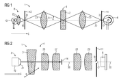
- the scattered light analysis systems (1) according to the 1 and FIG. 2 show various preferred embodiments of a scattered light analysis system according to the invention.
- objects of the various preferred embodiments can be combined with one another in any desired way in order to obtain further embodiments according to the invention.
- the scattered light analysis system (1) according to FIG. 1 is embedded in an analyzer, not shown in detail, which is designed to perform a variety of analyzes of samples.
- the automatic analyzer comprises a plurality of transport devices, not shown, as well as a control unit for the automated analysis of the analyzes.
- the scattered light analysis system (1) comprises a receiving position (4) for a measuring cell (2). It further comprises a photodetector (6) capable of accurately measuring the amount of light incident on a given surface and means (8) for generating a beam comprising a light source (10) and an upstream lens (21), a diaphragm (12 ) with an aperture (15) and a further lens (23).
- the beam generated by the laser diode is directed in the direction indicated by an arrow C and strikes the lens (21) and forms a focus (33) in the region of an aperture (15) in a diaphragm (12).
- the beam partially passes through the aperture (15) and strikes a further lens (23), which produces a focus (35) in the measuring cell (2) in the receiving position (4).
- the means (8) for generating a beam thus emits a convergent laser light beam directed in the direction C indicated by an arrow.
- the convergent beam bundles an angle (51) between the lens (23) and the receiving position (4) with the optical axis (30).
- the beam After emerging from the measuring cell (2), the beam is divergent and strikes a lens (25), which produces a focus (37) of the beam in the region of an aperture (17) in a diaphragm (14). The beam partially passes through the aperture (17) and strikes the photodetector (6).
- the beam is scattered, so that only a part unscrewed leaves the measuring cell (2). This part is the primary beam. Another part of the light is scattered, which generally leads to a widening of the beam.
- the photodetector determines, for example, the strength of the incident light.
- the lenses (21, 23, 25) are designed as converging lenses.
- the function of the diaphragm (14) with the diaphragm opening (17) can also be fulfilled by a suitable photodetector (6).
- the photodetector (6) may have an aperture which acts as a diaphragm (14) with the diaphragm opening (17), or the active, photosensitive surface of the detector itself may, due to its size and shape as an aperture (17) with the diaphragm opening (17 ) Act.
- the photodetector (6) is connected to the aforementioned control unit and allows an evaluation of the Scattered light. All components described may be housed in a housing (not shown).
- the scattered light analysis system (1) according to FIG. 2 is also embedded in an analyzer, not shown in detail, which is designed to perform a variety of analyzes of samples.
- the automatic analyzer comprises a plurality of pipetting devices and transport devices, not shown, as well as a control unit for the automated analysis of the analyzes.
- the scattered light analysis system (1) comprises a receiving position (4) for a measuring cell (2) which is movable in the direction B.
- the directions B and C are perpendicular to each other.
- the scattered-light analysis system (1) further comprises a photodetector (6) capable of accurately measuring the amount of light incident on a given surface and means (8) for generating a beam comprising a laser diode (10) and an upstream lens (21) / or a lens system (not shown) and a shutter (not shown).
- the means (8) for generating a beam thus emits a convergent laser light beam. This is directed in the direction indicated by an arrow C direction.
- the beam forms a focus (35) in the measuring cell (2) in the receiving position (4).
- the measuring cell (2) has the shape of a truncated cone.
- the measuring cell (2) for example, in the form of a straight circular cylinder.
- the beam After emerging from the measuring cell (2), the beam is divergent and then impinges on a lens (26) and a lens (27) having a focus (39) of the beam in the region between a stop stop (16) and another lens (28 ) train. After exiting the lens (27), the beam partially impinges on the stop stop (16) and is absorbed and / or reflected by the latter and does not hit on the photodetector (6). This part of the beam is essentially the unscattered primary beam. Another part of the beam forms a focus (39) after exiting the lens (27) and impinges divergently on a lens (28) and on a lens (29) which has a focus (37) in an aperture (17) in FIG create a diaphragm (14). The beam passes partially through the aperture (17) and impinges on the photodetector (6) and partly on the aperture (14) and is absorbed and / or reflected by the latter and does not strike the photodetector (6).
- the stop stop (16) is located between the lens (27) and the focus (39). Alternatively, the stop stop (16) is in close spatial proximity to the lens (27) or in a plane perpendicular to the optical axis (30) in the region of the focus (39).
- the focus (35) in the measuring cell (2), which is arranged in the receiving position (4) and the focus (37) of the diaphragm opening (17) in the diaphragm (14) are arranged confocally.
- the beam is scattered, so that only a part unscrewed leaves the measuring cell (2). This part is the primary beam. Another part of the light is scattered, which generally leads to a widening of the beam.
- the photodetector determines, for example, the strength of the incident light.
- the lenses (21, 26, 27, 28, 29) are designed as converging lenses.
- the photodetector (6) is connected to the aforementioned control unit and allows an evaluation of the scattering of the beam emitted by the means for generating a beam (8). All components described may be housed in a housing (not shown).
- the position of the pixel in the confocal image plane changes only relatively little.
- the recording position (4) with a measuring cell (2) is displaced along direction B by, for example, 1 mm from the central position relative to the optical axis (30)
- the pixel moves in the confocal image plane (plane of the diaphragm 14) or on the photodetector (FIG. 6) by less than 10 microns.
Landscapes
- Physics & Mathematics (AREA)
- Spectroscopy & Molecular Physics (AREA)
- General Physics & Mathematics (AREA)
- Health & Medical Sciences (AREA)
- Life Sciences & Earth Sciences (AREA)
- Chemical & Material Sciences (AREA)
- Analytical Chemistry (AREA)
- Biochemistry (AREA)
- General Health & Medical Sciences (AREA)
- Immunology (AREA)
- Pathology (AREA)
- Investigating Or Analysing Materials By Optical Means (AREA)
Priority Applications (1)
| Application Number | Priority Date | Filing Date | Title |
|---|---|---|---|
| EP14172657.0A EP2957894A1 (fr) | 2014-06-17 | 2014-06-17 | Système d'analyse confocal à écran diffusant |
Applications Claiming Priority (1)
| Application Number | Priority Date | Filing Date | Title |
|---|---|---|---|
| EP14172657.0A EP2957894A1 (fr) | 2014-06-17 | 2014-06-17 | Système d'analyse confocal à écran diffusant |
Publications (1)
| Publication Number | Publication Date |
|---|---|
| EP2957894A1 true EP2957894A1 (fr) | 2015-12-23 |
Family
ID=51162430
Family Applications (1)
| Application Number | Title | Priority Date | Filing Date |
|---|---|---|---|
| EP14172657.0A Withdrawn EP2957894A1 (fr) | 2014-06-17 | 2014-06-17 | Système d'analyse confocal à écran diffusant |
Country Status (1)
| Country | Link |
|---|---|
| EP (1) | EP2957894A1 (fr) |
Cited By (1)
| Publication number | Priority date | Publication date | Assignee | Title |
|---|---|---|---|---|
| CN113551877A (zh) * | 2021-07-23 | 2021-10-26 | 深圳华中科技大学研究院 | 一种测试超低背景散射的弱光探测系统 |
Citations (4)
| Publication number | Priority date | Publication date | Assignee | Title |
|---|---|---|---|---|
| US3370176A (en) * | 1964-11-10 | 1968-02-20 | Philco Ford Corp | Radiation-sensitive means for detecting flaws in radiation-transmissive materials |
| DE3630292C1 (en) * | 1986-09-05 | 1988-02-11 | Suck Thomas Adolf | Scattered light photometer |
| WO1997020199A1 (fr) * | 1995-11-30 | 1997-06-05 | Merlin Gesellschaft Für Mikrobiologische Diagnostika Mbh | Nephelometre |
| EP2309251A1 (fr) * | 2009-09-30 | 2011-04-13 | Siemens Healthcare Diagnostics Products GmbH | Dispositif pour l'examen photométrique d'échantillons |
-
2014
- 2014-06-17 EP EP14172657.0A patent/EP2957894A1/fr not_active Withdrawn
Patent Citations (4)
| Publication number | Priority date | Publication date | Assignee | Title |
|---|---|---|---|---|
| US3370176A (en) * | 1964-11-10 | 1968-02-20 | Philco Ford Corp | Radiation-sensitive means for detecting flaws in radiation-transmissive materials |
| DE3630292C1 (en) * | 1986-09-05 | 1988-02-11 | Suck Thomas Adolf | Scattered light photometer |
| WO1997020199A1 (fr) * | 1995-11-30 | 1997-06-05 | Merlin Gesellschaft Für Mikrobiologische Diagnostika Mbh | Nephelometre |
| EP2309251A1 (fr) * | 2009-09-30 | 2011-04-13 | Siemens Healthcare Diagnostics Products GmbH | Dispositif pour l'examen photométrique d'échantillons |
Non-Patent Citations (1)
| Title |
|---|
| DIAMANDIS, E.P.; CHRISTOPOULOS, T.K.: "Immunoassay", vol. 17, 1996, ACADEMIC PRESS, pages: 363 - 387 |
Cited By (2)
| Publication number | Priority date | Publication date | Assignee | Title |
|---|---|---|---|---|
| CN113551877A (zh) * | 2021-07-23 | 2021-10-26 | 深圳华中科技大学研究院 | 一种测试超低背景散射的弱光探测系统 |
| CN113551877B (zh) * | 2021-07-23 | 2024-03-26 | 深圳华中科技大学研究院 | 一种测试超低背景散射的弱光探测系统 |
Similar Documents
| Publication | Publication Date | Title |
|---|---|---|
| EP1425590B1 (fr) | Systeme, procede et programme informatique pour effectuer des mesures de transmission optique et pour interpreter les valeurs de mesures obtenues | |
| DE60000386T2 (de) | Adapter für eine pipette, pipette zur absorptionsmessung, verfahren und vorrichtung zur absorptionsmessung | |
| DE69330772T2 (de) | Diagnostische mikrobiologische testvorrichtung und verfahren | |
| EP0148497B1 (fr) | Dispositif pour conduire et collecter la lumière en photométrie | |
| EP1963821B1 (fr) | Puce de mesure | |
| DE19948587A1 (de) | Spektralphotometrische und nephelometrische Detektionseinheit | |
| EP1982159A2 (fr) | Dispositif de mesure destiné à déterminer la dimension, la répartition dimensionnelle et la quantité de particules à l'échelle nanoscopique | |
| DE102009043524A1 (de) | Vorrichtung für die photometrische Untersuchung von Proben | |
| DE10008517A1 (de) | Optisches Meßsystem | |
| EP2165182A2 (fr) | Dispositif et procédé pour réaliser des mesures statiques et dynamiques de la lumière diffusée dans des petits volumes | |
| EP2652481A2 (fr) | Dispositif pour l'analyse photométrique ou spectrométrique d'un échantillon liquide | |
| DE60212910T2 (de) | Durchflusszellesystem zur Löslichkeitsprüfung | |
| EP3839476A1 (fr) | Dispositif et procédé de détermination d'une position et/ou d'une extension d'une goutte | |
| DE69026448T2 (de) | Verbesserung in geschwächter Totalreflektions-Spektroskopie | |
| AT406912B (de) | Optische messanordnung zur bestimmung der transmissions- und streustrahlung | |
| EP2957893A1 (fr) | Système de mesure à lumière diffusée exploitant l'effet de lentille d'une cuvette cylindrique | |
| DE102014108630B4 (de) | Vorrichtung und Verfahren zur Durchführung optischer Messungen an fluiden Substanzen in Gefäßen mit einer Längsrichtung | |
| WO2018033600A1 (fr) | Dispositif de mesure comprenant un injecteur et une protection contre les projections | |
| EP2998726B1 (fr) | Procédé et dispositif de détermination néphélométrique d'un analyte | |
| DE19849597A1 (de) | Nephelometrische Detektionseinheit mit optischer In-Prozeß-Kontrolle | |
| EP3751289B1 (fr) | Procédé de surveillance optique d'un dosage d'un liquide à pipetter | |
| WO2015028365A1 (fr) | Méthode d'analyse pour déterminer les types et les concentrations de bioparticules | |
| DE202020004776U1 (de) | Optisches Detektionssystem | |
| EP2957895A1 (fr) | Système de mesure de lumière diffusée ayant un écran central pour le rayonnement primaire | |
| EP0864083A1 (fr) | Nephelometre |
Legal Events
| Date | Code | Title | Description |
|---|---|---|---|
| PUAI | Public reference made under article 153(3) epc to a published international application that has entered the european phase |
Free format text: ORIGINAL CODE: 0009012 |
|
| AK | Designated contracting states |
Kind code of ref document: A1 Designated state(s): AL AT BE BG CH CY CZ DE DK EE ES FI FR GB GR HR HU IE IS IT LI LT LU LV MC MK MT NL NO PL PT RO RS SE SI SK SM TR |
|
| AX | Request for extension of the european patent |
Extension state: BA ME |
|
| STAA | Information on the status of an ep patent application or granted ep patent |
Free format text: STATUS: THE APPLICATION IS DEEMED TO BE WITHDRAWN |
|
| 18D | Application deemed to be withdrawn |
Effective date: 20160624 |