EP2958744B1 - Installation et procédé de traitement d'une bande de papier ou d'une bande de carton ondulé - Google Patents
Installation et procédé de traitement d'une bande de papier ou d'une bande de carton ondulé Download PDFInfo
- Publication number
- EP2958744B1 EP2958744B1 EP14704821.9A EP14704821A EP2958744B1 EP 2958744 B1 EP2958744 B1 EP 2958744B1 EP 14704821 A EP14704821 A EP 14704821A EP 2958744 B1 EP2958744 B1 EP 2958744B1
- Authority
- EP
- European Patent Office
- Prior art keywords
- web
- sensor
- corrugated cardboard
- receiver
- emitter
- Prior art date
- Legal status (The legal status is an assumption and is not a legal conclusion. Google has not performed a legal analysis and makes no representation as to the accuracy of the status listed.)
- Not-in-force
Links
- 239000000123 paper Substances 0.000 title claims description 32
- 238000000034 method Methods 0.000 title claims description 10
- 239000000463 material Substances 0.000 claims description 220
- 230000007547 defect Effects 0.000 claims description 77
- 238000001514 detection method Methods 0.000 claims description 23
- 238000011156 evaluation Methods 0.000 claims description 20
- 238000009434 installation Methods 0.000 claims description 15
- 238000004891 communication Methods 0.000 claims 2
- 238000005520 cutting process Methods 0.000 description 13
- 238000004026 adhesive bonding Methods 0.000 description 7
- 239000011248 coating agent Substances 0.000 description 6
- 238000000576 coating method Methods 0.000 description 6
- 238000012544 monitoring process Methods 0.000 description 6
- 238000010438 heat treatment Methods 0.000 description 5
- 230000003287 optical effect Effects 0.000 description 5
- 230000004807 localization Effects 0.000 description 3
- 238000003825 pressing Methods 0.000 description 3
- 230000004888 barrier function Effects 0.000 description 2
- 238000006243 chemical reaction Methods 0.000 description 2
- 238000010030 laminating Methods 0.000 description 2
- 238000003860 storage Methods 0.000 description 2
- 238000011144 upstream manufacturing Methods 0.000 description 2
- 230000037303 wrinkles Effects 0.000 description 2
- 230000001133 acceleration Effects 0.000 description 1
- 239000000853 adhesive Substances 0.000 description 1
- 230000001070 adhesive effect Effects 0.000 description 1
- 230000002146 bilateral effect Effects 0.000 description 1
- 239000000919 ceramic Substances 0.000 description 1
- 230000001419 dependent effect Effects 0.000 description 1
- 230000008030 elimination Effects 0.000 description 1
- 238000003379 elimination reaction Methods 0.000 description 1
- 230000002708 enhancing effect Effects 0.000 description 1
- 238000010304 firing Methods 0.000 description 1
- 239000003292 glue Substances 0.000 description 1
- 230000010354 integration Effects 0.000 description 1
- 230000000873 masking effect Effects 0.000 description 1
- 230000007246 mechanism Effects 0.000 description 1
- 230000001681 protective effect Effects 0.000 description 1
- 230000002441 reversible effect Effects 0.000 description 1
- 230000001953 sensory effect Effects 0.000 description 1
- 238000000859 sublimation Methods 0.000 description 1
- 230000008022 sublimation Effects 0.000 description 1
- 230000001360 synchronised effect Effects 0.000 description 1
- 230000000007 visual effect Effects 0.000 description 1
- 239000002699 waste material Substances 0.000 description 1
- 238000003466 welding Methods 0.000 description 1
Images


Classifications
-
- B—PERFORMING OPERATIONS; TRANSPORTING
- B65—CONVEYING; PACKING; STORING; HANDLING THIN OR FILAMENTARY MATERIAL
- B65H—HANDLING THIN OR FILAMENTARY MATERIAL, e.g. SHEETS, WEBS, CABLES
- B65H26/00—Warning or safety devices, e.g. automatic fault detectors, stop-motions, for web-advancing mechanisms
- B65H26/02—Warning or safety devices, e.g. automatic fault detectors, stop-motions, for web-advancing mechanisms responsive to presence of irregularities in running webs
-
- B—PERFORMING OPERATIONS; TRANSPORTING
- B31—MAKING ARTICLES OF PAPER, CARDBOARD OR MATERIAL WORKED IN A MANNER ANALOGOUS TO PAPER; WORKING PAPER, CARDBOARD OR MATERIAL WORKED IN A MANNER ANALOGOUS TO PAPER
- B31F—MECHANICAL WORKING OR DEFORMATION OF PAPER, CARDBOARD OR MATERIAL WORKED IN A MANNER ANALOGOUS TO PAPER
- B31F1/00—Mechanical deformation without removing material, e.g. in combination with laminating
- B31F1/20—Corrugating; Corrugating combined with laminating to other layers
-
- B—PERFORMING OPERATIONS; TRANSPORTING
- B31—MAKING ARTICLES OF PAPER, CARDBOARD OR MATERIAL WORKED IN A MANNER ANALOGOUS TO PAPER; WORKING PAPER, CARDBOARD OR MATERIAL WORKED IN A MANNER ANALOGOUS TO PAPER
- B31F—MECHANICAL WORKING OR DEFORMATION OF PAPER, CARDBOARD OR MATERIAL WORKED IN A MANNER ANALOGOUS TO PAPER
- B31F1/00—Mechanical deformation without removing material, e.g. in combination with laminating
- B31F1/20—Corrugating; Corrugating combined with laminating to other layers
- B31F1/24—Making webs in which the channel of each corrugation is transverse to the web feed
- B31F1/26—Making webs in which the channel of each corrugation is transverse to the web feed by interengaging toothed cylinders cylinder constructions
- B31F1/28—Making webs in which the channel of each corrugation is transverse to the web feed by interengaging toothed cylinders cylinder constructions combined with uniting the corrugated webs to flat webs ; Making double-faced corrugated cardboard
- B31F1/2831—Control
-
- B—PERFORMING OPERATIONS; TRANSPORTING
- B41—PRINTING; LINING MACHINES; TYPEWRITERS; STAMPS
- B41J—TYPEWRITERS; SELECTIVE PRINTING MECHANISMS, i.e. MECHANISMS PRINTING OTHERWISE THAN FROM A FORME; CORRECTION OF TYPOGRAPHICAL ERRORS
- B41J11/00—Devices or arrangements of selective printing mechanisms, e.g. ink-jet printers or thermal printers, for supporting or handling copy material in sheet or web form
- B41J11/0095—Detecting means for copy material, e.g. for detecting or sensing presence of copy material or its leading or trailing end
-
- B—PERFORMING OPERATIONS; TRANSPORTING
- B41—PRINTING; LINING MACHINES; TYPEWRITERS; STAMPS
- B41J—TYPEWRITERS; SELECTIVE PRINTING MECHANISMS, i.e. MECHANISMS PRINTING OTHERWISE THAN FROM A FORME; CORRECTION OF TYPOGRAPHICAL ERRORS
- B41J15/00—Devices or arrangements of selective printing mechanisms, e.g. ink-jet printers or thermal printers, specially adapted for supporting or handling copy material in continuous form, e.g. webs
- B41J15/04—Supporting, feeding, or guiding devices; Mountings for web rolls or spindles
-
- B—PERFORMING OPERATIONS; TRANSPORTING
- B41—PRINTING; LINING MACHINES; TYPEWRITERS; STAMPS
- B41J—TYPEWRITERS; SELECTIVE PRINTING MECHANISMS, i.e. MECHANISMS PRINTING OTHERWISE THAN FROM A FORME; CORRECTION OF TYPOGRAPHICAL ERRORS
- B41J3/00—Typewriters or selective printing or marking mechanisms characterised by the purpose for which they are constructed
- B41J3/407—Typewriters or selective printing or marking mechanisms characterised by the purpose for which they are constructed for marking on special material
-
- G—PHYSICS
- G01—MEASURING; TESTING
- G01N—INVESTIGATING OR ANALYSING MATERIALS BY DETERMINING THEIR CHEMICAL OR PHYSICAL PROPERTIES
- G01N21/00—Investigating or analysing materials by the use of optical means, i.e. using sub-millimetre waves, infrared, visible or ultraviolet light
- G01N21/84—Systems specially adapted for particular applications
- G01N21/88—Investigating the presence of flaws or contamination
- G01N21/89—Investigating the presence of flaws or contamination in moving material, e.g. running paper or textiles
-
- G—PHYSICS
- G01—MEASURING; TESTING
- G01N—INVESTIGATING OR ANALYSING MATERIALS BY DETERMINING THEIR CHEMICAL OR PHYSICAL PROPERTIES
- G01N21/00—Investigating or analysing materials by the use of optical means, i.e. using sub-millimetre waves, infrared, visible or ultraviolet light
- G01N21/84—Systems specially adapted for particular applications
- G01N21/88—Investigating the presence of flaws or contamination
- G01N21/89—Investigating the presence of flaws or contamination in moving material, e.g. running paper or textiles
- G01N21/8901—Optical details; Scanning details
-
- G—PHYSICS
- G01—MEASURING; TESTING
- G01N—INVESTIGATING OR ANALYSING MATERIALS BY DETERMINING THEIR CHEMICAL OR PHYSICAL PROPERTIES
- G01N21/00—Investigating or analysing materials by the use of optical means, i.e. using sub-millimetre waves, infrared, visible or ultraviolet light
- G01N21/84—Systems specially adapted for particular applications
- G01N21/88—Investigating the presence of flaws or contamination
- G01N21/89—Investigating the presence of flaws or contamination in moving material, e.g. running paper or textiles
- G01N21/8914—Investigating the presence of flaws or contamination in moving material, e.g. running paper or textiles characterised by the material examined
-
- B—PERFORMING OPERATIONS; TRANSPORTING
- B65—CONVEYING; PACKING; STORING; HANDLING THIN OR FILAMENTARY MATERIAL
- B65H—HANDLING THIN OR FILAMENTARY MATERIAL, e.g. SHEETS, WEBS, CABLES
- B65H2701/00—Handled material; Storage means
- B65H2701/10—Handled articles or webs
- B65H2701/17—Nature of material
- B65H2701/176—Cardboard
- B65H2701/1762—Corrugated
-
- G—PHYSICS
- G01—MEASURING; TESTING
- G01N—INVESTIGATING OR ANALYSING MATERIALS BY DETERMINING THEIR CHEMICAL OR PHYSICAL PROPERTIES
- G01N21/00—Investigating or analysing materials by the use of optical means, i.e. using sub-millimetre waves, infrared, visible or ultraviolet light
- G01N21/84—Systems specially adapted for particular applications
- G01N21/88—Investigating the presence of flaws or contamination
- G01N21/89—Investigating the presence of flaws or contamination in moving material, e.g. running paper or textiles
- G01N21/8914—Investigating the presence of flaws or contamination in moving material, e.g. running paper or textiles characterised by the material examined
- G01N2021/8917—Paper, also ondulated
Definitions
- the invention is directed to a system for processing a paper web or corrugated board web according to the preamble of claim 1. Furthermore, the invention relates to a method for detecting raised material defects on a moving along a transport direction paper web or corrugated web.
- From the US 2005/085362 A1 is a generic system for processing a corrugated web known.
- the US 2006/148631 A1 discloses another plant for processing a corrugated web.
- the DE 101 61 502 A1 and GB 1 291 207 A disclose material defect detection devices.
- raised material defects are understood here among other things material defects that protrude from the actual material surface to the outside, such as adhesive imperfections, wrinkles / wrinkles, edge tears or holes with raised areas or edges.
- the essential criterion is the grandeur of the material defect.
- profile sensor devices are often used, which are arranged above or below the material web to be monitored and thus monitor them from above or below.
- profile sensor devices are extremely complex and costly due to their necessary cascading across the width. The same applies to visual surveillance systems.
- the invention is therefore an object of the invention to provide a system in which damage to the printing device is easily and reliably prevented by material errors. Furthermore, false tripping should not occur. A corresponding method for detecting raised material defects on a moving material web should also be created.
- the essence of the invention lies in the fact that at least two sensor units generate sensor beams which are used to detect a material defect over the monitored component (s)
- Material surface side / n run the material web and have a changing over their signal path in the transport direction distance to each other.
- the first and second sensor beams thus do not run parallel to one another.
- the material web is formed by the paper web or corrugated cardboard web.
- the material defect for asserting the first and second sensor beams needs a different time. If, for example, the material defect is located at a location on the material web in which the distance of the first and second sensor beams is smaller with respect to the transport direction than at another location, then it requires less time there.
- the transport speed of the material web is naturally constant in the transport direction over its width.
- the position of the material defect can be determined or calculated in such a simple manner over time for the passage of the first and second sensor beams, the transport speed and the geometrical arrangement of the sensor beams relative to one another.
- the material defect is located at a location on the material web in which the distance between the first and second sensor beams is greater with respect to the transport direction than at another location, then it requires a longer time there.
- the transmitters emit sensor beams in pulses.
- the sensor units do not change their position during operation.
- the alignment of the first and second sensor beams to one another thus remains advantageously the same during operation.
- the transmitters and / or the associated receivers are adjustable in their distance from one another. As a result, these are easily adaptable to different web widths. However, a fixed arrangement of the sensor units according to the maximum web width is preferred.
- the transmitters and / or the associated receivers are adjustable perpendicular to the upper side or lower side of the material web in the region of the respective sensor unit.
- an adjustment of the sensor units, for example, to the thickness of the material web is possible.
- Corresponding bearings are for this, preferably provided on frame parts.
- the sensor units may be, for example, optical sensor units, ultrasonic sensor units, sound wave sensor units or the like.
- the sensor units are attached to a common frame.
- the signal evaluation unit comprises at least one control device.
- an optical and / or acoustic indication occurs in the case of a detected material defect.
- a cutting out of the area of the material web having the material defect takes place automatically.
- a corresponding adjustment of subsequent processing devices to avoid a collision with the raised material error.
- the signal connection between the sensor device and the signal evaluation unit can be wired or wireless. By the signal connection signals between the sensor device and the signal evaluation unit can be transmitted, which are corresponding to the material defects.
- the material web is preferably an endless material web.
- the signal evaluation unit is capable of adjusting the paper web or corrugated web at least in the region of the printing device and / or the printing device such that a collision between the detected material defect and the printing device is omitted.
- the printhead or the printheads of the printing device are lifted from the web or further away.
- the course of the material web is changed in such a way that the distance between the print head or the print heads and the material web is increased.
- the printhead or the printheads are protected from the material defect by a protective device, such as a closure.
- the protection device is preferably operated accordingly. The risk of damage to sensitive components or components is thus preventable.
- an adjustment of the at least one print head occurs when the print head is in the web area of the material defect and this print head is critical with respect to the height of the material defect Distance to the material web has.
- This information is available to the signal evaluation unit, which is preferably sensory, but can also be obtained by manual operation. For this coordination, it is advantageous if the inertia of the actuating device and / or the system speed is taken into account.
- the first storage device is preferably designed as a supply roll device. Other embodiments are alternatively possible.
- the printing device is conveniently designed as a digital printing device.
- Other pressure devices can be used alternatively.
- the signal evaluation unit according to claim 2 is thus also able to determine whether the material error is problematic with respect to its position or extent. If, for example, the material defect is located in a lateral edge strip of the material web, then this is generally not relevant since this edge strip is often cut off later. It is advantageous if the signal evaluation unit then outputs no error message.
- the definition of tolerance ranges is preferably order-dependent.
- the first and / or second sensor beams extend obliquely to the transport direction. If only the first or second sensor beams extend obliquely to the transport direction, the other sensor beams extend perpendicular to the transport direction.
- the arrangement of the sensor units according to claim 4 an extremely accurate localization of the material error is possible.
- the ratio of the transmitter distances and receiver distances from one another is preferably selected as a function of the material web width.
- first transmitter and the first receiver and / or the second transmitter and the second receiver are arranged laterally next to the material web. This embodiment is extremely advantageous for practical reasons. The material web is thus monitored over its entire width.
- the embodiment of claim 5 leads again to a very accurate error localization.
- the angles are preferably between 5 ° and 55 °, more preferably between 15 ° and 50 °, more preferably between 20 ° and 45 °.
- the angles may be identical or different from each other.
- the first and second sensor beams subtend an identical angle with respect to a transverse direction perpendicular to the transporting direction.
- the sensor beam curtain according to claim 6 preferably extends perpendicular to the material surface side (s) of the material web to be monitored.
- the first and / or second receivers are designed correspondingly for detecting the different, perpendicular distances to the sensor beam having the material surface side to be monitored. If, for example, only the sensor beam extending closest to the material web is interrupted by a raised material defect, the height of the material defect can thereby be determined easily. It is smaller than the vertical distance of the next sensor beam of the sensor beam curtain to the material web. The same applies to the other sensor beams in the sensor beam curtain.
- the embodiment according to claim 7 enables a simple and inexpensive bilateral monitoring of the material web.
- sensor beams also impinge laterally on the material web, so that its thickness can be determined.
- the first and / or second sensor unit is / are designed as an optical sensor unit, wherein the first and / or second sensor beams are light sensor beams.
- This embodiment results in a particularly functionally reliable sensor device. Electrical pulses are advantageously converted by the respective transmitter of the optical sensor unit into light pulses and converted by the associated receiver of the optical sensor unit back into electrical signals. The electrical signals can be easily evaluated by the signal evaluation unit.
- a conversion of the time signals in difference distances between the first and second sensor beams according to claim 9 additionally allows a position calculation of the material error during acceleration or deceleration of the material web.
- This conversion by means of integration of the traveled distance of the material error over the time difference of the two sensor beam lead times also allows a decoupling of the error length in the transport direction of the material web speed. This leads to a desired determination of a minimum error length in the transport direction to a further elimination of false triggering.
- connection device is preferably a gluing or welding of the material webs together.
- the corrugator device is preferably designed as a corrugated roller. Further storage facilities can be used.
- the material defect detection device 1 comprises a sensor device 2 and a signal evaluation unit 3 which is in signal connection with the sensor device 2.
- the sensor device 2 in turn has a first sensor unit 4 and a second sensor unit 5, which is preferably identical to the first sensor unit 4.
- the second sensor unit 5 is arranged downstream of the first sensor unit 4 in the transport direction 6 of a material web 7 to be monitored.
- the sensor units 4, 5 are arranged adjacent to the material web 7. More specifically, they are each arranged laterally next to the material web 7.
- the first sensor unit 4 has a first transmitter 8 and a first receiver 9 associated therewith.
- the second sensor unit 5, on the other hand, has a second transmitter 10 and a second receiver 11 assigned to it.
- the first transmitter 8 emits first light sensor beams 12 which are emitted by the first sensor first receiver 9 are received, if the connection between them is not interrupted.
- the second transmitter 10 emits second light sensor beams 13 which are received by the second receiver 11 when the connection between them is not interrupted.
- the material web 7 has a first longitudinal edge 14 and a second longitudinal edge 15, which runs parallel to the first longitudinal edge 14.
- the two longitudinal edges 14, 15 extend in the transport direction 6 of the material web 7.
- the material web 7 has a transverse direction 16, which is perpendicular to the transport direction 6 and to the longitudinal edges 14, 15 extends.
- the transverse direction 16 thus extends over the width of the material web 7.
- the material web 7 also has an upper side 17 and an underside 18 opposite the upper side 17.
- the material web 7 is embodied here as a paper web or corrugated cardboard web. It lies essentially in the area of the entire sensor device 2 in one plane.
- the web 7 is a transport device (not in the Fig. 1, 2 shown) in the transporting direction 6 continuously transported at a transport speed, which is generally non-uniform, but may also be uniform.
- the transmitters 8, 10 are here arranged laterally next to the material web 7 adjacent to the first longitudinal edge 14, while the receivers 9, 11 are laterally adjacent to the web 7 adjacent to the second longitudinal edge 15 are placed.
- the material web 7 lies in the first sensor unit 4 in a first plane.
- the material web 7 is located in the second sensor unit 5 in a second plane.
- the first level and the second level may be in a common plane; but they can also run obliquely or offset to one another. In Fig. 1 the first and second levels lie in a common plane.
- the first transmitter 8 is arranged upstream of the second transmitter 10. Between these, there is a transmitter distance SA with respect to the transport direction 6.
- the first receiver 9 is arranged upstream of the second receiver 11. In the transport direction 6 there is a receiver distance EA between them.
- the transmitter distance SA is greater here in relation to the transport direction 6, preferably at least 1.1 times as large as the receiver distance EA.
- the transmitter distance SA with respect to the transport direction 6 is substantially greater, preferably at least twice as large, more preferably at least three times as large as the receiver distance EA.
- the transmitter distance SA with respect to the transport direction 6 is between 1.1 and 1.9 times, more preferably between 1.2 and 1.8 times, greater than the receiver distance EA.
- the receiver distance EA is greater, more preferably at least 1.1 times as large as the transmitter distance SA.
- the ratio between transmitter distance SA and receiver distance EA is preferably additionally selected taking into account the available installation space, the maximum transport speed of the material web and / or the desired resolution or accuracy of the fault location.
- the light sensor beams 12, 13 each extend obliquely to the transport direction 6 and the transverse direction 16.
- the first light sensor beams 12 include a vertical angle 19 to the longitudinal edges 14, 15, a first angle W1, while the second light sensor beams 13th to the vertical 19 include a second angle W2.
- the angles W1, W2 are preferably each between 5 ° and 55 °, more preferably between 15 ° and 50 °, even more preferably between 20 ° and 45 °.
- the angles W1, W2 may be identical or different from each other.
- the first light sensor beams 12 store a first signal path S1 between the first transmitter 8 and the first receiver 9, while the second light sensor beams 13 cover a second signal path S2 between the second transmitter 10 and the second receiver 11.
- the transmitters 8, 10 each generate a light sensor beam curtain with the first and second light sensor beams 12, 13, respectively.
- the first light sensor beams 12 in the first light sensor beam curtain run parallel to each other and to the material web 7. They run at different vertical distances from each other.
- the second light sensor beams 13 in the second light sensor beam curtain are parallel to each other. They run at different vertical distances from each other.
- the lowermost first light sensor beams 12 in the first light sensor beam curtain run vertically below the bottom 18 of the material web 7 adjacent to this in the region of the first sensor unit 4.
- the lowermost second light sensor beams 13 in the second light sensor beam curtain run vertically below the underside 18 adjacent to this in the region of the second sensor unit 5.
- the uppermost first light Sensor beams 12 in the first light sensor beam curtain extend perpendicularly above the upper side 17 of the material web 7 adjacent to it in the region of the first sensor unit 4.
- the uppermost second light sensor beams 13 in the second light sensor beam curtain run vertically above the upper side 17 adjacent to this in the region of the second sensor unit 5. Between the top and bottom first and second light sensor beams 12, 13 further light sensor beams 12, 13 are provided. Since the light sensor beams 12, 13 also extend over the thickness of the material web 7, its thickness can also be determined by the sensor device 2.
- the top 17 of the web 7 is monitored.
- the material web 7 is transported in the transport direction 6 via the transport device at a transport speed.
- the transmitters 8, 10 emit light sensor beams 12 and 13, respectively. If no material defect protruding from the upper side 17 of the web 7 occurs, the first light sensor beams 12 are received by the first receiver 9 and the second light sensor beams 13 are received by the second receiver 11 after the signal paths S1 and S2, respectively.
- the signal evaluation unit 3 does not output an error signal.
- the signal evaluation unit 3 issues an error message.
- a raised material defect 20 is then present on the upper side 17 of the material web 7.
- the height of the material defect 20 perpendicular to the top side 17 is determined on the basis of the light sensor beams 12 and 13 which are interrupted in the respective light sensor beam curtain. The more light sensor beams 12 and 13 are interrupted, the higher is the material error 20.
- the length of the material defect 20 in the transport direction 6 is determined based on the time during which the first and / or second light sensor beams 12, 13 are interrupted.
- the transport speed of the material web 7 or its course over time is known.
- the distance of the material defect 20 to the longitudinal edges 14, 15 in the transverse direction 16 is determined on the basis of the time that elapses between the interruption of the first light sensor beams 12 and the second light sensor beams 13. The shorter this time is, the closer the material defect 20 is to the receivers 9, 11, which - as already stated is - a smaller distance in the transport direction 6 to each other than the transmitter 8, 10 have.
- the transport speed in the transport direction 6 is known or the course of the transport speed over time is known.
- the angle of the material defect 20 to the longitudinal edges 14, 15 is thus also determined, by utilization of the diversity of the sensor beam masking.
- a sensor device 2 between a supply roll 21 and a processing device 22 is arranged.
- the sensor device 2 corresponds in principle to the sensor device 2 according to the previous description, to which reference is made. It is located downstream of the supply roll 21, on which the material web 7 is wound. The material web 7 is transported via the sensor device 2 to the processing device 22 in the transport direction 6.
- the processing device 22 may include a printing device, more preferably a digital printing device, a corrugator device, a gluing device, a laminating device, a heating device, a longitudinal cutting device, a cross-cutting device, a Soft, a stacking device or the like.
- the sensor device 2 is preferably arranged on a frame 23.
- the material web 7 is guided by a plurality of deflection rollers 24 to 28, which are rotatable.
- the web 7 is deflected by about 90 ° down.
- the second and third deflection rollers 25 and 26 are arranged. Between these deflection rollers 25, 26, the first sensor unit 4 for monitoring the material web 7 is arranged.
- the fourth deflection roller 27 Downstream of the third deflection roller 26, the fourth deflection roller 27 is arranged.
- the material web 7 is deflected at the third deflection roller 26 again.
- the second sensor unit 5 for monitoring the material web 7 is arranged.
- the transmitters 8, 10 or receivers 9, 11 preferably measure over the web entry points of the rollers 24 to 28, so that vibrations of the material web 7 are less disturbing.
- the material web 7 lies in the sensor units 4, 5 in contrast to the sensor device 2 according to Fig. 1, 2 in different planes, which run diagonally to each other.
- the fifth deflection roller 28 Downstream of the fourth deflection roller 27 is the fifth deflection roller 28, in which the material web 7 is deflected by about 90 ° again, so that the material web 7 again has its original transport direction 6 in front of the sensor device 2.
- the deflection rollers 24 to 28 ensure a controlled or increased web tension.
- the lowermost first light sensor beams 12 and the lowermost, second light sensor beams 13 impinge on the rollers 25, 26 and 27, respectively, while the other first and second light sensor beams 12, 13 above the lowermost light sensor beams 12 , 13 or perpendicular to these are arranged.
- the thickness of the material web 7 with the first or second sensor unit 4, 5 can be determined.
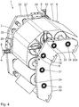
- Fig. 4 a material defect detection device 1 explained in more detail, which in principle according to Fig. 3 equivalent.
- Identical components are given the same reference numerals as the previous embodiment, to which reference is hereby made.
- Structurally different, but functionally similar components receive the same reference numerals with a subordinate "a".
- the frame 23a has two frame parts 29, which are made substantially identical and parallel to each other.
- the deflection rollers 24 to 28 each have an axis 30 to 34 which are rotatably mounted in the frame parts 29 and parallel to each other.
- the first deflection roller 24 is the material web inlet point.
- In the fifth deflection roller 28 is the material web outlet point.
- the web 7 has after the deflection roller 28 a different direction than in front of the deflection roller 24.
- the transmitter 8, 10 are fixed to the one frame part 29, while the receiver 9, 11 are arranged on the other frame part 29.
- the first sensor unit 4 is arranged between the second and third deflection rollers 25 and 26, while the second sensor unit 5 is arranged between the fourth and fifth deflection rollers 27 and 28, respectively.
- the material web 7 extends substantially perpendicular to the material web 7 in the region of the second sensor unit 5. Another orientation is alternatively possible.
- the transmitters 8, 10 are again arranged such that they monitor the upper side 17 of the material web 7.
- the receivers 9, 11 are arranged such that they receive the light sensor beams 12 and 13, which again run parallel to the material web 7 in the region of the respective sensor unit 4, 5.
- the lowermost first and second light sensor beams 12, 13 are directed to the deflection rollers 25, 26 and 27, respectively.
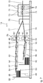
- a corrugated board system described in the at least one material defect detection device 1 according to Fig. 1 to 4 is arranged.
- the material web 7 of the machine 35 is supplied.
- the material web 7 is an endless paper web.
- the material web 7 represents a basic trajectory for the corrugated cardboard produced in the machine 35.
- Fig. 6 shows an enlarged side view of the material web 7.
- This has a material base layer 36 with a print quality enhancing coating 37, a so-called primer on.
- the thickness ratio between the base material layer 36 and the coating 37 is not shown in relation.
- the coating 37 does not necessarily have to be present on the rolled material web 7, but can also be applied to the material web 7 later after the unwinding of the supply roll 21.
- the material web 7 passes through a first digital printing unit 38 with a print head 39 which, in accordance with a print job, prints the upper side 17 of the material web 7.
- the digital printing unit 38 is connected via a signal line 40 with a job control device 41 in connection.
- the printed material web 7 is brought together in the machine 35 with a further or second material web 42, which is unrolled by a second supply roll 43. After unwinding, the second web of material 42 is passed in the machine 35 to create a corrugation between adjacent corrugated rolls 44. The second material web 42 is present after this passage as a corrugated web.
- the tips of the corrugated material web 42 are glued in a gluing device 45 and the corrugated material web 42 is compressed in the machine 35 with the material web 7 in a gap between a pressure roller 46 and one of the corrugating rollers 44 and interconnected.
- a single-faced corrugated cardboard web 47 is removed upward and deflected by a deflection roller 48 in a direction of work 49.
- the corrugated cardboard web 47 is then guided into a preheating device 50.
- the machine 35 is arranged downstream of a third supply roller 51 for a third material web 52 as a further cover web for the corrugated cardboard web 47 in the working direction 49. It is also sometimes customary to designate the third material web 52 as a laminating web, in which case the first material web 7 is referred to as a cover web.
- the third material web 52 is first deflected about a deflection roller 53 in such a way that it is guided in the working direction 49. Subsequently, the third material web 52 is rotated by 180.degree. By two further deflection rollers 54, 55 so that its side pointing downwards between the deflection rollers 53, 54 now points upward, with the third material web 52 after the deflection roller 55 is guided against the working direction 49.
- the third material web 52 passes through a second digital printing unit 56, which together with the first digital printing unit 38 forms a digital printing device.
- the after the deflecting roller 55 upwardly facing side of the third material web 52 is in the second digital printing unit 56 by a printhead 57 according to a Printed job printed.
- the third material web 52 likewise has a two-layer structure with a base material layer and a coating such that the coating of the third material web 52 is printed by means of the print head 57 of the second digital printing unit 56.
- the coating of the third material web 52 can also be applied after unrolling and before the second digital printing unit 56.
- the second digital printing unit 56 is for print job control via a signal line 58 to the job control device 41 in connection.
- the third material web 52 is again deflected by substantially 180 ° with the aid of further deflection rollers 59, 60, so that the third material web 52 is conveyed again essentially in the working direction 49.
- the third material web 52 is fed to the preheating device 50 after the deflection roller 60. This has two superposed, heated heating rollers 61.
- the corrugated cardboard web 47 and the third material web 52 pass over one another and partially wrap around the respective heating rollers 61.
- a gluing unit 62 with a gluing roller 63 is arranged, which partially dips into a glue bath 64.
- the corrugated material web 42 of the corrugated cardboard web 47 is in contact with the gluing roller 63.
- a heating-pressing device 65 is arranged, which has a horizontal, extending in the working direction 49 table 66 with heating plates. Above the table 66 is over three rollers 67 deflected, driven, endless pressure belt 68 is provided.
- a Anpressspalt 69 is formed, through which the corrugated cardboard web 47 and the third web of material 52 are guided and pressed there together.
- a three-ply corrugated board web 70 is formed.
- Fig. 7 shows a second part of the corrugated board plant following the exit of the corrugated cardboard web 70 from the heating-pressing device 65.
- a longitudinal cutting-rill device 71 is arranged, which consists of two successively arranged grooves Stations 72 and two successively arranged longitudinal cutting stations 73 is formed.
- the creasing stations 72 each have pairs of creasing tools 74 arranged one above the other, between which the corrugated cardboard web 70 is passed.
- the longitudinal cutting stations 73 each have rotary drivable knives 75, which can be brought into engagement with the corrugated cardboard web 70 for the longitudinal sectioning thereof.
- a switch 76 is arranged in the longitudinally cut web portions 77, 78 of the corrugated cardboard web 70 are separated from each other.
- the web sections 77, 78 are subsequently fed to a cross-cutting device 79.
- This has an upper transverse cutting roller pair 80 for the upper web section 77 and a lower transverse cutting roller pair 81 for the lower web section 78.
- the rolls of the pairs of rolls 80, 81 each carry a knife bar 82 extending radially outwards and perpendicular to the working direction 49.
- the knife bars 82 of a cross-cut pair of rolls 80, 81 cooperate for the transverse sectioning of the web sections 77, 78.
- the upper cross cutting roller pair 80 is an upper conveyor belt 83 downstream, which is deflected about rotatably driven rollers 84.
- a tray 85 is arranged with vertically extending stop 86, on which from the web section 77 by means of the cross-cutting device 79 cut corrugated sheets 87 stacking a stack 88 are formed.
- the tray 85 is as in Fig. 7 indicated by a directional arrow 89, adjustable in height. In particular, the tray 85 may be lowered for further transport of the stack 88 to a machine floor 90 supporting the corrugator.
- the lower transverse cutting roller pair 81 is followed by a further, lower conveyor belt 91, the corrugated sheets 92, which were cut by means of the cross-cutting device 79 from the web section 78, stacked on another tray 93.
- the lower conveyor belt 91 can be raised, as indicated by a directional arrow 95.
- the material defect detection device 1 is arranged in the corrugated cardboard plant.
- the material defect detection apparatus 1 is disposed between the supply roll 21 and the machine 35.
- this is arranged between the supply roll 21 and the digital printing unit 38.
- the material defect detection device 1 is preferably arranged between the supply roll 51 and the digital printing unit 56.
- the material defect detection device 1 is arranged between the supply roll 51 and the digital printing unit 56.
- the material web monitoring is usefully arranged after this process step, since e.g. can be generated by the moisture input a critical Bruwellung.
- no third material web 52 is used. According to an alternative embodiment, further material webs are used.
Landscapes
- Engineering & Computer Science (AREA)
- General Health & Medical Sciences (AREA)
- Pathology (AREA)
- Health & Medical Sciences (AREA)
- Life Sciences & Earth Sciences (AREA)
- Chemical & Material Sciences (AREA)
- Analytical Chemistry (AREA)
- Physics & Mathematics (AREA)
- General Physics & Mathematics (AREA)
- Biochemistry (AREA)
- Immunology (AREA)
- Textile Engineering (AREA)
- Mechanical Engineering (AREA)
- Controlling Sheets Or Webs (AREA)
- Investigating Materials By The Use Of Optical Means Adapted For Particular Applications (AREA)
- Controlling Rewinding, Feeding, Winding, Or Abnormalities Of Webs (AREA)
Claims (17)
- Installation destinée à traiter une bande de papier ou une bande de carton ondulé,a) avec un premier dispositif de stockage (21) pour l'approvisionnement de la bande de papier ou de la bande de carton ondulé (7) à traiter, etb) avec un dispositif d'impression (38) agencé en aval du premier dispositif de stockage (21) pour imprimer la bande de papier ou la bande de carton ondulé (7),caractérisé parc) un équipement pour détecter des défauts de matériau (20) sur la bande de papier ou la bande de carton ondulé (7) déplacée dans un sens de transport (6), comprenanti) un dispositif de détection (2)- avec une première unité de détection (4)-- avec un premier émetteur (8) pour émettre des premiers rayons de détecteur (12), et-- avec un premier récepteur (9) affecté au premier émetteur (8) pour recevoir les premiers rayons de détecteur (12),-- dans laquelle les premiers rayons de détecteur (12) courent parallèlement au côté de la surface de matériau (17) à surveiller de la bande de papier ou de la bande de carton ondulé (7) pour détecter les défauts de matériau (20) et parcourent un premier trajet de signal S1 entre le premier émetteur (8) et le premier récepteur (9), et- avec au moins une deuxième unité de détection (5)-- avec un deuxième émetteur (10) pour émettre des deuxièmes rayons de détecteur (13), et-- avec un deuxième récepteur (11) affecté au deuxième émetteur (10) pour recevoir les deuxièmes rayons de détecteur (13),-- dans laquelle les deuxièmes rayons de détecteur (13) courent parallèlement au côté de la surface de matériau (17) à surveiller de la bande de papier ou de la bande de carton ondulé (7) pour détecter les défauts de matériau (20) et parcourent un deuxième trajet de signal S2 entre le deuxième émetteur (10) et le deuxième récepteur (11),- dans laquelle la première unité de détection (4) et la deuxième unité de détection (5) sont orientées de telle sorte que la distance mutuelle entre les premiers rayons de détecteur (12) et les deuxièmes rayons de détecteur (13) relativement au sens de transport (6) se modifie sur leur trajet de signal S1, S2, etii) une unité d'analyse de signal (3) qui se situe en liaison de signalisation avec le premier récepteur (9) et le deuxième récepteur (11) pour analyser les défauts de matériau (20) détectés,iii) dans laquelle l'équipement pour détecter des défauts de matériau (20) sur la bande de papier ou la bande de carton ondulé (7) est agencé entre le premier dispositif de stockage (21) et le dispositif d'impression (38) pour détecter sur la bande de papier ou la bande de carton ondulé (7) des défauts de matériau (20) qui posent problème pour l'impression.
- Installation selon la revendication 1, caractérisée en ce que l'unité d'analyse de signal (3) détermine, à l'aide d'une vitesse de la bande de papier ou de la bande de carton ondulé (7) dans le sens de transport (6) et d'une durée qui s'étire entre la détection du défaut de matériau (20) par la première unité de détection (4) et la détection par la au moins deuxième unité de détection (5), l'angle de situation du défaut de matériau (20), la largeur du défaut de matériau (20) et/ou en particulier la position du défaut de matériau (20) par rapport à la bande de papier ou à la bande de carton ondulé (7).
- Installation selon la revendication 1 ou 2, caractérisée en ce que les premiers et/ou deuxièmes rayons de détecteur (12, 13) courent à l'oblique par rapport au sens de transport (6) sur la largeur de la bande de papier ou de la bande de carton ondulé (7).
- Installation selon l'une quelconque des revendications précédentes, caractérisée en ce que le premier émetteur (8) et le deuxième émetteur (10) présentent une distance d'émetteur SA (Senderabstand) mutuelle par rapport au sens de transport (6), dans laquelle le premier récepteur (9) et le deuxième récepteur (11) présentent une distance de récepteur EA (Empfängerabstand) mutuelle par rapport au sens de transport (6), dans laquelle la distance d'émetteur SA et la distance de récepteur EA se différencient l'une de l'autre d'au moins 10 %, de préférence d'au moins 50 %, le plus préférablement d'au moins 100 %.
- Installation selon l'une quelconque des revendications précédentes, caractérisée en ce que les premiers et deuxièmes rayons de détecteur (12, 13) incluent en valeur un angle (Winkel) W1, W2 différent par rapport à une perpendiculaire (19) de la bande de papier ou de la bande de carton ondulé (7) courant perpendiculairement au sens de transport (6).
- Installation selon l'une quelconque des revendications précédentes, caractérisée en ce que le premier émetteur (8) et/ou le deuxième émetteur (10) produisent un rideau de rayons de détecteur avec des premiers et respectivement deuxièmes rayons de détecteur (12, 13) courant parallèlement les uns aux autres, dans laquelle les premiers et respectivement deuxièmes rayons de détecteur (12, 13) présentent des distances perpendiculaires diverses par rapport au côté de la surface de matériau (17) à surveiller de la bande de papier ou de la bande de carton ondulé (7) pour déterminer la hauteur des défauts de matériau (20) détecté.
- Installation selon la revendication 6, caractérisée en ce que le rideau de rayons de détecteur détecte un ou les deux des côtés de la surface de matériau (17, 18) de la bande de papier ou de la bande de carton ondulé (7).
- Installation selon la revendication 6 ou 7, caractérisée en ce que le rideau de rayons de détecteur est formé et agencé de telle sorte qu'il s'étend également sur l'épaisseur de la bande de papier ou de la bande de carton ondulé (7) pour détecter les mêmes.
- Installation selon l'une quelconque des revendications précédentes, caractérisée en ce que l'unité d'analyse de signal (3) convertit la durée détectée, qui s'étire entre la détection du défaut de matériau (20) par la première unité de détection (4) et la détection par la au moins deuxième unité de détection (5), en des trajets de différence pour le calcul de la position du défaut de matériau (20) pendant une accélération ou une décélération de la bande de papier ou de la bande de carton ondulé (7).
- Installation selon l'une quelconque des revendications précédentes, caractérisée en ce qu'en présence d'un défaut de matériau (20) détecté s'effectue un ajustement correspondant des dispositifs de traitement ultérieurs pour éviter une collision avec le défaut de matériau (20) en relief.
- Installation selon l'une quelconque des revendications précédentes, caractérisée en ce que le cas échéant s'effectue un ajustement du dispositif d'impression (38) et/ou de la bande de papier ou de la bande de carton ondulé (7) au moins dans la région du dispositif d'impression (38) pour éviter une collision entre le dispositif d'impression (38) et le défaut de matériau (20) en relief détecté.
- Installation selon l'une quelconque des revendications précédentes, caractérisée en ce que s'effectue une protection du dispositif d'impression (38) par au moins un dispositif de protection face à un défaut de matériau (20) dangereux pour le dispositif d'impression (38).
- Installation selon l'une quelconque des revendications précédentes, caractérisée par un second dispositif de stockage (43) pour l'approvisionnement d'une seconde bande de matériau (42) et un dispositif d'ondulation (44) pour faire onduler la seconde bande de matériau (42), dans laquelle un dispositif de liaison (35) relie ensemble la bande de matériau imprimée (7) et la seconde bande de matériau (42) ondulée.
- Procédé destiné à détecter des défauts de matériau (20) sur une bande de papier ou une bande de carton ondulé (7) déplacée dans un sens de transport (6), comprenant les étapes de- préparation d'un premier dispositif de stockage (21) pour l'approvisionnement de la bande de papier ou de la bande de carton ondulé (7) à traiter,- préparation d'un dispositif d'impression (38) agencé en aval du premier dispositif de stockage (21) pour imprimer la bande de papier ou la bande de carton ondulé (7), et- préparation d'un équipement pour détecter des défauts de matériau (20) sur la bande de papier ou la bande de carton ondulé (7) déplacée dans un sens de transport (6), comprenanta) un dispositif de détection (2)aa) avec une première unité de détection (4)i) avec un premier émetteur (8) pour émettre des premiers rayons de détecteur (12), etii) avec un premier récepteur (9) affecté au premier émetteur (8) pour recevoir les premiers rayons de détecteur (12),iii) dans lequel les premiers rayons de détecteur (12) courent parallèlement au côté de la surface de matériau (17) à surveiller de la bande de papier ou de la bande de carton ondulé (7) pour détecter les défauts de matériau (20) et parcourent un premier trajet de signal S1 entre le premier émetteur (8) et le premier récepteur (9), etab) avec au moins une deuxième unité de détection (5)i) avec un deuxième émetteur (10) pour émettre des deuxièmes rayons de détecteur (13), etii) avec un deuxième récepteur (11) affecté au deuxième émetteur (10) pour recevoir les deuxièmes rayons de détecteur (13),iii) dans lequel les deuxièmes rayons de détecteur (13) courent parallèlement au côté de la surface de matériau (17) à surveiller de la bande de papier ou de la bande de carton ondulé (7) pour détecter les défauts de matériau (20) et parcourent un deuxième trajet de signal S2 entre le deuxième émetteur (10) et le deuxième récepteur (11),ac) dans lequel la première unité de détection (4) et la deuxième unité de détection (5) sont orientées de telle sorte que la distance mutuelle entre les premiers rayons de détecteur (12) et les deuxièmes rayons de détecteur (13) relativement au sens de transport (6) se modifie sur leur trajet de signal S1, S2, etb) une unité d'analyse de signal (3) qui se situe en liaison de signalisation avec le premier récepteur (9) et le deuxième récepteur (11) pour analyser les défauts de matériau (20) détectés,- dans lequel l'équipement pour détecter des défauts de matériau (20) sur la bande de papier ou la bande de carton ondulé (7) est agencé entre le premier dispositif de stockage (21) et le dispositif d'impression (38) pour détecter sur la bande de papier ou la bande de carton ondulé (7) des défauts de matériau (20) qui posent problème pour l'impression.
- Procédé selon la revendication 14, caractérisé en ce que l'unité d'analyse de signal (3) délivre un message de défaut uniquement lorsque le défaut de matériau (20) se situe en dehors de limites de tolérance variablement définissables en matière de hauteur et/ou de position sur la largeur de bande et/ou la longueur.
- Procédé selon la revendication 14 ou 15, caractérisé en ce que l'unité d'analyse de signal (3) délivre un message de défaut lorsque la première unité de détection (4) et/ou la deuxième unité de détection (5) détecte un défaut de matériau (20).
- Procédé selon l'une quelconque des revendications 14 à 16, caractérisé en ce que s'effectue une protection du dispositif d'impression (38) face à un défaut de matériau (20) critique pour le dispositif d'impression (38) lorsqu'un défaut de matériau (20) correspondant est détecté.
Applications Claiming Priority (2)
| Application Number | Priority Date | Filing Date | Title |
|---|---|---|---|
| DE102013202871.7A DE102013202871A1 (de) | 2013-02-21 | 2013-02-21 | Materialfehler-Erfassungs-Vorrichtung |
| PCT/EP2014/053108 WO2014128115A1 (fr) | 2013-02-21 | 2014-02-18 | Installation de traitement d'une bande de papier ou d'une bande de carton ondulé |
Publications (2)
| Publication Number | Publication Date |
|---|---|
| EP2958744A1 EP2958744A1 (fr) | 2015-12-30 |
| EP2958744B1 true EP2958744B1 (fr) | 2017-10-25 |
Family
ID=50114373
Family Applications (1)
| Application Number | Title | Priority Date | Filing Date |
|---|---|---|---|
| EP14704821.9A Not-in-force EP2958744B1 (fr) | 2013-02-21 | 2014-02-18 | Installation et procédé de traitement d'une bande de papier ou d'une bande de carton ondulé |
Country Status (5)
| Country | Link |
|---|---|
| US (1) | US9365382B2 (fr) |
| EP (1) | EP2958744B1 (fr) |
| DE (1) | DE102013202871A1 (fr) |
| ES (1) | ES2649470T3 (fr) |
| WO (1) | WO2014128115A1 (fr) |
Families Citing this family (17)
| Publication number | Priority date | Publication date | Assignee | Title |
|---|---|---|---|---|
| DE102015000191A1 (de) * | 2015-01-03 | 2016-07-21 | RSD - Industrietechnik GmbH | Verklebungs Kontrolle |
| GB2542569B (en) * | 2015-09-22 | 2021-04-28 | Ds Smith Packaging Ltd | A combination of a printed roll and a print roll inventory map |
| DE102015218325A1 (de) | 2015-09-24 | 2017-03-30 | Bhs Corrugated Maschinen- Und Anlagenbau Gmbh | Wellpappe-Anlage |
| DE102015218338A1 (de) | 2015-09-24 | 2017-03-30 | Bhs Corrugated Maschinen- Und Anlagenbau Gmbh | Wellpappeanlage |
| ITUA20161809A1 (it) * | 2016-03-18 | 2017-09-18 | Biomed Srl | Sistema e metodo per il trasporto di beni |
| DE102016206016A1 (de) * | 2016-04-12 | 2017-10-12 | Bhs Corrugated Maschinen- Und Anlagenbau Gmbh | Wellpappeanlage |
| DE102017001946A1 (de) * | 2017-02-28 | 2018-08-30 | RSD - Industrietechnik GmbH | Bahnspannungs-Entkoppelungs-Einrichtung |
| CA3049481C (fr) * | 2017-03-02 | 2022-11-01 | Abzac Canada Inc. | Procede et systeme en ligne, sans contact et non destructifs pour detecter des defauts dans une structure en carton mobile |
| EP3450185B1 (fr) * | 2017-09-01 | 2021-05-05 | Canon Production Printing Holding B.V. | Détection de défauts sur un support d'impression |
| DE102017219064A1 (de) * | 2017-10-25 | 2019-04-25 | Texmag Gmbh Vertriebsgesellschaft | Messsystem für wellpappenmaschine |
| DE102019206779A1 (de) * | 2018-06-13 | 2019-12-19 | Heidelberger Druckmaschinen Ag | Bildinspektionsroboter |
| WO2020222783A1 (fr) * | 2019-04-30 | 2020-11-05 | Hewlett-Packard Development Company, L.P. | Détection de non-uniformité de hauteur de support |
| EP3828241A1 (fr) | 2019-11-29 | 2021-06-02 | TIGER Coatings GmbH & Co. KG | Concentré de pigment aqueux, encre aqueuse pour jet d'encre et son utilisation |
| EP3828242A1 (fr) | 2019-11-29 | 2021-06-02 | TIGER Coatings GmbH & Co. KG | Encre aqueuse pour jet d'encre et son utilisation |
| EP4309908A1 (fr) | 2022-07-21 | 2024-01-24 | TIGER Coatings GmbH & Co. KG | Procédé et ensemble de recouvrement d'un substrat imprimé |
| CN116908099A (zh) * | 2023-07-06 | 2023-10-20 | 南亚新材料科技(江西)有限公司 | 一种覆铜板行业上胶机断布在线监测装置及监测方法 |
| WO2026017613A1 (fr) | 2024-07-15 | 2026-01-22 | Agfa Nv | Procédé d'impression d'image |
Family Cites Families (9)
| Publication number | Priority date | Publication date | Assignee | Title |
|---|---|---|---|---|
| CA951398A (en) | 1970-02-13 | 1974-07-16 | Louis B. Williams (Jr.) | Device for locating and identifying threadline defects |
| DE10161502A1 (de) * | 2001-12-14 | 2003-06-26 | Arteva Tech Sarl | Verfahren und Vorrichtung zur kontinuierlichen Ermittlung und Lokalisierung von Fadenfehlern einer in einer Ebene laufenden Fadenschar |
| US7114444B2 (en) * | 2003-06-30 | 2006-10-03 | Compak, Inc. | Apparatus and method for providing registered printing on separate continuous webs of paperboard material for forming into multiple box blanks |
| US20060148631A1 (en) | 2004-12-30 | 2006-07-06 | Corrugated Supplies Corporation | Manufacturing line for making corrugated cardboard |
| KR100899114B1 (ko) * | 2006-05-23 | 2009-05-26 | 주식회사 케이씨텍 | 이물질 감지 장치 및 방법 |
| JP2008246879A (ja) * | 2007-03-30 | 2008-10-16 | Brother Ind Ltd | 画像記録装置 |
| US8419144B2 (en) * | 2010-05-11 | 2013-04-16 | Xerox Corporation | Media handling device for a printer |
| US9676202B2 (en) * | 2012-05-09 | 2017-06-13 | Xerox Corporation | System and method for detecting defects in an inkjet printer |
| JP6135139B2 (ja) * | 2013-01-17 | 2017-05-31 | セイコーエプソン株式会社 | 液体吐出装置 |
-
2013
- 2013-02-21 DE DE102013202871.7A patent/DE102013202871A1/de not_active Ceased
-
2014
- 2014-02-18 EP EP14704821.9A patent/EP2958744B1/fr not_active Not-in-force
- 2014-02-18 US US14/768,546 patent/US9365382B2/en not_active Expired - Fee Related
- 2014-02-18 ES ES14704821.9T patent/ES2649470T3/es active Active
- 2014-02-18 WO PCT/EP2014/053108 patent/WO2014128115A1/fr not_active Ceased
Non-Patent Citations (1)
| Title |
|---|
| None * |
Also Published As
| Publication number | Publication date |
|---|---|
| EP2958744A1 (fr) | 2015-12-30 |
| ES2649470T3 (es) | 2018-01-12 |
| DE102013202871A1 (de) | 2014-09-04 |
| US20160009516A1 (en) | 2016-01-14 |
| US9365382B2 (en) | 2016-06-14 |
| WO2014128115A1 (fr) | 2014-08-28 |
Similar Documents
| Publication | Publication Date | Title |
|---|---|---|
| EP2958744B1 (fr) | Installation et procédé de traitement d'une bande de papier ou d'une bande de carton ondulé | |
| EP1459878B1 (fr) | Machine de fabrication de carton ondulé et fabrication des feuilles en carton ondulé | |
| DE10312601A1 (de) | Material-Bahn sowie Verfahren zur Herstellung von Wellpappe | |
| EP3277494B1 (fr) | Dispositif de détermination de la qualité d'une bande de carton ondulé | |
| EP3064327B1 (fr) | Procede de correction de registre d'une presse de decoupe a plat | |
| EP2048494B1 (fr) | Dispositif destiné à la détermination du format précis d'une bande de carton ondulé | |
| EP3354426A1 (fr) | Correction de position pour les marques de repérage en coupant carton ondulé | |
| EP1731297B1 (fr) | Machine de carton ondulé | |
| EP3283285A1 (fr) | Installation de fabrication d'une bande de carton ondulé | |
| DE10237544A1 (de) | Verpackung, Zuschnitt für dieselbe und Verfahren zu deren Herstellung | |
| EP3867178B1 (fr) | Machine traitant un substrat en forme de plaque comprenant une installation, procédé d'agencement et procédé de fonctionnement d'une installation | |
| DE10101860C1 (de) | Verfahren zur Bearbeitung einer Materialbahn | |
| DE102009047776B4 (de) | Verfahren und Vorrichtung zum Messen einer Laufrichtung einer Substratbahn | |
| EP3077306B1 (fr) | Dispositif et procédé de découpage d'un matériau en bande en bandes partielles et d'écartement des bandes partielles | |
| DE202013105426U1 (de) | Spleißvorrichtung zum Überlappspleißen von Cordbandstreifen | |
| DE4235452A1 (de) | Verarbeitungsvorrichtung für Blattlagen sowie Verfahren zur Bearbeitung von Blattlagen | |
| EP0534080B1 (fr) | Bande de formulaires controlée continuellement, dispositif et méthode pour sa fabrication | |
| EP3875262A2 (fr) | Installation de fabrication de boîtes pliables et procédés de fonctionnement de l'installation | |
| DE3744107A1 (de) | Einrichtung zur herstellung von querlinien an materialbahnen | |
| EP4626693A1 (fr) | Onduleuse | |
| WO2026032839A1 (fr) | Ensemble de coupe | |
| WO2025237979A1 (fr) | Agencement pour influencer des feuilles et procédé pour influencer des feuilles transportées | |
| DE102014215811A1 (de) | Wellpappe-Herstell-Anordnung |
Legal Events
| Date | Code | Title | Description |
|---|---|---|---|
| PUAI | Public reference made under article 153(3) epc to a published international application that has entered the european phase |
Free format text: ORIGINAL CODE: 0009012 |
|
| 17P | Request for examination filed |
Effective date: 20150821 |
|
| AK | Designated contracting states |
Kind code of ref document: A1 Designated state(s): AL AT BE BG CH CY CZ DE DK EE ES FI FR GB GR HR HU IE IS IT LI LT LU LV MC MK MT NL NO PL PT RO RS SE SI SK SM TR |
|
| AX | Request for extension of the european patent |
Extension state: BA ME |
|
| DAX | Request for extension of the european patent (deleted) | ||
| GRAP | Despatch of communication of intention to grant a patent |
Free format text: ORIGINAL CODE: EPIDOSNIGR1 |
|
| STAA | Information on the status of an ep patent application or granted ep patent |
Free format text: STATUS: GRANT OF PATENT IS INTENDED |
|
| INTG | Intention to grant announced |
Effective date: 20170530 |
|
| GRAS | Grant fee paid |
Free format text: ORIGINAL CODE: EPIDOSNIGR3 |
|
| GRAA | (expected) grant |
Free format text: ORIGINAL CODE: 0009210 |
|
| STAA | Information on the status of an ep patent application or granted ep patent |
Free format text: STATUS: THE PATENT HAS BEEN GRANTED |
|
| AK | Designated contracting states |
Kind code of ref document: B1 Designated state(s): AL AT BE BG CH CY CZ DE DK EE ES FI FR GB GR HR HU IE IS IT LI LT LU LV MC MK MT NL NO PL PT RO RS SE SI SK SM TR |
|
| REG | Reference to a national code |
Ref country code: GB Ref legal event code: FG4D Free format text: NOT ENGLISH |
|
| REG | Reference to a national code |
Ref country code: CH Ref legal event code: EP |
|
| REG | Reference to a national code |
Ref country code: AT Ref legal event code: REF Ref document number: 939525 Country of ref document: AT Kind code of ref document: T Effective date: 20171115 |
|
| REG | Reference to a national code |
Ref country code: IE Ref legal event code: FG4D Free format text: LANGUAGE OF EP DOCUMENT: GERMAN |
|
| REG | Reference to a national code |
Ref country code: DE Ref legal event code: R096 Ref document number: 502014005957 Country of ref document: DE |
|
| REG | Reference to a national code |
Ref country code: ES Ref legal event code: FG2A Ref document number: 2649470 Country of ref document: ES Kind code of ref document: T3 Effective date: 20180112 |
|
| REG | Reference to a national code |
Ref country code: FR Ref legal event code: PLFP Year of fee payment: 5 |
|
| REG | Reference to a national code |
Ref country code: NL Ref legal event code: MP Effective date: 20171025 |
|
| REG | Reference to a national code |
Ref country code: LT Ref legal event code: MG4D |
|
| PG25 | Lapsed in a contracting state [announced via postgrant information from national office to epo] |
Ref country code: NL Free format text: LAPSE BECAUSE OF FAILURE TO SUBMIT A TRANSLATION OF THE DESCRIPTION OR TO PAY THE FEE WITHIN THE PRESCRIBED TIME-LIMIT Effective date: 20171025 |
|
| PG25 | Lapsed in a contracting state [announced via postgrant information from national office to epo] |
Ref country code: NO Free format text: LAPSE BECAUSE OF FAILURE TO SUBMIT A TRANSLATION OF THE DESCRIPTION OR TO PAY THE FEE WITHIN THE PRESCRIBED TIME-LIMIT Effective date: 20180125 Ref country code: LT Free format text: LAPSE BECAUSE OF FAILURE TO SUBMIT A TRANSLATION OF THE DESCRIPTION OR TO PAY THE FEE WITHIN THE PRESCRIBED TIME-LIMIT Effective date: 20171025 Ref country code: FI Free format text: LAPSE BECAUSE OF FAILURE TO SUBMIT A TRANSLATION OF THE DESCRIPTION OR TO PAY THE FEE WITHIN THE PRESCRIBED TIME-LIMIT Effective date: 20171025 Ref country code: SE Free format text: LAPSE BECAUSE OF FAILURE TO SUBMIT A TRANSLATION OF THE DESCRIPTION OR TO PAY THE FEE WITHIN THE PRESCRIBED TIME-LIMIT Effective date: 20171025 |
|
| PG25 | Lapsed in a contracting state [announced via postgrant information from national office to epo] |
Ref country code: RS Free format text: LAPSE BECAUSE OF FAILURE TO SUBMIT A TRANSLATION OF THE DESCRIPTION OR TO PAY THE FEE WITHIN THE PRESCRIBED TIME-LIMIT Effective date: 20171025 Ref country code: GR Free format text: LAPSE BECAUSE OF FAILURE TO SUBMIT A TRANSLATION OF THE DESCRIPTION OR TO PAY THE FEE WITHIN THE PRESCRIBED TIME-LIMIT Effective date: 20180126 Ref country code: HR Free format text: LAPSE BECAUSE OF FAILURE TO SUBMIT A TRANSLATION OF THE DESCRIPTION OR TO PAY THE FEE WITHIN THE PRESCRIBED TIME-LIMIT Effective date: 20171025 Ref country code: IS Free format text: LAPSE BECAUSE OF FAILURE TO SUBMIT A TRANSLATION OF THE DESCRIPTION OR TO PAY THE FEE WITHIN THE PRESCRIBED TIME-LIMIT Effective date: 20180225 Ref country code: LV Free format text: LAPSE BECAUSE OF FAILURE TO SUBMIT A TRANSLATION OF THE DESCRIPTION OR TO PAY THE FEE WITHIN THE PRESCRIBED TIME-LIMIT Effective date: 20171025 Ref country code: BG Free format text: LAPSE BECAUSE OF FAILURE TO SUBMIT A TRANSLATION OF THE DESCRIPTION OR TO PAY THE FEE WITHIN THE PRESCRIBED TIME-LIMIT Effective date: 20180125 |
|
| REG | Reference to a national code |
Ref country code: DE Ref legal event code: R097 Ref document number: 502014005957 Country of ref document: DE |
|
| PG25 | Lapsed in a contracting state [announced via postgrant information from national office to epo] |
Ref country code: DK Free format text: LAPSE BECAUSE OF FAILURE TO SUBMIT A TRANSLATION OF THE DESCRIPTION OR TO PAY THE FEE WITHIN THE PRESCRIBED TIME-LIMIT Effective date: 20171025 Ref country code: SK Free format text: LAPSE BECAUSE OF FAILURE TO SUBMIT A TRANSLATION OF THE DESCRIPTION OR TO PAY THE FEE WITHIN THE PRESCRIBED TIME-LIMIT Effective date: 20171025 Ref country code: CZ Free format text: LAPSE BECAUSE OF FAILURE TO SUBMIT A TRANSLATION OF THE DESCRIPTION OR TO PAY THE FEE WITHIN THE PRESCRIBED TIME-LIMIT Effective date: 20171025 Ref country code: CY Free format text: LAPSE BECAUSE OF FAILURE TO SUBMIT A TRANSLATION OF THE DESCRIPTION OR TO PAY THE FEE WITHIN THE PRESCRIBED TIME-LIMIT Effective date: 20171025 Ref country code: EE Free format text: LAPSE BECAUSE OF FAILURE TO SUBMIT A TRANSLATION OF THE DESCRIPTION OR TO PAY THE FEE WITHIN THE PRESCRIBED TIME-LIMIT Effective date: 20171025 |
|
| PG25 | Lapsed in a contracting state [announced via postgrant information from national office to epo] |
Ref country code: PL Free format text: LAPSE BECAUSE OF FAILURE TO SUBMIT A TRANSLATION OF THE DESCRIPTION OR TO PAY THE FEE WITHIN THE PRESCRIBED TIME-LIMIT Effective date: 20171025 Ref country code: RO Free format text: LAPSE BECAUSE OF FAILURE TO SUBMIT A TRANSLATION OF THE DESCRIPTION OR TO PAY THE FEE WITHIN THE PRESCRIBED TIME-LIMIT Effective date: 20171025 Ref country code: SM Free format text: LAPSE BECAUSE OF FAILURE TO SUBMIT A TRANSLATION OF THE DESCRIPTION OR TO PAY THE FEE WITHIN THE PRESCRIBED TIME-LIMIT Effective date: 20171025 |
|
| PLBE | No opposition filed within time limit |
Free format text: ORIGINAL CODE: 0009261 |
|
| STAA | Information on the status of an ep patent application or granted ep patent |
Free format text: STATUS: NO OPPOSITION FILED WITHIN TIME LIMIT |
|
| REG | Reference to a national code |
Ref country code: CH Ref legal event code: PL |
|
| PG25 | Lapsed in a contracting state [announced via postgrant information from national office to epo] |
Ref country code: MC Free format text: LAPSE BECAUSE OF FAILURE TO SUBMIT A TRANSLATION OF THE DESCRIPTION OR TO PAY THE FEE WITHIN THE PRESCRIBED TIME-LIMIT Effective date: 20171025 Ref country code: MT Free format text: LAPSE BECAUSE OF FAILURE TO SUBMIT A TRANSLATION OF THE DESCRIPTION OR TO PAY THE FEE WITHIN THE PRESCRIBED TIME-LIMIT Effective date: 20171025 |
|
| 26N | No opposition filed |
Effective date: 20180726 |
|
| REG | Reference to a national code |
Ref country code: IE Ref legal event code: MM4A |
|
| REG | Reference to a national code |
Ref country code: BE Ref legal event code: MM Effective date: 20180228 |
|
| PG25 | Lapsed in a contracting state [announced via postgrant information from national office to epo] |
Ref country code: LU Free format text: LAPSE BECAUSE OF NON-PAYMENT OF DUE FEES Effective date: 20180218 Ref country code: SI Free format text: LAPSE BECAUSE OF FAILURE TO SUBMIT A TRANSLATION OF THE DESCRIPTION OR TO PAY THE FEE WITHIN THE PRESCRIBED TIME-LIMIT Effective date: 20171025 Ref country code: CH Free format text: LAPSE BECAUSE OF NON-PAYMENT OF DUE FEES Effective date: 20180228 Ref country code: LI Free format text: LAPSE BECAUSE OF NON-PAYMENT OF DUE FEES Effective date: 20180228 |
|
| PG25 | Lapsed in a contracting state [announced via postgrant information from national office to epo] |
Ref country code: IE Free format text: LAPSE BECAUSE OF NON-PAYMENT OF DUE FEES Effective date: 20180218 |
|
| PG25 | Lapsed in a contracting state [announced via postgrant information from national office to epo] |
Ref country code: BE Free format text: LAPSE BECAUSE OF NON-PAYMENT OF DUE FEES Effective date: 20180228 |
|
| PG25 | Lapsed in a contracting state [announced via postgrant information from national office to epo] |
Ref country code: TR Free format text: LAPSE BECAUSE OF FAILURE TO SUBMIT A TRANSLATION OF THE DESCRIPTION OR TO PAY THE FEE WITHIN THE PRESCRIBED TIME-LIMIT Effective date: 20171025 |
|
| REG | Reference to a national code |
Ref country code: AT Ref legal event code: MM01 Ref document number: 939525 Country of ref document: AT Kind code of ref document: T Effective date: 20190218 |
|
| PG25 | Lapsed in a contracting state [announced via postgrant information from national office to epo] |
Ref country code: AT Free format text: LAPSE BECAUSE OF NON-PAYMENT OF DUE FEES Effective date: 20190218 |
|
| PGFP | Annual fee paid to national office [announced via postgrant information from national office to epo] |
Ref country code: GB Payment date: 20200225 Year of fee payment: 7 Ref country code: ES Payment date: 20200320 Year of fee payment: 7 Ref country code: IT Payment date: 20200221 Year of fee payment: 7 |
|
| PG25 | Lapsed in a contracting state [announced via postgrant information from national office to epo] |
Ref country code: PT Free format text: LAPSE BECAUSE OF FAILURE TO SUBMIT A TRANSLATION OF THE DESCRIPTION OR TO PAY THE FEE WITHIN THE PRESCRIBED TIME-LIMIT Effective date: 20171025 |
|
| PG25 | Lapsed in a contracting state [announced via postgrant information from national office to epo] |
Ref country code: HU Free format text: LAPSE BECAUSE OF FAILURE TO SUBMIT A TRANSLATION OF THE DESCRIPTION OR TO PAY THE FEE WITHIN THE PRESCRIBED TIME-LIMIT; INVALID AB INITIO Effective date: 20140218 Ref country code: MK Free format text: LAPSE BECAUSE OF NON-PAYMENT OF DUE FEES Effective date: 20171025 |
|
| PGFP | Annual fee paid to national office [announced via postgrant information from national office to epo] |
Ref country code: FR Payment date: 20200220 Year of fee payment: 7 |
|
| PG25 | Lapsed in a contracting state [announced via postgrant information from national office to epo] |
Ref country code: AL Free format text: LAPSE BECAUSE OF FAILURE TO SUBMIT A TRANSLATION OF THE DESCRIPTION OR TO PAY THE FEE WITHIN THE PRESCRIBED TIME-LIMIT Effective date: 20171025 |
|
| PGFP | Annual fee paid to national office [announced via postgrant information from national office to epo] |
Ref country code: DE Payment date: 20200427 Year of fee payment: 7 |
|
| REG | Reference to a national code |
Ref country code: DE Ref legal event code: R119 Ref document number: 502014005957 Country of ref document: DE |
|
| GBPC | Gb: european patent ceased through non-payment of renewal fee |
Effective date: 20210218 |
|
| PG25 | Lapsed in a contracting state [announced via postgrant information from national office to epo] |
Ref country code: FR Free format text: LAPSE BECAUSE OF NON-PAYMENT OF DUE FEES Effective date: 20210228 Ref country code: GB Free format text: LAPSE BECAUSE OF NON-PAYMENT OF DUE FEES Effective date: 20210218 Ref country code: DE Free format text: LAPSE BECAUSE OF NON-PAYMENT OF DUE FEES Effective date: 20210901 |
|
| PG25 | Lapsed in a contracting state [announced via postgrant information from national office to epo] |
Ref country code: IT Free format text: LAPSE BECAUSE OF NON-PAYMENT OF DUE FEES Effective date: 20210218 |
|
| REG | Reference to a national code |
Ref country code: ES Ref legal event code: FD2A Effective date: 20220511 |
|
| PG25 | Lapsed in a contracting state [announced via postgrant information from national office to epo] |
Ref country code: ES Free format text: LAPSE BECAUSE OF NON-PAYMENT OF DUE FEES Effective date: 20210219 |