EP2959059B1 - Maschine zur gleisschotter-reinigung mit gleitendem böschungsverbau - Google Patents
Maschine zur gleisschotter-reinigung mit gleitendem böschungsverbau Download PDFInfo
- Publication number
- EP2959059B1 EP2959059B1 EP14704520.7A EP14704520A EP2959059B1 EP 2959059 B1 EP2959059 B1 EP 2959059B1 EP 14704520 A EP14704520 A EP 14704520A EP 2959059 B1 EP2959059 B1 EP 2959059B1
- Authority
- EP
- European Patent Office
- Prior art keywords
- ballast
- machine
- track
- retaining wall
- pick
- Prior art date
- Legal status (The legal status is an assumption and is not a legal conclusion. Google has not performed a legal analysis and makes no representation as to the accuracy of the status listed.)
- Active
Links
Images
Classifications
-
- E—FIXED CONSTRUCTIONS
- E01—CONSTRUCTION OF ROADS, RAILWAYS, OR BRIDGES
- E01B—PERMANENT WAY; PERMANENT-WAY TOOLS; MACHINES FOR MAKING RAILWAYS OF ALL KINDS
- E01B27/00—Placing, renewing, working, cleaning, or taking-up the ballast, with or without concurrent work on the track; Devices therefor; Packing sleepers
- E01B27/06—Renewing or cleaning the ballast in situ, with or without concurrent work on the track
- E01B27/10—Renewing or cleaning the ballast in situ, with or without concurrent work on the track without taking-up track
Definitions
- the invention relates to a machine for cleaning ballast of a ballast bed of a track, with a movable on rail bogies machine frame, a gravel receiving device for receiving located below the track ballast, a screening, a ballast discharge point for introducing the cleaned ballast into a ballast bed gap formed by the ballast excavation Restoration of ballast bedding, as well as with a track lifting device for lifting the track.
- DE 43 41 418 A discloses a stepwise advancing trench sidewall guard in the form of a sliding knife assembly for refurbishing a track substructure.
- a front and a nachumbleer workspace is formed.
- Tools for a gravel excavation can be arranged in the front working area.
- Such a machine is structurally very expensive and is only suitable in the event that between adjacent tracks a high level difference.
- the object of the present invention is now to provide a machine of the type mentioned, with a problem-free gravel excavation is possible in the case of a neighboring track.
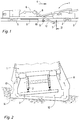
- Fig. 1 a side view of a machine for cleaning ballast of a track
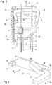
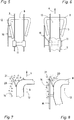
- Fig. 2 to 8 each detail views.
- An in Fig. 1 illustrated machine 1 is movable by rail carriages 2 on a track 3 in a working direction 4.
- a conveyor belt 9 with a ballast discharge point 10 is provided.
- a track lifting device 11 for lifting the track 3 in the area of a ballast bed gap 12 formed by the gravel excavation.
- Fig. 2 is a simplified cross section through the machine 1 according to the section line II in Fig. 1 shown. It is very clear here a transition region 13 of the ballast bed gap 12 formed by the gravel excavation to a ballast bed 14 of an adjacent, not shown adjacent track.
- FIG. 4 According to Fig. 3 and the schematic representation in FIG Fig. 4 is in the transition region of the ballast bed gap 12 to - seen with respect to a cross-machine direction 15 - adjacent ballast bed 14 of a neighboring track running in the machine longitudinal direction, positioned between the ballast picking device 8 and the ballast discharge point 10 support wall 16.
- This vertical plane forming support wall 16 is connected to a front end 17 with the ballast receiving device 8 and in the region of a rear end 18 with the track lifting device 11.
- the support wall thus covers the entire extending in the machine longitudinal length of the ballast bed gap 12 and thus supports the adjacent, exposed ballast bed 14.
- the compounds of the support wall 16 with the machine 1 should be conveniently easy to solve around the support wall 16 in the event that no adjacent adjacent track is available to be able to remove quickly and easily.
- the supporting wall 16 can also be connected in its entirety with the ballast receiving device 8 or with the track lifting device 11 or in a further variant directly with the machine frame 5.
- the ballast receiving device 8 is connected to a baffle 20 and the support wall 16 forms an extension of a front end 21 of the baffle 20th
Landscapes
- Engineering & Computer Science (AREA)
- Architecture (AREA)
- Civil Engineering (AREA)
- Structural Engineering (AREA)
- Machines For Laying And Maintaining Railways (AREA)
- Underground Or Underwater Handling Of Building Materials (AREA)
Description
- Die Erfindung betrifft eine Maschine zur Reinigung von Schotter einer Schotterbettung eines Gleises, mit einem auf Schienenfahrwerken verfahrbaren Maschinenrahmen, einer Schotteraufnahmevorrichtung zur Aufnahme von unterhalb des Gleises gelegenem Schotter, einer Siebanlage, einer Schotterabwurfstelle zur Einbringung des gereinigten Schotters in eine durch den Schotteraushub gebildete Schotterbettlücke zur Wiederherstellung der Schotterbettung, sowie mit einer Gleishebevorrichtung zum Anheben des Gleises.
- Durch
DE 43 17 553 C2 ist ein auf einem Raupenfahrwerk verfahrbarer Bagger bekannt, der seitlich mit einer Abstützwand verbunden ist. Ein vorderer Abschnitt der Abstützwand wird mit Hilfe eines Hydraulikzylinders in das noch auszuhebende Material gepresst. - Außerdem ist durch
DE 195 23 679 C1 eine gleisverfahrbare Maschine zum Aushub der unter einem Gleis befindlichen Schotterbettung bekannt. Eine die Bettungslücke beidseitig begrenzende Schalungseinheit ist mit ihrem vorderen Ende mit rotierbaren Walzen für die Materialübergabe auf Förderbänder verbunden. Die gesamte Schalungseinheit wird durch am hinteren Ende vorgesehene Hydraulikstempel nach vorne gepresst. - Durch
DE 43 12 585 A1 ist eine Schotterbettreinigungsmaschine mit den eingangs genannten Merkmalen bekannt. -
DE 43 41 418 A offenbart eine sich schrittweise vorwärtsbewegende Graben-Seitenwandsicherung in Form eines gleitenden Messerverbaus zur Sanierung eines Gleisunterbaus. Durch voneinander distanzierte Seitenmesser wird ein frontseitiger und ein nachgeführter Arbeitsraum gebildet. Im frontseitigen Arbeitsraum können Werkzeuge für einen Schotteraushub angeordnet sein. Eine derartige Maschine ist konstruktiv sehr aufwendig und eignet sich nur für den Fall, dass zwischen Nachbargleisen eine hoher Niveauunterschied besteht. - Die Aufgabe der vorliegenden Erfindung liegt nun in der Schaffung einer Maschine der eingangs genannten Art, mit der auch im Falle eines Nachbargleises ein problemloser Schotteraushub möglich ist.
- Diese Aufgabe wird erfindungsgemäß mit einer Maschine der gattungsgemäßen Art durch die im Kennzeichen des Hauptanspruches angeführten Merkmale gelöst.
- Mit einer derartigen konstruktiv einfachen Maßnahme kann eine zuverlässige Absicherung des an die Schotterbettlücke angrenzenden Bettungsabschnittes des Nachbargleises erzielt werden, ohne dass die Aushubarbeiten beeinträchtigt werden.
- Weitere Vorteile der Erfindung ergeben sich aus den Unteransprüchen und der Zeichnungsbeschreibung.
- Im Folgenden wird die Erfindung anhand eines in der Zeichnung dargestellten Ausführungsbeispieles näher beschrieben. Es zeigen:
Fig. 1 eine Seitenansicht einer Maschine zur Reinigung von Schotter eines Gleises undFig. 2 bis 8 jeweils Detailansichten. - Eine in
Fig. 1 dargestellte Maschine 1 ist durch Schienenfahrwerke 2 auf einem Gleis 3 in einer Arbeitsrichtung 4 verfahrbar. Auf einem Maschinenrahmen 5 befindet sich eine Siebanlage 6 zur Reinigung von Schotter 7, der unterhalb des Gleises 3 durch eine Schotteraufnahmevorrichtung 8 aufgenommen wird. Zur Rückführung des gereinigten Schotters 7 ist ein Förderband 9 mit einer Schotterabwurfstelle 10 vorgesehen. Unmittelbar vor dieser befindet sich eine Gleishebevorrichtung 11 zum Anheben des Gleises 3 im Bereich einer durch den Schotteraushub gebildeten Schotterbettlücke 12. - In
Fig. 2 ist ein vereinfachter Querschnitt durch die Maschine 1 gemäß der Schnittlinie II inFig. 1 dargestellt. Es ist hier sehr deutlich ein Übergangsbereich 13 von der durch den Schotteraushub gebildeten Schotterbettlücke 12 zu einer Schotterbettung 14 eines angrenzenden, nicht näher dargestellten Nachbargleises ersichtlich. - Gemäß
Fig. 3 und der schematischen Darstellung inFig. 4 ist im Übergangsbereich der Schotterbettlücke 12 zu der - bezüglich einer Maschinenquerrichtung 15 gesehen - angrenzenden Schotterbettung 14 eines Nachbargleises eine in Maschinenlängsrichtung verlaufende, zwischen der Schotteraufnahmevorrichtung 8 und der Schotterabwurfstelle 10 positionierte Stützwand 16 angeordnet. - Diese eine vertikale Ebene bildende Stützwand 16 ist mit einem vorderen Ende 17 mit der Schotteraufnahmevorrichtung 8 und im Bereich eines hinteren Endes 18 mit der Gleishebevorrichtung 11 verbunden. Die Stützwand deckt somit die gesamte in Maschinenlängsrichtung verlaufende Länge der Schotterbettlücke 12 ab und stützt somit die angrenzende, freigelegte Schotterbettung 14. Die Verbindungen der Stützwand 16 mit der Maschine 1 sollten zweckmäßigerweise einfach zu lösen sein, um die Stützwand 16 für den Fall, dass kein angrenzendes Nachbargleis vorhanden ist, rasch und problemlos entfernen zu können.
- Wie in
Fig. 4 ersichtlich, ist zwischen Stützwand 16 und der Schotteraufnahmevorrichtung 8 sowie der Gleishebevorrichtung 11 jeweils ein in Maschinenquerrichtung 15 verlängerbarer hydraulischer Abstützzylinder 19 vorgesehen. Damit kann mit der Stützwand 16 ein wählbarer Druck gegen die angrenzende Schotterbettung 14 ausgeübt werden. - Wie in
Fig. 5 und 6 dargestellt, kann die Stützwand 16 wahlweise auch zur Gänze mit der Schotteraufnahmevorrichtung 8 oder mit der Gleishebevorrichtung 11 bzw. in einer weiteren Variante direkt mit dem Maschinenrahmen 5 verbunden sein. - In
Fig. 7 und 8 ist die Schotteraufnahmevorrichtung 8 mit einem Leitblech 20 verbunden und die Stützwand 16 bildet eine Verlängerung eines vorderen Endes 21 des Leitblechs 20.
Claims (5)
- Maschine zur Reinigung von Schotter (7) einer Schotterbettung eines Gleises (3), mit einem auf Schienenfahrwerken (2) verfahrbaren Maschinenrahmen (5), einer Schotteraufnahmevorrichtung (8) zur Aufnahme von unterhalb des Gleises gelegenem Schotter, einer Siebanlage (6), einer Schotterabwurfstelle (10) zur Einbringung des gereinigten Schotters (7) in eine durch den Schotteraushub gebildete Schotterbettlücke (12) zur Wiederherstellung der Schotterbettung, sowie mit einer Gleishebevorrichtung (11) zum Anheben des Gleises (3), dadurch gekennzeichnet, dass im Übergangsbereich (13) der Schotterbettlücke (12) zu einer bezüglich der Maschinenquerrichtung (15) gesehen angrenzenden Schotterbettung eines Nachbargleises eine in Maschinenlängsrichtung verlaufende, zwischen der Schotteraufnahmevorrichtung (8) und der Schotterabwurfstelle (10) positionierte und mit der Maschine (1) verbundene Stützwand (16) angeordnet ist.
- Maschine nach Anspruch 1, dadurch gekennzeichnet, dass die Stützwand (16) mit einem vorderen Ende (17) an der Schotteraufnahmevorrichtung (8) und mit einem hinteren Ende (18) an der Gleishebevorrichtung (11) befestigt ist.
- Maschine nach Anspruch 2, dadurch gekennzeichnet, dass zwischen Stützwand (16) und der Schotteraufnahmevorrichtung (8) sowie der Gleishebevorrichtung (11) jeweils ein in Maschinenquerrichtung (15) verlängerbarer hydraulischer Abstützzylinder (19) vorgesehen ist.
- Maschine nach Anspruch 1, dadurch gekennzeichnet, dass die Stützwand (16) an der Schotteraufnahmevorrichtung (8) befestigt ist.
- Maschine nach Anspruch 1, dadurch gekennzeichnet, dass die Stützwand (16) an der Gleishebevorrichtung (11) befestigt ist.
Priority Applications (1)
| Application Number | Priority Date | Filing Date | Title |
|---|---|---|---|
| PL14704520T PL2959059T3 (pl) | 2013-02-25 | 2014-01-31 | Maszyna do oczyszczania tłucznia torowiska ze zmienną zabudową zbocza |
Applications Claiming Priority (2)
| Application Number | Priority Date | Filing Date | Title |
|---|---|---|---|
| ATA139/2013A AT513824B1 (de) | 2013-02-25 | 2013-02-25 | Maschine zur Reinigung von Schotter eines Gleises |
| PCT/EP2014/000260 WO2014127883A1 (de) | 2013-02-25 | 2014-01-31 | Maschine zur gleisschotter-reinigung mit gleitendem böschungsverbau |
Publications (2)
| Publication Number | Publication Date |
|---|---|
| EP2959059A1 EP2959059A1 (de) | 2015-12-30 |
| EP2959059B1 true EP2959059B1 (de) | 2017-10-25 |
Family
ID=50112869
Family Applications (1)
| Application Number | Title | Priority Date | Filing Date |
|---|---|---|---|
| EP14704520.7A Active EP2959059B1 (de) | 2013-02-25 | 2014-01-31 | Maschine zur gleisschotter-reinigung mit gleitendem böschungsverbau |
Country Status (8)
| Country | Link |
|---|---|
| EP (1) | EP2959059B1 (de) |
| CN (1) | CN105074088B (de) |
| AT (1) | AT513824B1 (de) |
| EA (1) | EA029067B1 (de) |
| ES (1) | ES2651764T3 (de) |
| NO (1) | NO2959059T3 (de) |
| PL (1) | PL2959059T3 (de) |
| WO (1) | WO2014127883A1 (de) |
Families Citing this family (4)
| Publication number | Priority date | Publication date | Assignee | Title |
|---|---|---|---|---|
| AT518225B1 (de) * | 2016-01-29 | 2017-11-15 | Plasser & Theurer Export Von Bahnbaumaschinen Gmbh | Maschine mit einer Schotteraufnahmevorrichtung |
| CN107090838A (zh) * | 2017-06-21 | 2017-08-25 | 贵州省水利水电勘测设计研究院 | 一种堆积体大方量削坡反压的施工结构及方法 |
| AT520194B1 (de) * | 2017-12-07 | 2019-02-15 | Plasser & Theurer Export Von Bahnbaumaschinen Gmbh | Anlage und Verfahren zur Reinigung von Schotter eines Gleises |
| CN113403895B (zh) * | 2021-06-04 | 2022-03-01 | 中南大学 | 铁路道砟清理平铺设备 |
Family Cites Families (8)
| Publication number | Priority date | Publication date | Assignee | Title |
|---|---|---|---|---|
| AT387999B (de) * | 1987-05-27 | 1989-04-10 | Plasser Bahnbaumasch Franz | Gleis-schotterbett-reinigungsmaschine mit endloser foerder- bzw. raeumkette |
| ATA173689A (de) * | 1989-07-18 | 1995-01-15 | Plasser Bahnbaumasch Franz | Vorrichtung für schotterbettreinigungsmaschinen |
| ATE111173T1 (de) * | 1991-02-12 | 1994-09-15 | Plasser Bahnbaumasch Franz | Reinigungsmaschine. |
| AT398096B (de) * | 1992-04-29 | 1994-09-26 | Plasser Bahnbaumasch Franz | Anlage zur kontinuierlichen sanierung einer schotterbettung eines gleises |
| CZ32094A3 (en) * | 1993-04-08 | 1995-05-17 | Plasser Bahnbaumasch Franz | Machine for ballast bed, optionally formation level regeneration |
| DE4341418A1 (de) * | 1993-12-04 | 1995-06-08 | Westfalia Becorit Ind Tech | Verfahren und Einrichtung zur Sanierung von Eisenbahn-Gleisanlagen |
| DE19547511A1 (de) * | 1995-12-19 | 1997-06-26 | Weiss Gmbh & Co Leonhard | Verfahren und Einrichtung zur Aufbereitung des Unterbaus eines Eisenbahngleises |
| AT4463U3 (de) * | 2001-04-26 | 2002-03-25 | Plasser Bahnbaumasch Franz | Reinigungsmaschine zur reinigung der schotterbettung eines gleises |
-
2013
- 2013-02-25 AT ATA139/2013A patent/AT513824B1/de not_active IP Right Cessation
-
2014
- 2014-01-31 EA EA201500610A patent/EA029067B1/ru not_active IP Right Cessation
- 2014-01-31 PL PL14704520T patent/PL2959059T3/pl unknown
- 2014-01-31 CN CN201480010143.9A patent/CN105074088B/zh active Active
- 2014-01-31 ES ES14704520.7T patent/ES2651764T3/es active Active
- 2014-01-31 WO PCT/EP2014/000260 patent/WO2014127883A1/de not_active Ceased
- 2014-01-31 NO NO14704520A patent/NO2959059T3/no unknown
- 2014-01-31 EP EP14704520.7A patent/EP2959059B1/de active Active
Non-Patent Citations (1)
| Title |
|---|
| None * |
Also Published As
| Publication number | Publication date |
|---|---|
| NO2959059T3 (de) | 2018-03-24 |
| WO2014127883A1 (de) | 2014-08-28 |
| CN105074088A (zh) | 2015-11-18 |
| EA201500610A1 (ru) | 2015-12-30 |
| AT513824A4 (de) | 2014-08-15 |
| EP2959059A1 (de) | 2015-12-30 |
| CN105074088B (zh) | 2017-05-17 |
| EA029067B1 (ru) | 2018-02-28 |
| AT513824B1 (de) | 2014-08-15 |
| ES2651764T3 (es) | 2018-01-29 |
| PL2959059T3 (pl) | 2018-03-30 |
Similar Documents
| Publication | Publication Date | Title |
|---|---|---|
| DE2550391A1 (de) | Verfahren zum entnehmen von bettungsmaterial aus schotterbettungen | |
| WO2015024626A1 (de) | Verfahren zur erneuerung von schwellen und schotter unter dem angehobenen schienenstrang | |
| AT513034B1 (de) | Verfahren zum Unterstopfen eines Gleises | |
| AT505909B1 (de) | Verfahren und maschine zur verdichtung von schotter eines gleises | |
| DE4237712C2 (de) | Anlage zur Herstellung einer Planumschutzschicht | |
| EP2601350B1 (de) | Anlage zur reinigung einer schotterbettung | |
| AT4464U2 (de) | Reinigungsmaschine zur reinigung der schotterbettung eines gleises | |
| EP2398965B1 (de) | Maschine und verfahren zum erneuern eines gleises | |
| EP1253247B1 (de) | Reinigungsmaschine zur Reinigung der Schotterbettung eines Gleises | |
| DE3819717A1 (de) | Kontinuierlich (non-stop) verfahrbare gleisbaumaschine | |
| EP0824164B1 (de) | Gleisbaumaschine zum Aushub von Bettungsmaterial eines Gleises | |
| AT513824B1 (de) | Maschine zur Reinigung von Schotter eines Gleises | |
| EP1253248B1 (de) | Reinigungsmaschine und Verfahren zur Reinigung von Schotter | |
| EP2454414B1 (de) | Maschine zur erneuerung eines gleises | |
| AT505911B1 (de) | Maschine und verfahren zur aufnahme von schotter eines gleises | |
| DE607429C (de) | Abbauvorrichtung | |
| EP2848736B1 (de) | Gleisarbeitszug zum Ein- und Ausbau von Schotterbett und Gleisjochen | |
| DE3223350C2 (de) | Fahrbare Gleisbearbeitungsmaschine | |
| EP2951350B1 (de) | Reinigungsmaschine zur reinigung von schotter eines gleises | |
| DE20107520U1 (de) | Reinigungsmaschine zur Reinigung der Schotterbettung eines Gleises | |
| EP1994226B1 (de) | Verfahren zum reinigen einer schotterbettung | |
| EP2443286B1 (de) | Verfahren zur inbetriebnahme einer maschine | |
| DE102006059639A1 (de) | Verfahren und Vorrichtung zum Herstellen oder Erneuern einer geschotterten Schienenfahrbahn | |
| DE20107519U1 (de) | Reinigungsmaschine zur Reinigung von Schotter | |
| DE19529023C2 (de) | Fahrzeug zur Sanierung von weniger tragfähigen und kontaminierten Schichten des Unterbaues und/oder Untergrundes unter einer befestigten Verkehrsfläche, insbesondere eines Eisenbahngleises |
Legal Events
| Date | Code | Title | Description |
|---|---|---|---|
| PUAI | Public reference made under article 153(3) epc to a published international application that has entered the european phase |
Free format text: ORIGINAL CODE: 0009012 |
|
| 17P | Request for examination filed |
Effective date: 20150828 |
|
| AK | Designated contracting states |
Kind code of ref document: A1 Designated state(s): AL AT BE BG CH CY CZ DE DK EE ES FI FR GB GR HR HU IE IS IT LI LT LU LV MC MK MT NL NO PL PT RO RS SE SI SK SM TR |
|
| AX | Request for extension of the european patent |
Extension state: BA ME |
|
| DAX | Request for extension of the european patent (deleted) | ||
| GRAP | Despatch of communication of intention to grant a patent |
Free format text: ORIGINAL CODE: EPIDOSNIGR1 |
|
| INTG | Intention to grant announced |
Effective date: 20170609 |
|
| GRAS | Grant fee paid |
Free format text: ORIGINAL CODE: EPIDOSNIGR3 |
|
| GRAA | (expected) grant |
Free format text: ORIGINAL CODE: 0009210 |
|
| AK | Designated contracting states |
Kind code of ref document: B1 Designated state(s): AL AT BE BG CH CY CZ DE DK EE ES FI FR GB GR HR HU IE IS IT LI LT LU LV MC MK MT NL NO PL PT RO RS SE SI SK SM TR |
|
| REG | Reference to a national code |
Ref country code: GB Ref legal event code: FG4D Free format text: NOT ENGLISH |
|
| REG | Reference to a national code |
Ref country code: CH Ref legal event code: EP |
|
| REG | Reference to a national code |
Ref country code: AT Ref legal event code: REF Ref document number: 940070 Country of ref document: AT Kind code of ref document: T Effective date: 20171115 |
|
| REG | Reference to a national code |
Ref country code: IE Ref legal event code: FG4D Free format text: LANGUAGE OF EP DOCUMENT: GERMAN |
|
| REG | Reference to a national code |
Ref country code: DE Ref legal event code: R096 Ref document number: 502014005956 Country of ref document: DE |
|
| REG | Reference to a national code |
Ref country code: FR Ref legal event code: PLFP Year of fee payment: 5 |
|
| REG | Reference to a national code |
Ref country code: NL Ref legal event code: FP |
|
| REG | Reference to a national code |
Ref country code: ES Ref legal event code: FG2A Ref document number: 2651764 Country of ref document: ES Kind code of ref document: T3 Effective date: 20180129 |
|
| REG | Reference to a national code |
Ref country code: SE Ref legal event code: TRGR |
|
| REG | Reference to a national code |
Ref country code: LT Ref legal event code: MG4D |
|
| REG | Reference to a national code |
Ref country code: NO Ref legal event code: T2 Effective date: 20171025 |
|
| PG25 | Lapsed in a contracting state [announced via postgrant information from national office to epo] |
Ref country code: LT Free format text: LAPSE BECAUSE OF FAILURE TO SUBMIT A TRANSLATION OF THE DESCRIPTION OR TO PAY THE FEE WITHIN THE PRESCRIBED TIME-LIMIT Effective date: 20171025 Ref country code: FI Free format text: LAPSE BECAUSE OF FAILURE TO SUBMIT A TRANSLATION OF THE DESCRIPTION OR TO PAY THE FEE WITHIN THE PRESCRIBED TIME-LIMIT Effective date: 20171025 |
|
| PG25 | Lapsed in a contracting state [announced via postgrant information from national office to epo] |
Ref country code: RS Free format text: LAPSE BECAUSE OF FAILURE TO SUBMIT A TRANSLATION OF THE DESCRIPTION OR TO PAY THE FEE WITHIN THE PRESCRIBED TIME-LIMIT Effective date: 20171025 Ref country code: HR Free format text: LAPSE BECAUSE OF FAILURE TO SUBMIT A TRANSLATION OF THE DESCRIPTION OR TO PAY THE FEE WITHIN THE PRESCRIBED TIME-LIMIT Effective date: 20171025 Ref country code: GR Free format text: LAPSE BECAUSE OF FAILURE TO SUBMIT A TRANSLATION OF THE DESCRIPTION OR TO PAY THE FEE WITHIN THE PRESCRIBED TIME-LIMIT Effective date: 20180126 Ref country code: BG Free format text: LAPSE BECAUSE OF FAILURE TO SUBMIT A TRANSLATION OF THE DESCRIPTION OR TO PAY THE FEE WITHIN THE PRESCRIBED TIME-LIMIT Effective date: 20180125 Ref country code: LV Free format text: LAPSE BECAUSE OF FAILURE TO SUBMIT A TRANSLATION OF THE DESCRIPTION OR TO PAY THE FEE WITHIN THE PRESCRIBED TIME-LIMIT Effective date: 20171025 Ref country code: IS Free format text: LAPSE BECAUSE OF FAILURE TO SUBMIT A TRANSLATION OF THE DESCRIPTION OR TO PAY THE FEE WITHIN THE PRESCRIBED TIME-LIMIT Effective date: 20180225 |
|
| REG | Reference to a national code |
Ref country code: DE Ref legal event code: R097 Ref document number: 502014005956 Country of ref document: DE |
|
| PG25 | Lapsed in a contracting state [announced via postgrant information from national office to epo] |
Ref country code: DK Free format text: LAPSE BECAUSE OF FAILURE TO SUBMIT A TRANSLATION OF THE DESCRIPTION OR TO PAY THE FEE WITHIN THE PRESCRIBED TIME-LIMIT Effective date: 20171025 Ref country code: SK Free format text: LAPSE BECAUSE OF FAILURE TO SUBMIT A TRANSLATION OF THE DESCRIPTION OR TO PAY THE FEE WITHIN THE PRESCRIBED TIME-LIMIT Effective date: 20171025 Ref country code: CZ Free format text: LAPSE BECAUSE OF FAILURE TO SUBMIT A TRANSLATION OF THE DESCRIPTION OR TO PAY THE FEE WITHIN THE PRESCRIBED TIME-LIMIT Effective date: 20171025 Ref country code: EE Free format text: LAPSE BECAUSE OF FAILURE TO SUBMIT A TRANSLATION OF THE DESCRIPTION OR TO PAY THE FEE WITHIN THE PRESCRIBED TIME-LIMIT Effective date: 20171025 Ref country code: CY Free format text: LAPSE BECAUSE OF FAILURE TO SUBMIT A TRANSLATION OF THE DESCRIPTION OR TO PAY THE FEE WITHIN THE PRESCRIBED TIME-LIMIT Effective date: 20171025 |
|
| PG25 | Lapsed in a contracting state [announced via postgrant information from national office to epo] |
Ref country code: RO Free format text: LAPSE BECAUSE OF FAILURE TO SUBMIT A TRANSLATION OF THE DESCRIPTION OR TO PAY THE FEE WITHIN THE PRESCRIBED TIME-LIMIT Effective date: 20171025 Ref country code: SM Free format text: LAPSE BECAUSE OF FAILURE TO SUBMIT A TRANSLATION OF THE DESCRIPTION OR TO PAY THE FEE WITHIN THE PRESCRIBED TIME-LIMIT Effective date: 20171025 |
|
| PLBE | No opposition filed within time limit |
Free format text: ORIGINAL CODE: 0009261 |
|
| STAA | Information on the status of an ep patent application or granted ep patent |
Free format text: STATUS: NO OPPOSITION FILED WITHIN TIME LIMIT |
|
| PG25 | Lapsed in a contracting state [announced via postgrant information from national office to epo] |
Ref country code: MT Free format text: LAPSE BECAUSE OF FAILURE TO SUBMIT A TRANSLATION OF THE DESCRIPTION OR TO PAY THE FEE WITHIN THE PRESCRIBED TIME-LIMIT Effective date: 20171025 |
|
| 26N | No opposition filed |
Effective date: 20180726 |
|
| PG25 | Lapsed in a contracting state [announced via postgrant information from national office to epo] |
Ref country code: LU Free format text: LAPSE BECAUSE OF NON-PAYMENT OF DUE FEES Effective date: 20180131 |
|
| REG | Reference to a national code |
Ref country code: IE Ref legal event code: MM4A |
|
| PG25 | Lapsed in a contracting state [announced via postgrant information from national office to epo] |
Ref country code: SI Free format text: LAPSE BECAUSE OF FAILURE TO SUBMIT A TRANSLATION OF THE DESCRIPTION OR TO PAY THE FEE WITHIN THE PRESCRIBED TIME-LIMIT Effective date: 20171025 |
|
| PG25 | Lapsed in a contracting state [announced via postgrant information from national office to epo] |
Ref country code: IE Free format text: LAPSE BECAUSE OF NON-PAYMENT OF DUE FEES Effective date: 20180131 |
|
| PG25 | Lapsed in a contracting state [announced via postgrant information from national office to epo] |
Ref country code: MC Free format text: LAPSE BECAUSE OF FAILURE TO SUBMIT A TRANSLATION OF THE DESCRIPTION OR TO PAY THE FEE WITHIN THE PRESCRIBED TIME-LIMIT Effective date: 20171025 |
|
| PG25 | Lapsed in a contracting state [announced via postgrant information from national office to epo] |
Ref country code: TR Free format text: LAPSE BECAUSE OF FAILURE TO SUBMIT A TRANSLATION OF THE DESCRIPTION OR TO PAY THE FEE WITHIN THE PRESCRIBED TIME-LIMIT Effective date: 20171025 |
|
| PG25 | Lapsed in a contracting state [announced via postgrant information from national office to epo] |
Ref country code: PT Free format text: LAPSE BECAUSE OF FAILURE TO SUBMIT A TRANSLATION OF THE DESCRIPTION OR TO PAY THE FEE WITHIN THE PRESCRIBED TIME-LIMIT Effective date: 20171025 |
|
| PG25 | Lapsed in a contracting state [announced via postgrant information from national office to epo] |
Ref country code: MK Free format text: LAPSE BECAUSE OF NON-PAYMENT OF DUE FEES Effective date: 20171025 Ref country code: HU Free format text: LAPSE BECAUSE OF FAILURE TO SUBMIT A TRANSLATION OF THE DESCRIPTION OR TO PAY THE FEE WITHIN THE PRESCRIBED TIME-LIMIT; INVALID AB INITIO Effective date: 20140131 |
|
| PG25 | Lapsed in a contracting state [announced via postgrant information from national office to epo] |
Ref country code: AL Free format text: LAPSE BECAUSE OF FAILURE TO SUBMIT A TRANSLATION OF THE DESCRIPTION OR TO PAY THE FEE WITHIN THE PRESCRIBED TIME-LIMIT Effective date: 20171025 |
|
| P01 | Opt-out of the competence of the unified patent court (upc) registered |
Effective date: 20230528 |
|
| PGFP | Annual fee paid to national office [announced via postgrant information from national office to epo] |
Ref country code: GB Payment date: 20251217 Year of fee payment: 13 |
|
| REG | Reference to a national code |
Ref country code: CH Ref legal event code: U11 Free format text: ST27 STATUS EVENT CODE: U-0-0-U10-U11 (AS PROVIDED BY THE NATIONAL OFFICE) Effective date: 20260201 |
|
| PGFP | Annual fee paid to national office [announced via postgrant information from national office to epo] |
Ref country code: NL Payment date: 20260120 Year of fee payment: 13 |
|
| PGFP | Annual fee paid to national office [announced via postgrant information from national office to epo] |
Ref country code: SE Payment date: 20260121 Year of fee payment: 13 |
|
| PGFP | Annual fee paid to national office [announced via postgrant information from national office to epo] |
Ref country code: ES Payment date: 20260206 Year of fee payment: 13 |
|
| PGFP | Annual fee paid to national office [announced via postgrant information from national office to epo] |
Ref country code: NO Payment date: 20260120 Year of fee payment: 13 Ref country code: DE Payment date: 20260324 Year of fee payment: 13 |
|
| PGFP | Annual fee paid to national office [announced via postgrant information from national office to epo] |
Ref country code: AT Payment date: 20251219 Year of fee payment: 13 |
|
| PGFP | Annual fee paid to national office [announced via postgrant information from national office to epo] |
Ref country code: BE Payment date: 20260121 Year of fee payment: 13 Ref country code: IT Payment date: 20260130 Year of fee payment: 13 |
|
| PGFP | Annual fee paid to national office [announced via postgrant information from national office to epo] |
Ref country code: FR Payment date: 20260121 Year of fee payment: 13 |
|
| PGFP | Annual fee paid to national office [announced via postgrant information from national office to epo] |
Ref country code: CH Payment date: 20260201 Year of fee payment: 13 |
|
| PGFP | Annual fee paid to national office [announced via postgrant information from national office to epo] |
Ref country code: PL Payment date: 20260119 Year of fee payment: 13 |