EP2959800A1 - Dispositif destine a l'accouplement amovible d'un chargeur interieur sur un chargeur exterieur d'un meuble et meuble - Google Patents
Dispositif destine a l'accouplement amovible d'un chargeur interieur sur un chargeur exterieur d'un meuble et meuble Download PDFInfo
- Publication number
- EP2959800A1 EP2959800A1 EP15172727.8A EP15172727A EP2959800A1 EP 2959800 A1 EP2959800 A1 EP 2959800A1 EP 15172727 A EP15172727 A EP 15172727A EP 2959800 A1 EP2959800 A1 EP 2959800A1
- Authority
- EP
- European Patent Office
- Prior art keywords
- drawer
- lever
- front panel
- driving lever
- driving
- Prior art date
- Legal status (The legal status is an assumption and is not a legal conclusion. Google has not performed a legal analysis and makes no representation as to the accuracy of the status listed.)
- Granted
Links
Images

Classifications
-
- A—HUMAN NECESSITIES
- A47—FURNITURE; DOMESTIC ARTICLES OR APPLIANCES; COFFEE MILLS; SPICE MILLS; SUCTION CLEANERS IN GENERAL
- A47B—TABLES; DESKS; OFFICE FURNITURE; CABINETS; DRAWERS; GENERAL DETAILS OF FURNITURE
- A47B88/00—Drawers for tables, cabinets or like furniture; Guides for drawers
- A47B88/70—Coupled drawers
- A47B88/75—Coupled drawers the secondary drawer being in or above the primary drawer
-
- A—HUMAN NECESSITIES
- A47—FURNITURE; DOMESTIC ARTICLES OR APPLIANCES; COFFEE MILLS; SPICE MILLS; SUCTION CLEANERS IN GENERAL
- A47B—TABLES; DESKS; OFFICE FURNITURE; CABINETS; DRAWERS; GENERAL DETAILS OF FURNITURE
- A47B88/00—Drawers for tables, cabinets or like furniture; Guides for drawers
- A47B88/70—Coupled drawers
- A47B88/75—Coupled drawers the secondary drawer being in or above the primary drawer
- A47B2088/76—Coupling means therefor
Definitions
- the invention relates to a device for releasably coupling an external drawer with an inner drawer according to the preamble of claim 1 and a piece of furniture with such a device.
- An interior of a drawer furniture can be known to be additionally divided by an inner drawer, hereinafter called inner drawer.
- inner drawer usually a front side of the inner drawer, in particular the front panel of a front panel of a surrounding drawer, hereinafter called outer drawer, covered.
- a front side of the drawer unit can thereby have a relatively closed front side.
- the invention has for its object to provide a device for releasably coupling an outdoor drawer with an inner drawer, which is relatively easy to manufacture and assemble.
- the invention is based on a device for detachable coupling of an external drawer with an inner drawer, wherein the outer drawer and the inner drawer are movably mounted in a piece of furniture.
- the device comprises a pivotally mounted driving lever with a hook element for hooking on the inner drawer.
- the essence of the invention is that the driving lever is pivotally mounted with a pivot about an axis of rotation, which is arranged in the assembled state parallel to a main plane of the front panel of the outer drawer, and that an activation lever is provided, with the driving lever with the hook element in a hooked position on the front panel of the inner drawer can be brought into a driving position when the front panel of the inner drawer meets the activation lever.
- the activation lever advantageous another means for controlling a coupling operation of the outer load on the inner drawer available. In this case, it can be ensured with the activation lever nesting of outer drawer and inner drawer, if, for example, when approaching the front panels of the inner drawer and the outer drawer a predetermined distance between the front panels is below.
- the activation lever in particular by reducing the size of a gap between the front panels be movable so that the hook member on the inner tray is engageable by a movement coupling between the activation lever and the driving lever.
- An entrainment of the inner drawer can be achieved regardless of a weight and shape of the driving lever and the hook element.
- entrainment is also particularly independent of an additionally applied to the driving lever, for example, elastically yielding force, so that the driving lever can hold out in a decoupled arrangement with an example elastic force from a gap between the front panels.
- the force direction is preferably adapted to the coupling process, for example, a pivoting movement of the driving lever.
- a pivoting movement of the driving lever can be provided in a coupling process, for example, to bring the hook element in a the front panel of the inner load engaging behind entrainment position.
- the activation lever is preferably long, in particular designed to be longer than the driving lever.
- the activation lever is provided with a smooth contact surface for contact with the front panel of the inner drawer.
- the contact surface may be e.g. be shaped, in particular curved, that the activation lever touches the front panel of the inner drawer with an at least approximately flat surface area. This can protect an outer surface of the front panel of the inner drawer and protect it from damage.
- At one end point of a coupling movement of the activation lever can be arranged between the front panels of the outer drawer and the inner drawer, characterized in that a direct contact of the two front panels is advantageously avoided. Furthermore, can be provided by the device according to the invention advantageously an automatic coupling of the inner drawer to the outer drawer.
- the activation lever can be attached, for example, with one end preferably on an inner side of the front panel movable, in particular pivotally mounted.
- the activation lever is preferably movable into a projecting from the inside and in particular in the direction of a front panel of the inner drawer projecting position.
- the activation lever may be pivotable, for example, from the protruding position into a position in which the activation lever, for example, on an inwardly facing surface of the front panel of the outer tray rests.
- a range of movement of the activation lever is preferably matched to the driving lever and in particular to the hook element such that a decoupling of the device from the inner drawer, for example an upper edge of the front panel of the inner drawer is ensured by a movement of the activation lever in the above position.
- An approximation of the front panels of the outer drawer and the inner drawer for example, be limited by the fact that the activation lever is arranged in an activated end position, for example on both front panels in particular parallel adjacent.
- a movement coupling between the activation lever and the driving lever is provided, through which a driving position of the driving lever and the hook element can be reached in the activated end position of the activation lever.
- the device according to the invention has a comparatively simple construction, which can be composed of few parts.
- the invention can advantageously be carried out in such a way that a special adaptation or processing of the front panel of the inner drawer for a coupling hooking the hook element is avoidable.
- a movement coupling of the driving lever with the activation lever e.g. a transmission - for example with levers or e.g. toothed elements - be provided.
- the activation lever and the driving lever can be directly connected or in contact.
- the driving lever and the activation lever are preferably fixedly connected to each other, wherein the driving lever and the activation lever can be formed in particular as a single body of a continuous contiguous material.
- a longitudinal axis of the driving lever and a longitudinal axis of the activation lever are preferably to each other angled, in particular arranged at a right angle.
- the activation lever may be movable together with the drive lever, in particular pivotally mounted preferably on the pivot bearing.
- the axis of rotation of the pivot bearing can be arranged at right angles to the two longitudinal axes.
- the driving lever and in particular the hook element can be provided and designed for hooking or engaging behind the front panel of the inner drawer.
- a coupled state of the inner drawer on the outer drawer for a user can be seen relatively quickly when the pivotally mounted driving lever and in particular the hook element are provided for hooking on an upper side, in particular on an upper edge of the front panel of the inner drawer.
- a preferred embodiment of the invention may comprise an actuating element which is designed for a displaceable attachment to the front panel of the outer drawer, wherein the driving lever is rotatably mounted on the actuating element.
- the pivot bearing of the driving lever can be formed on the actuating element.
- the entrainment coupling can be released by pushing the actuating element away from the front panel of the inner drawer, in particular from the narrow side. Together with the displaceable actuating element while the pivot bearing of the driving lever is removable from the inner drawer. An entanglement of the driving lever on the inner drawer can be avoided, for example, by the movement coupling with the activation lever.
- mutually associated, mutually movable stop sections may be present on the pivot bearing, with which a pivoting movement for hooking the driving lever is limited.
- a first stop section of a corresponding stop pair may be fixedly connected to the actuating element, while a second stop section of the stop pair may be fixed in place, e.g. can be arranged on the driving lever.
- a displacement spring is provided on the actuating element, which can move away the actuating element from a decoupling position, wherein the hook element of the driving lever is removed from a engaging engagement on the inner drawer.
- spring means may be provided with which the driving lever in a standby position for hooking the front panel of the inner drawer is durable.
- the driving lever in the standby position e.g. pointing obliquely upward from an inner side of the front panel of the outer tray, e.g. pointing in the direction of the furniture body.
- the activation lever is then provided to overcome the lifting action of the spring means and to lower the driving lever for engagement of the hook member.
- the activation lever can be, for example, also by the spring means in a position on the front panel of the outer drawer projecting inward position.
- a part of the spring means may be anchored to the actuating element, wherein a second anchorage for the spring means may be provided on the driving lever and / or on the activation lever.
- the spring means may be adapted to frictional forces of a guide of the inner drawer, that in a coupled position, the spring forces of the spring means not to sufficient to overcome frictional forces to move the inner drawer away from the outer drawer. As a result, decoupling of the device remains substantially under the control of the user.
- the driving lever and the activation lever are held in a standby position on the actuating element such that, during a hooking operation, the driving lever is displaced upward with the activation lever on the actuating element.
- an automatic coupling through the device is also achievable when the inner drawer has taken a different altitude depending on the load condition.
- the driving lever can engage in a driving position via latching means.
- latching means By means of the latching means it can additionally be avoided that the driving lever and in particular the hook element detach themselves from a coupling position automatically.
- the latching means are, for example, such that the detent is released in the driving position by displacing the driving lever with the actuating element upwards.
- the driving lever can pivot with the activation lever in a hitting the front panel of the inner slide upwards and moves into the ready position.
- the latching means unintentional release of the driving lever by a pivoting movement in e.g. the standby position is difficult or blocked.
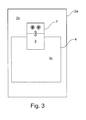
- FIGS. 1 to 3 an exemplary example of a coupling device 6 according to the invention is shown on a piece of furniture 1, with which an inner drawer 3 can be coupled to an outer drawer 2 for entrainment, in particular when the outer drawer is pulled out. From the furniture 1 are in FIG. 1 only the inner drawer 3 and partially a front panel 2a of the outer drawer 2 shown.
- an actuating element 7 of the coupling device 6 is slidably mounted on an area portion 2b of the inside of the front panel 2a.
- the actuator 7 is mounted vertically displaceable on the inside of the front panel 2a.
- a pivot bearing 11 is formed, on which a driving lever 8 is pivotally connected to the actuating element 7.
- the driving lever 8 is mounted about a horizontal axis of rotation up and down pivotally mounted on the pivot bearing 11.
- Fig.1 the take-off lever 8 is shown in an upwardly pivoted standby position, wherein the same driving lever is represented by the reference numeral 8 'in a position coupling the inner load 3 to the outer load 2.
- a hook member 9 At a free-standing end portion of the driving lever 8, a hook member 9. In the coupling position of the driving lever 8 ', the same hook element 9' is provided to engage behind a front panel 4 of the inner tray 3. By concerns on an inner surface portion 4c of the front panel 4, the hook member 9 'in the coupling position, the inner tray 3 move along when the outer tray 2 is pulled out of the furniture 1.
- a coupled state is from a perspective looking at the furniture 1 from inside to outside FIG. 3 shown.
- the driving lever 8 is in particular fixedly connected to an activation lever 10, wherein the activation lever 10 and the driving lever 8 are preferably formed as a one-piece component.
- the activation lever 10 By the connection of the activation lever 10 with the driving lever 8 an immediate movement coupling of the two levers 8 and 10 is provided.
- the activating lever 10 When the driving lever 8 is in the standby position, the activating lever 10 is disposed with a free-standing end portion protruding from the inward facing area 2b of the front panel 2a of the outside tray 2.
- the front panel 4 of the inner drawer and the front panel 2a of the outer drawer 2 are approximated to one another such that the same activation lever 10 'rests in parallel on both front panels 2 and 4.
- Fig.2 is a section of Fig.l shown with further details.
- the actuator 7 is pressed by means of a spring 13 down and can be to release a coupling of the inner tray 3 to the outer drawer 2 pull against the force of the spring 13 upwards, at the same time the driving lever 8 and the activation lever 10 are moved upward.
- the activation lever 10 engages as a spring means, for example, a compression spring 12 which holds the activation lever 10 yielding in a protruding from the inner surface portion 2b position. Due to the connection of the activation lever 10 with the driving lever 8 thereby the driving lever 8 is held in the standby position for coupling the inner tray 3. In the course of coupling the inner drawer 3, the front panel 4 approaches the front panel 2a, thereby pivoting the activation lever 10 down into a position parallel between two front panels 2a and 4. Due to the movement coupling with the activation lever 10 of the driving lever 8 is moved down and the hook member 9 behind the front panel 4 of the inner tray 3.
- a spring means for example, a compression spring 12 which holds the activation lever 10 yielding in a protruding from the inner surface portion 2b position. Due to the connection of the activation lever 10 with the driving lever 8 thereby the driving lever 8 is held in the standby position for coupling the inner tray 3. In the course of coupling the inner drawer 3, the front panel 4 approaches the front panel 2a
- Fig.2 are an upper altitude B and lower altitude C a top 4b of the front panel 4 of the inner tray 3 with respect to a position A of the pivot bearing 11 shown.
- the altitude B may correspond to a less heavily loaded state of the inner tray 3 than the altitude C.
- the actuating element 7 is located in a downwardly pressed position on the front panel 2a of the outer drawer 2, which is required in particular for the ready position of the driving lever 8.
- the coupling device 6 is mounted on the front panel 2 a such that a coupling of the inner tray 3 at both altitudes B and C is possible.
- the activation lever 10 When the inner tray 3 is in the high position C, only the activation lever 10 and the outer surface area 4 a of the front panel 4 of the inner tray 3 are in contact with a coupling.
- the front panel 4 When the inner tray 3 is in the high position B, the front panel 4 may be simultaneously in contact with the driving lever 8 and the activation lever 10.
- the activation lever 10 is formed so long in particular in the longitudinal direction that with the contact point of the activation lever 10, a greater lever moment is achievable, as with a contact point of the driving lever 8, which is struck by an upper edge 4d of the front panel. As a result, the driving lever 8 can be supported on the upper edge 4d.
- the coupling device 6 offers the advantage that the coupling device 6 makes it possible to couple the inner load 3 to the outer load 2 in, for example, different loading states of the inner load 3 and outer load 2.
Landscapes
- Drawers Of Furniture (AREA)
Applications Claiming Priority (1)
| Application Number | Priority Date | Filing Date | Title |
|---|---|---|---|
| DE202014102934.6U DE202014102934U1 (de) | 2014-06-27 | 2014-06-27 | Vorrichtung zur lösbaren Kopplung einer Außenlade mit einer Innenlade sowie ein Möbel |
Publications (2)
| Publication Number | Publication Date |
|---|---|
| EP2959800A1 true EP2959800A1 (fr) | 2015-12-30 |
| EP2959800B1 EP2959800B1 (fr) | 2017-08-30 |
Family
ID=53442619
Family Applications (1)
| Application Number | Title | Priority Date | Filing Date |
|---|---|---|---|
| EP15172727.8A Not-in-force EP2959800B1 (fr) | 2014-06-27 | 2015-06-18 | Meuble avec un dispositif destiné à l'accouplement amovible d'un chargeur intérieur sur un chargeur extérieur d'un meuble |
Country Status (3)
| Country | Link |
|---|---|
| EP (1) | EP2959800B1 (fr) |
| DE (1) | DE202014102934U1 (fr) |
| ES (1) | ES2650248T3 (fr) |
Families Citing this family (3)
| Publication number | Priority date | Publication date | Assignee | Title |
|---|---|---|---|---|
| DE102019117736A1 (de) * | 2019-07-01 | 2021-01-07 | Paul Hettich Gmbh & Co. Kg | Innenschubkasten und Möbel oder Haushaltsgerät |
| DE102019124130B4 (de) * | 2019-09-09 | 2022-12-15 | Vauth-Sagel Holding Gmbh & Co. Kg | Deaktivierbarer Auszugmitnehmer zur Montage an einer mehrere Auszüge abdeckenden Frontblende |
| US20250376881A1 (en) * | 2024-06-11 | 2025-12-11 | Textron Aviation Inc. | Touch latch drawer assemblies with unintentional anti-unlatching capability |
Citations (2)
| Publication number | Priority date | Publication date | Assignee | Title |
|---|---|---|---|---|
| JP2002320527A (ja) * | 2001-04-25 | 2002-11-05 | Kurogane Kosakusho Ltd | キャビネット |
| DE202012012266U1 (de) * | 2012-12-21 | 2014-03-24 | Grass Gmbh | Vorrichtung zur lösbaren Kopplung einer Innenlade an einer Außenlade eines Möbels sowie Möbel |
Family Cites Families (8)
| Publication number | Priority date | Publication date | Assignee | Title |
|---|---|---|---|---|
| CH203652A (de) * | 1938-07-04 | 1939-03-31 | Bezzola Werner | Selbsttätig einklinkende Klaue zum Festhalten offener Fensterläden beliebiger Dicke. |
| DE8802343U1 (de) * | 1988-02-23 | 1988-03-31 | SieMatic Möbelwerke GmbH & Co, 4972 Löhne | Auszug mit ankoppelbarem Schubkasten |
| FR2790030B1 (fr) * | 1999-02-19 | 2001-05-18 | Tordo Belgrano Sa | Dispositif de maintien en position ouverte notamment d'un vantail |
| EP1950370A1 (fr) * | 2007-01-26 | 2008-07-30 | Santino Brunetto | Dispositif de verrouillage pour portes, volets et similaires |
| ATE541106T1 (de) * | 2008-10-06 | 2012-01-15 | Santino Brunetto | Automatische vorrichtung zum sperren von türblättern oder fenstern und dergleichen |
| KR20110010405A (ko) * | 2009-07-24 | 2011-02-01 | 엘지전자 주식회사 | 냉장고 |
| FR2955136B1 (fr) * | 2010-01-14 | 2012-01-20 | Tordo Belgrano Sa | Arret de vantail |
| JP5912063B2 (ja) * | 2012-05-28 | 2016-04-27 | 株式会社ノーリツ | 引出しキャビネット |
-
2014
- 2014-06-27 DE DE202014102934.6U patent/DE202014102934U1/de not_active Expired - Lifetime
-
2015
- 2015-06-18 EP EP15172727.8A patent/EP2959800B1/fr not_active Not-in-force
- 2015-06-18 ES ES15172727.8T patent/ES2650248T3/es active Active
Patent Citations (2)
| Publication number | Priority date | Publication date | Assignee | Title |
|---|---|---|---|---|
| JP2002320527A (ja) * | 2001-04-25 | 2002-11-05 | Kurogane Kosakusho Ltd | キャビネット |
| DE202012012266U1 (de) * | 2012-12-21 | 2014-03-24 | Grass Gmbh | Vorrichtung zur lösbaren Kopplung einer Innenlade an einer Außenlade eines Möbels sowie Möbel |
Also Published As
| Publication number | Publication date |
|---|---|
| EP2959800B1 (fr) | 2017-08-30 |
| DE202014102934U1 (de) | 2015-10-02 |
| ES2650248T3 (es) | 2018-01-17 |
Similar Documents
| Publication | Publication Date | Title |
|---|---|---|
| EP2642891B1 (fr) | Adaptateur de châssis avec ferrure d'assemblage | |
| AT501468B1 (de) | Schwenkschiebetür | |
| DE202010008630U1 (de) | Liftschachttür-Entriegelung | |
| DE102010007129A1 (de) | Beschlag für Eckschränke | |
| AT517810A1 (de) | Überkopf-Gepäckfach | |
| EP3153064A1 (fr) | Dispositif de connexion amovible pour un tiroir mobile guidé par une unité de guidage dans une carcasse de meuble | |
| EP4077844B1 (fr) | Dispositif pour guider une porte coulissante ou une porte accordéon | |
| EP2959800B1 (fr) | Meuble avec un dispositif destiné à l'accouplement amovible d'un chargeur intérieur sur un chargeur extérieur d'un meuble | |
| WO2017036795A1 (fr) | Dispositif de positionnement de deux portes coulissantes et meuble | |
| AT506436B1 (de) | Vorrichtung zur regelung der öffnungsfolge von zweiflügeligen schwenktüren | |
| DE202010016904U1 (de) | Thekeneinsatz | |
| EP3354321A1 (fr) | Extincteurs à main | |
| EP3684223B1 (fr) | Dispositif d'accouplement destiné à un tiroir à encliquetage postérieur | |
| AT504314A1 (de) | Verfahren zur regelung der öffnungsfolge von zweiflügeligen schwenktüren | |
| DE102011006011A1 (de) | Fahrzeug | |
| EP2353439A1 (fr) | Armature pour une armoire angulaire | |
| EP3675691B1 (fr) | Dispositif d'insertion permettant d'insérer une partie mobile d'un meuble ou d'un appareil ménager dans une position finale | |
| DE102014009465B4 (de) | Aufnahmevorrichtung mit Deckel für den Innenraum eines Fahrzeugs | |
| DE102012222983A1 (de) | Verschwenkbare Armlehne, insbesondere Mittelarmlehne für ein Kraftfahrzeug | |
| EP2741015B1 (fr) | Porte pour un appareil ménager comprenant une partie de préhension de type plaque et un système d'ouverture de la partie de préhension, appareil ménager doté d'une telle porte et procédé d'ouverture d'une porte d'un appareil ménager | |
| EP2468146B1 (fr) | Meuble d'exposition refrigéré | |
| DE102013016069A1 (de) | Türgriff | |
| EP2884188B1 (fr) | Appareil ménager doté d'une porte escamotable dans un espace de rangement et d'un axe de rotation déplaçable en translation d'une unité de roulement et procédé d'ouverture et de fermeture d'une telle porte | |
| WO2013092164A1 (fr) | Couplage entre porte de cabine et porte palière | |
| EP1068797A2 (fr) | Dispositif de mélange et de distribution d'alimentation |
Legal Events
| Date | Code | Title | Description |
|---|---|---|---|
| PUAI | Public reference made under article 153(3) epc to a published international application that has entered the european phase |
Free format text: ORIGINAL CODE: 0009012 |
|
| AK | Designated contracting states |
Kind code of ref document: A1 Designated state(s): AL AT BE BG CH CY CZ DE DK EE ES FI FR GB GR HR HU IE IS IT LI LT LU LV MC MK MT NL NO PL PT RO RS SE SI SK SM TR |
|
| AX | Request for extension of the european patent |
Extension state: BA ME |
|
| 17P | Request for examination filed |
Effective date: 20160622 |
|
| RBV | Designated contracting states (corrected) |
Designated state(s): AL AT BE BG CH CY CZ DE DK EE ES FI FR GB GR HR HU IE IS IT LI LT LU LV MC MK MT NL NO PL PT RO RS SE SI SK SM TR |
|
| 17Q | First examination report despatched |
Effective date: 20160831 |
|
| STAA | Information on the status of an ep patent application or granted ep patent |
Free format text: STATUS: EXAMINATION IS IN PROGRESS |
|
| GRAP | Despatch of communication of intention to grant a patent |
Free format text: ORIGINAL CODE: EPIDOSNIGR1 |
|
| STAA | Information on the status of an ep patent application or granted ep patent |
Free format text: STATUS: GRANT OF PATENT IS INTENDED |
|
| GRAJ | Information related to disapproval of communication of intention to grant by the applicant or resumption of examination proceedings by the epo deleted |
Free format text: ORIGINAL CODE: EPIDOSDIGR1 |
|
| STAA | Information on the status of an ep patent application or granted ep patent |
Free format text: STATUS: EXAMINATION IS IN PROGRESS |
|
| REG | Reference to a national code |
Ref country code: DE Ref legal event code: R079 Ref document number: 502015001777 Country of ref document: DE Free format text: PREVIOUS MAIN CLASS: A47B0088020000 Ipc: A47B0088750000 |
|
| INTG | Intention to grant announced |
Effective date: 20170209 |
|
| RIC1 | Information provided on ipc code assigned before grant |
Ipc: A47B 88/75 20170101AFI20170208BHEP |
|
| GRAP | Despatch of communication of intention to grant a patent |
Free format text: ORIGINAL CODE: EPIDOSNIGR1 |
|
| STAA | Information on the status of an ep patent application or granted ep patent |
Free format text: STATUS: GRANT OF PATENT IS INTENDED |
|
| INTC | Intention to grant announced (deleted) | ||
| RIC1 | Information provided on ipc code assigned before grant |
Ipc: A47B 88/75 20170101AFI20170302BHEP |
|
| INTG | Intention to grant announced |
Effective date: 20170404 |
|
| GRAS | Grant fee paid |
Free format text: ORIGINAL CODE: EPIDOSNIGR3 |
|
| GRAA | (expected) grant |
Free format text: ORIGINAL CODE: 0009210 |
|
| STAA | Information on the status of an ep patent application or granted ep patent |
Free format text: STATUS: THE PATENT HAS BEEN GRANTED |
|
| AK | Designated contracting states |
Kind code of ref document: B1 Designated state(s): AL AT BE BG CH CY CZ DE DK EE ES FI FR GB GR HR HU IE IS IT LI LT LU LV MC MK MT NL NO PL PT RO RS SE SI SK SM TR |
|
| REG | Reference to a national code |
Ref country code: GB Ref legal event code: FG4D Free format text: NOT ENGLISH |
|
| REG | Reference to a national code |
Ref country code: CH Ref legal event code: EP |
|
| REG | Reference to a national code |
Ref country code: AT Ref legal event code: REF Ref document number: 922676 Country of ref document: AT Kind code of ref document: T Effective date: 20170915 |
|
| REG | Reference to a national code |
Ref country code: IE Ref legal event code: FG4D Free format text: LANGUAGE OF EP DOCUMENT: GERMAN |
|
| REG | Reference to a national code |
Ref country code: DE Ref legal event code: R096 Ref document number: 502015001777 Country of ref document: DE |
|
| REG | Reference to a national code |
Ref country code: NL Ref legal event code: MP Effective date: 20170830 |
|
| REG | Reference to a national code |
Ref country code: LT Ref legal event code: MG4D |
|
| REG | Reference to a national code |
Ref country code: ES Ref legal event code: FG2A Ref document number: 2650248 Country of ref document: ES Kind code of ref document: T3 Effective date: 20180117 |
|
| PG25 | Lapsed in a contracting state [announced via postgrant information from national office to epo] |
Ref country code: LT Free format text: LAPSE BECAUSE OF FAILURE TO SUBMIT A TRANSLATION OF THE DESCRIPTION OR TO PAY THE FEE WITHIN THE PRESCRIBED TIME-LIMIT Effective date: 20170830 Ref country code: FI Free format text: LAPSE BECAUSE OF FAILURE TO SUBMIT A TRANSLATION OF THE DESCRIPTION OR TO PAY THE FEE WITHIN THE PRESCRIBED TIME-LIMIT Effective date: 20170830 Ref country code: HR Free format text: LAPSE BECAUSE OF FAILURE TO SUBMIT A TRANSLATION OF THE DESCRIPTION OR TO PAY THE FEE WITHIN THE PRESCRIBED TIME-LIMIT Effective date: 20170830 Ref country code: SE Free format text: LAPSE BECAUSE OF FAILURE TO SUBMIT A TRANSLATION OF THE DESCRIPTION OR TO PAY THE FEE WITHIN THE PRESCRIBED TIME-LIMIT Effective date: 20170830 Ref country code: NO Free format text: LAPSE BECAUSE OF FAILURE TO SUBMIT A TRANSLATION OF THE DESCRIPTION OR TO PAY THE FEE WITHIN THE PRESCRIBED TIME-LIMIT Effective date: 20171130 |
|
| PG25 | Lapsed in a contracting state [announced via postgrant information from national office to epo] |
Ref country code: GR Free format text: LAPSE BECAUSE OF FAILURE TO SUBMIT A TRANSLATION OF THE DESCRIPTION OR TO PAY THE FEE WITHIN THE PRESCRIBED TIME-LIMIT Effective date: 20171201 Ref country code: RS Free format text: LAPSE BECAUSE OF FAILURE TO SUBMIT A TRANSLATION OF THE DESCRIPTION OR TO PAY THE FEE WITHIN THE PRESCRIBED TIME-LIMIT Effective date: 20170830 Ref country code: IS Free format text: LAPSE BECAUSE OF FAILURE TO SUBMIT A TRANSLATION OF THE DESCRIPTION OR TO PAY THE FEE WITHIN THE PRESCRIBED TIME-LIMIT Effective date: 20171230 Ref country code: LV Free format text: LAPSE BECAUSE OF FAILURE TO SUBMIT A TRANSLATION OF THE DESCRIPTION OR TO PAY THE FEE WITHIN THE PRESCRIBED TIME-LIMIT Effective date: 20170830 Ref country code: BG Free format text: LAPSE BECAUSE OF FAILURE TO SUBMIT A TRANSLATION OF THE DESCRIPTION OR TO PAY THE FEE WITHIN THE PRESCRIBED TIME-LIMIT Effective date: 20171130 |
|
| PG25 | Lapsed in a contracting state [announced via postgrant information from national office to epo] |
Ref country code: NL Free format text: LAPSE BECAUSE OF FAILURE TO SUBMIT A TRANSLATION OF THE DESCRIPTION OR TO PAY THE FEE WITHIN THE PRESCRIBED TIME-LIMIT Effective date: 20170830 |
|
| PG25 | Lapsed in a contracting state [announced via postgrant information from national office to epo] |
Ref country code: CZ Free format text: LAPSE BECAUSE OF FAILURE TO SUBMIT A TRANSLATION OF THE DESCRIPTION OR TO PAY THE FEE WITHIN THE PRESCRIBED TIME-LIMIT Effective date: 20170830 Ref country code: RO Free format text: LAPSE BECAUSE OF FAILURE TO SUBMIT A TRANSLATION OF THE DESCRIPTION OR TO PAY THE FEE WITHIN THE PRESCRIBED TIME-LIMIT Effective date: 20170830 Ref country code: PL Free format text: LAPSE BECAUSE OF FAILURE TO SUBMIT A TRANSLATION OF THE DESCRIPTION OR TO PAY THE FEE WITHIN THE PRESCRIBED TIME-LIMIT Effective date: 20170830 Ref country code: DK Free format text: LAPSE BECAUSE OF FAILURE TO SUBMIT A TRANSLATION OF THE DESCRIPTION OR TO PAY THE FEE WITHIN THE PRESCRIBED TIME-LIMIT Effective date: 20170830 |
|
| PG25 | Lapsed in a contracting state [announced via postgrant information from national office to epo] |
Ref country code: SK Free format text: LAPSE BECAUSE OF FAILURE TO SUBMIT A TRANSLATION OF THE DESCRIPTION OR TO PAY THE FEE WITHIN THE PRESCRIBED TIME-LIMIT Effective date: 20170830 Ref country code: IT Free format text: LAPSE BECAUSE OF FAILURE TO SUBMIT A TRANSLATION OF THE DESCRIPTION OR TO PAY THE FEE WITHIN THE PRESCRIBED TIME-LIMIT Effective date: 20170830 Ref country code: EE Free format text: LAPSE BECAUSE OF FAILURE TO SUBMIT A TRANSLATION OF THE DESCRIPTION OR TO PAY THE FEE WITHIN THE PRESCRIBED TIME-LIMIT Effective date: 20170830 Ref country code: SM Free format text: LAPSE BECAUSE OF FAILURE TO SUBMIT A TRANSLATION OF THE DESCRIPTION OR TO PAY THE FEE WITHIN THE PRESCRIBED TIME-LIMIT Effective date: 20170830 |
|
| REG | Reference to a national code |
Ref country code: DE Ref legal event code: R097 Ref document number: 502015001777 Country of ref document: DE |
|
| PLBE | No opposition filed within time limit |
Free format text: ORIGINAL CODE: 0009261 |
|
| STAA | Information on the status of an ep patent application or granted ep patent |
Free format text: STATUS: NO OPPOSITION FILED WITHIN TIME LIMIT |
|
| 26N | No opposition filed |
Effective date: 20180531 |
|
| PG25 | Lapsed in a contracting state [announced via postgrant information from national office to epo] |
Ref country code: SI Free format text: LAPSE BECAUSE OF FAILURE TO SUBMIT A TRANSLATION OF THE DESCRIPTION OR TO PAY THE FEE WITHIN THE PRESCRIBED TIME-LIMIT Effective date: 20170830 |
|
| PG25 | Lapsed in a contracting state [announced via postgrant information from national office to epo] |
Ref country code: MT Free format text: LAPSE BECAUSE OF FAILURE TO SUBMIT A TRANSLATION OF THE DESCRIPTION OR TO PAY THE FEE WITHIN THE PRESCRIBED TIME-LIMIT Effective date: 20170830 |
|
| REG | Reference to a national code |
Ref country code: CH Ref legal event code: PL |
|
| REG | Reference to a national code |
Ref country code: BE Ref legal event code: MM Effective date: 20180630 |
|
| REG | Reference to a national code |
Ref country code: IE Ref legal event code: MM4A |
|
| PG25 | Lapsed in a contracting state [announced via postgrant information from national office to epo] |
Ref country code: MC Free format text: LAPSE BECAUSE OF FAILURE TO SUBMIT A TRANSLATION OF THE DESCRIPTION OR TO PAY THE FEE WITHIN THE PRESCRIBED TIME-LIMIT Effective date: 20170830 Ref country code: LU Free format text: LAPSE BECAUSE OF NON-PAYMENT OF DUE FEES Effective date: 20180618 |
|
| PG25 | Lapsed in a contracting state [announced via postgrant information from national office to epo] |
Ref country code: IE Free format text: LAPSE BECAUSE OF NON-PAYMENT OF DUE FEES Effective date: 20180618 Ref country code: FR Free format text: LAPSE BECAUSE OF NON-PAYMENT OF DUE FEES Effective date: 20180630 Ref country code: LI Free format text: LAPSE BECAUSE OF NON-PAYMENT OF DUE FEES Effective date: 20180630 Ref country code: CH Free format text: LAPSE BECAUSE OF NON-PAYMENT OF DUE FEES Effective date: 20180630 |
|
| PG25 | Lapsed in a contracting state [announced via postgrant information from national office to epo] |
Ref country code: BE Free format text: LAPSE BECAUSE OF NON-PAYMENT OF DUE FEES Effective date: 20180630 |
|
| REG | Reference to a national code |
Ref country code: ES Ref legal event code: FD2A Effective date: 20190916 |
|
| PG25 | Lapsed in a contracting state [announced via postgrant information from national office to epo] |
Ref country code: ES Free format text: LAPSE BECAUSE OF NON-PAYMENT OF DUE FEES Effective date: 20180619 |
|
| GBPC | Gb: european patent ceased through non-payment of renewal fee |
Effective date: 20190618 |
|
| PG25 | Lapsed in a contracting state [announced via postgrant information from national office to epo] |
Ref country code: GB Free format text: LAPSE BECAUSE OF NON-PAYMENT OF DUE FEES Effective date: 20190618 |
|
| PG25 | Lapsed in a contracting state [announced via postgrant information from national office to epo] |
Ref country code: PT Free format text: LAPSE BECAUSE OF FAILURE TO SUBMIT A TRANSLATION OF THE DESCRIPTION OR TO PAY THE FEE WITHIN THE PRESCRIBED TIME-LIMIT Effective date: 20170830 |
|
| PG25 | Lapsed in a contracting state [announced via postgrant information from national office to epo] |
Ref country code: MK Free format text: LAPSE BECAUSE OF NON-PAYMENT OF DUE FEES Effective date: 20170830 Ref country code: CY Free format text: LAPSE BECAUSE OF FAILURE TO SUBMIT A TRANSLATION OF THE DESCRIPTION OR TO PAY THE FEE WITHIN THE PRESCRIBED TIME-LIMIT Effective date: 20170830 Ref country code: HU Free format text: LAPSE BECAUSE OF FAILURE TO SUBMIT A TRANSLATION OF THE DESCRIPTION OR TO PAY THE FEE WITHIN THE PRESCRIBED TIME-LIMIT; INVALID AB INITIO Effective date: 20150618 |
|
| PG25 | Lapsed in a contracting state [announced via postgrant information from national office to epo] |
Ref country code: AL Free format text: LAPSE BECAUSE OF FAILURE TO SUBMIT A TRANSLATION OF THE DESCRIPTION OR TO PAY THE FEE WITHIN THE PRESCRIBED TIME-LIMIT Effective date: 20170830 |
|
| PGFP | Annual fee paid to national office [announced via postgrant information from national office to epo] |
Ref country code: TR Payment date: 20200417 Year of fee payment: 6 |
|
| PGFP | Annual fee paid to national office [announced via postgrant information from national office to epo] |
Ref country code: DE Payment date: 20220426 Year of fee payment: 8 |
|
| PGFP | Annual fee paid to national office [announced via postgrant information from national office to epo] |
Ref country code: AT Payment date: 20220428 Year of fee payment: 8 |
|
| REG | Reference to a national code |
Ref country code: DE Ref legal event code: R119 Ref document number: 502015001777 Country of ref document: DE |
|
| REG | Reference to a national code |
Ref country code: AT Ref legal event code: MM01 Ref document number: 922676 Country of ref document: AT Kind code of ref document: T Effective date: 20230618 |
|
| PG25 | Lapsed in a contracting state [announced via postgrant information from national office to epo] |
Ref country code: AT Free format text: LAPSE BECAUSE OF NON-PAYMENT OF DUE FEES Effective date: 20230618 |
|
| PG25 | Lapsed in a contracting state [announced via postgrant information from national office to epo] |
Ref country code: DE Free format text: LAPSE BECAUSE OF NON-PAYMENT OF DUE FEES Effective date: 20240103 Ref country code: AT Free format text: LAPSE BECAUSE OF NON-PAYMENT OF DUE FEES Effective date: 20230618 |
|
| PG25 | Lapsed in a contracting state [announced via postgrant information from national office to epo] |
Ref country code: TR Free format text: LAPSE BECAUSE OF NON-PAYMENT OF DUE FEES Effective date: 20210618 |