EP2959802A1 - Dispositif destine a l'application d'une unite de guidage sur une partie de meuble - Google Patents
Dispositif destine a l'application d'une unite de guidage sur une partie de meuble Download PDFInfo
- Publication number
- EP2959802A1 EP2959802A1 EP15172728.6A EP15172728A EP2959802A1 EP 2959802 A1 EP2959802 A1 EP 2959802A1 EP 15172728 A EP15172728 A EP 15172728A EP 2959802 A1 EP2959802 A1 EP 2959802A1
- Authority
- EP
- European Patent Office
- Prior art keywords
- furniture part
- abutment
- attachment
- movement rail
- abutment sections
- Prior art date
- Legal status (The legal status is an assumption and is not a legal conclusion. Google has not performed a legal analysis and makes no representation as to the accuracy of the status listed.)
- Granted
Links
Images
Classifications
-
- F—MECHANICAL ENGINEERING; LIGHTING; HEATING; WEAPONS; BLASTING
- F16—ENGINEERING ELEMENTS AND UNITS; GENERAL MEASURES FOR PRODUCING AND MAINTAINING EFFECTIVE FUNCTIONING OF MACHINES OR INSTALLATIONS; THERMAL INSULATION IN GENERAL
- F16B—DEVICES FOR FASTENING OR SECURING CONSTRUCTIONAL ELEMENTS OR MACHINE PARTS TOGETHER, e.g. NAILS, BOLTS, CIRCLIPS, CLAMPS, CLIPS OR WEDGES; JOINTS OR JOINTING
- F16B12/00—Jointing of furniture or the like, e.g. hidden from exterior
- F16B12/04—Non-loosenable joints for non-metal furniture parts, e.g. glued
-
- A—HUMAN NECESSITIES
- A47—FURNITURE; DOMESTIC ARTICLES OR APPLIANCES; COFFEE MILLS; SPICE MILLS; SUCTION CLEANERS IN GENERAL
- A47B—TABLES; DESKS; OFFICE FURNITURE; CABINETS; DRAWERS; GENERAL DETAILS OF FURNITURE
- A47B88/00—Drawers for tables, cabinets or like furniture; Guides for drawers
- A47B88/40—Sliding drawers; Slides or guides therefor
- A47B88/423—Fastening devices for slides or guides
- A47B88/427—Fastening devices for slides or guides at drawer side
Definitions
- the invention relates to a device for attaching a guide unit to a furniture part according to the preamble of claim 1 and a piece of furniture.
- the present invention has for its object to provide a device for attaching a guide unit, which offers improved positioning with a relatively simple attachment.
- the invention relates to a device for attaching a guide unit on a first furniture part, which is movably guided relative to a second furniture part, wherein the guide unit comprises a arranged on the second furniture part carcass rail and arranged on the first furniture part movement rail from.
- the essence of the invention is that at a lower edge of the device, which is intended to be arranged on the movement rail, two abutment portions are arranged at a distance from each other, wherein each of the abutment portions is formed on a side facing the respective other abutment portion, so that between the abutment sections, the movement rail can be arranged, wherein at least one of the abutment portions is mounted on the device so adjustable that a position of the corresponding abutment portion is changeable to align in the assembled state, the first furniture part in a horizontal direction with respect to the movement rail can.
- This offers the advantage that it is possible to limit or completely avoid a lateral movement play of the first furniture part on the movement rail.
- the first furniture part may be a furniture drawer, e.g. a drawer with a guide unit at a e.g. Furniture body as a second furniture part movably guided and in particular attached.
- the furniture body may be a body of e.g. a cabinet, e.g. a chest of drawers, e.g. a table or any furniture, which is designed in a similar manner for a movable storage and receiving a furniture drawer.
- the first furniture part may be movably guided on the second furniture part with two guide units, which are preferably mounted on opposite sides of the first furniture part, in particular with parallel guide paths.
- the lower edge is an outer edge of the device, preferably an outermost extension of the device one side, ie an outer side is limited and which is intended for a downward arrangement in an assembled state.
- the device is intended for mounting on the first furniture part, in which the lower edge of the movement rail and in particular an upper side of the movement rail is arranged facing.
- at least a portion of the lower edge is provided for a resting and in particular for a flat abutment against a surface of the movement rail.
- the device is preferably for mounting on a back side of the first furniture part, e.g. a drawer rear wall provided.
- the lower edge of the device is preferably arranged in the region of a lower edge of a rear wall of the first furniture part and can protrude downward in particular over the lower edge of the rear wall of the first furniture part, in particular if the stability or strength of the device is designed to the first furniture part eg in the area of the rear wall on the movement rail.
- a plurality of lower edges may be provided for resting the device.
- a plurality of the lower edges, and in particular all lower edges may lie in a common plane in order to distribute forces when resting relatively evenly on the plurality of lower edges.
- a plurality of lower edges, formed separately from one another may be provided in different, e.g. be arranged in mutually parallel positions so that e.g. in case of differently inclined attachments of the device only one lower edge can be selected for a resting.
- the lower edge defines a surface area which is intended for resting on the movement rail. If appropriate, this applies to a plurality of lower edges, each of which delimits one of a plurality of separate surface areas.
- the surface area may, for example, a portion of an end face on the corresponding outer side of the device limit.
- the lower edge can form an underside of the device.
- the lower edge and optionally an area bounded by the lower edge can be at least partially and in particular to a large extent - i. to more than half of a particular continuous longitudinal extension of the lower edge - under a center of gravity or a. be arranged geometric center of the device. Thereby a concentrated, e.g. unilateral power transmission avoidable, whereby the device is advantageous long lasting and usable.
- the lower edge is adapted to a shape of an upper side of the movement rail.
- the lower edge may optionally be straight and one of its limited surface area may be flat on the underside.
- the lower edge may be defined by e.g. a plurality of knobs, studs or similar protruding structures may be provided, which are used for resting on the motion rail.
- the lower edge can thus advantageously be e.g. be adapted to a roughened, in particular structured surface of the movement rail.
- the stopper portions may be formed, for example, as a flat surface, which are formed for example perpendicular to the particular straight lower edge of the device.
- the device only needs to be provided on one side of eg a rear wall of the first furniture part for attachment to a movement rail.
- a left side of the rear wall if the device according to the invention is mounted on the right side, can be provided for the first furniture part, for example, a relatively simply constructed and correspondingly inexpensive rail attachment component.
- it can be a component for attachment be dispensable entirely on the opposite side, if one or two movement rails, for example, located closer to a lying parallel to the direction of the central axis of a bottom than on the outer sides of side frames of the first furniture part.
- a preferred embodiment of the invention is that the positions of the abutment sections on the device are independently adjustable. This offers the advantage that the device can be used advantageously for different attachment positions of the movement rail on the first furniture part as well as for different movement rails with different widths, for example.
- the two positionable abutment sections can be adjustable with two identical or two different adjustment devices.
- At least one of the abutment sections is attached to a support element, which is designed to support the device on the movement rail.
- the lower edge of the support element may be provided and optionally together with the projection form a stop angle.
- the device can be simplified if the support element is in particular laterally displaceable connected to the device, so that e.g. a position of the abutment portion on an underside of the device is adjustable.
- the position of the two abutment sections on the device are coupled to each other adjustable. For example, this can be ensured by the fact that a lateral adjustment of one of the first abutment section basically entrains the second abutment section.
- a further preferred embodiment of the invention provides that the distance between the two abutment sections, in particular between abutment sections, is fixed.
- the device can advantageously stable To run.
- a distance between the abutment sections is adapted to a width of a movement rail, reliable positioning can thereby be ensured comparatively easily.
- the two abutment sections can be connected to one another via a displaceable connection yoke.
- the support element and the connection yoke can be integrally connected to each other in one piece, in particular from a material.
- the position of at least one of the abutment sections is adjustable by a set screw. This allows a positioning with a fixation or attachment and attachment combine.
- the position of at least one of the abutment sections can be adjusted by means of a rotary element having a helical setting contour.
- the rotary member may be rotatably mounted on the apparatus at a predetermined position, with an engaging portion of e.g. one of the abutment portions engages the spiraling control contour for positioning.
- One of the abutment sections or both abutment sections is also a rotary element with a center eccentrically arranged to the rotation center. can be used circular setting contour.
- the control contour can furthermore be elliptical.
- the setting contour can be shaped, for example, as a groove on an engaging side of the rotary member.
- a locking receptacle for a locking device of the movement rail is preferably formed on the support element. This allows degrees of freedom of a movement in particular sideways to restrict the extension direction of the furniture part.
- the Arretianss problem can for a play-free recording a portion of the locking device may be formed, whereby a positioning of the movement rail on the furniture element over a comparatively long service life can be ensured.
- the device preferably comprises a mounting element, which is provided for attachment of the device to the first furniture part.
- the mounting element may for example have a dowel or, for example, a bore for screwing the device on the first furniture part.
- At least one adjustable abutment section is displaceably mounted on the mounting element.
- one of the abutment sections can be displaceably mounted to the mounting element via an intermediate element, in particular on the intermediate element, as a result of which the abutment section can be positioned, for example, in different directions relative to the mounting element.
- the basic idea of the invention can be further developed in the direction of an attachment device which is equipped with two attachment units for attaching a guide device to a first furniture part.
- the furniture part is movably guided with two guide units of the guide device relative to a second furniture part, wherein each guide unit comprises a movement rail arranged on the first furniture part and wherein for each movement rail one of the attachment units is provided for attachment of the first furniture part to the corresponding guide unit.
- at least one of the two attachment units is a device according to the invention of the type described above.
- a first attachment device formed according to the invention can be provided for precise positioning in order to form a fixed bearing of the attachment device.
- the second attachment unit for a second movement rail can be made comparatively simpler, in particular without positionable abutment sections.
- the contact sections of the second attachment unit can be arranged, for example, at a distance, the example when setting the first attachment unit provides a movement of the furniture part to the second movement rail and, for example, during assembly of the furniture part to eg two guide units mounting movements limited so that the furniture part is relatively quickly and easily attached.
- both attachment units can be designed in the form of devices according to the invention, wherein the two attachment units are preferably mirror-symmetrical to one another.
- an attachment device according to the invention can advantageously be designed to save space, in particular in a flat construction.
- Adjusting screws or rotating elements with setting contours advantageously arrange so that they do not protrude laterally beyond a cross-sectional profile of the furniture part and thereby possibly disturbances, for example. allow movements of the furniture part during retraction and extension.
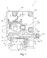
- FIG. 1 a first embodiment of a device 1 according to the invention is shown below as Mounting device 1 is called.
- the mounting device 1 is located on an attachment device 2d of a movement rail 2 at the rear end portion thereof.
- the movement rail 2 is the only part of a guide unit shown.
- the movement rail 2 has a rectangular, channel-shaped cross-sectional profile, which is bounded laterally by straight, vertical profile sections 2a and 2c.
- the vertical profile sections 2a and 2c are connected by a straight, horizontal profile section 2b, which limits the cross-sectional profile of the movement rail 2 upwards.
- the attachment device 2d forms a stop for attachment of a movable furniture part (not shown), by which a displacement of the furniture part is prevented when mounted over one end of the movement rail 2 addition.
- the mounting device 1 has a mounting plate 3, which is provided at several points with holes 3b, to screw the mounting device to a rear wall (not shown) of a movable furniture part, such as a drawer.
- the FIG. 1 shows a view of a rear side of the mounting device 1, whereby a back 3a of the mounting plate 3 is visible.
- an attachment side (not shown) is located on the mounting plate 3, which may be formed as an eg closed, flat surface for abutment with a rear wall (not shown) of a movable furniture part (not shown).
- the mounting plate 3 with the attachment side abut flat against the rear wall of the movable furniture part, when the mounting plate 3 is screwed to the holes 3b on the rear wall, for example.
- the attachment side may provide a plane for abutment on a furniture part, over which no portion of the mounting device 1 protrudes in the direction perpendicular to the plane on the attachment side, to avoid associated limitations in mounting the mounting device 1 on the back of the furniture part.
- the mounting device 1 has a height adjustment device 4, which comprises a vertically slidably mounted on the mounting plate 3 support plate 5.
- a height adjustment device 4 which comprises a vertically slidably mounted on the mounting plate 3 support plate 5.
- vertical displacements of the support plate 5 are e.g. on a guide projection 3c - here for example in the form of a straight, vertically extended bar - the mounting plate 3 out.
- an adjusting lever 6 is rotatably mounted such that supporting forces from the adjusting lever 6 on the support plate 5 are transferable.
- a sliding bolt 7 is attached, which extends through the support plate 5 and engages in the mounting plate 3 such that on the sliding bolt 7 supporting forces from the adjusting lever 6 are transferable to the mounting plate.
- the sliding bolt 7 is arranged on the adjusting lever 6 eccentrically to a center of rotation of the actuating lever 6. Due to the eccentric arrangement of the sliding bolt 7 on the adjusting lever 6, the support plate 5 and the mounting plate 3 by pivoting the adjusting lever 6 to each other in the vertical direction V adjustable.
- a straight bottom edge 8, which is designed to rest on the movement rail 2, is formed via a central section on an underside of the support plate 5.
- the lower edge 8 is bounded on the left side by a projection 9, projects from the support plate 5 down.
- a contact surface 10 of the projection 9 facing the profile section 2 a of the movement rail 2 is arranged at right angles to the lower edge 8. As a result, the contact surface 10 can be arranged plane-parallel to the profile section 2a of the movement rail 2.
- the support element 5 is extended in a lower region to the right by a beam section 11.
- a right part of the beam portion 11 is formed as a cylindrical threaded bolt 11a, on the screw a knurled nut 12.
- the lower edge 8 is extended.
- a carriage member 13 is attached, for example, which is guided on the beam portion 11.
- a groove 12 a is formed, which is provided for engagement of an engagement portion 13 a of the carriage member 13.
- a bottom of the carriage member 13 projects a projection 14 down.
- a vertical planar contact portion 15 is formed.
- the abutment sections 10 and 15 are formed plane-parallel to each other, whereby both abutment sections 10, 15 can lie flat against the movement rail 2 at the same time.
- both abutment sections 10 and 15 are provided with flat surfaces for engagement with the movement rail 2.
- at least one of the abutment sections 10, 15 may be formed as an edge.
- the course and shape of the contact sections 10 and 15 are adapted to the respective cross-sectional profile of the movement rail 2.
- the mounting device 1 Before mounting a furniture part (not shown) on the movement rail 2, which may eg be mounted together with a remaining guide unit (not shown) in a furniture body (not shown), the mounting device 1 by screwing the mounting plate 3 on a rear wall (not shown) of the furniture part attached. By turning the knurled nut 12, the right abutment portion 15 can be positioned at a distance from the left abutment portion 10 which is larger than a width B of the movement rail 2. As a result, the furniture part with the mounting device 1 can be relatively easily pushed along the movement rail 2 until the mounting device 1 strikes the attachment device 2d.
- the mounting device 1 is part of a mounting system, of which only the mounting device 1 is shown here.
- the mounting system may comprise a second mounting device (not shown) according to the invention, which is constructed in mirror image to the mounting device 1.
- the second mounting device is designed such a mirror image that it is e.g. by reflection on a plane perpendicular to the flat surface on the mounting side of the mounting plate and parallel to e.g. to the lateral edge 3d or 3e arranged level emerges from the mounting device 1.
- This allows the mounting system e.g. symmetrical in particular without laterally projecting parts on a rear side of a movable furniture part, e.g. a drawer attach.
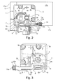
- FIGS. 2 and 3 a second embodiment of a mounting device 1 according to the invention is shown, wherein in Fig.2 an arrangement of the mounting device 1 is shown on a movable furniture part 17, in particular in the form of a drawer.
- the furniture part 17 has a side wall 17a and a rear wall 17b.
- a mounting plate 3 of the mounting device 1 on the rear wall 17b of the furniture part 17 with, for example screws (not shown) or eg nails (not shown) may be attached.
- the furniture part 17 is positioned and mounted with the mounting device 1 on a moving rail 2, wherein the movement rail 2 is the only one in the FIGS. 2 and 3 shown element of a guide unit is.
- the mounting device 1 has a height adjustment device 4, which substantially coincides with that of the first embodiment.
- a height adjustment device 4 is formed on an adjusting lever 6, a circular disk-shaped projection 6a is formed, with which the adjusting lever 6 is mounted in a circular opening 5a of a support plate 5.
- a sliding bolt 7 protrudes through the adjusting lever 6 and the support plate 5 and into a horizontally extended slot 3f of the mounting plate 3 inside.
- the sliding bolt 7 is movable about a common center of the circular-disc-shaped projection 6a and the opening 5a on a circular arc-shaped path, with the slot 3f a lateral movement play is provided on the mounting plate 3 for the sliding bolt 7.
- a lower edge 3g of the mounting plate and a lower edge 17c of the furniture part 17, which is connected to the mounting plate 3, via a lower edge 8 of the support plate 5 can be raised and vertically by locking the control lever 6, e.g. in one of the locking recesses 5b, positionable.
- the lower edge 8 is preferably supported on a horizontal, straight profile section 2 b of the movement rail 2, on which the lower edge 8 preferably rests or bears evenly.
- the height adjustment device 4 a position of the lower edge 8 of the support plate 5 above the lower edge 3g of the mounting plate 3 adjustable.
- the height adjustment device 4 can be relieved, if the mounting plate 3 in e.g. a suitable position on the rear wall 17 b is mounted, which requires no additional adjustment.
- both a first projection 9 as well a second projection 14 is connected to each other substantially rigidly via a connecting yoke 13b of a carriage member 13.
- a first contact section 10 and a second contact section 15 are arranged at a fixed distance from one another such that the movement rail 2 can be arranged between the contact sections 10 and 15.
- the carriage member 13 is coupled with an engaging portion 13a to an adjusting nut 12 on which a groove 12a for coupling engagement of the engaging portion 13a is provided.
- the adjusting nut 12 is screwed onto a threaded portion 11 a of a beam portion 11, with which the lower edge 8 of the support plate 5 is extended over at least an entire width of the horizontal profile section 2 b of the movement rail 2.
- the carriage element 13 By rotating the knurled nut 12, the carriage element 13 can be displaced and positioned relative to the support plate 5 along the lower edge 8, wherein positions of both abutment sections 10 and 15 are simultaneously variable. Because the abutment sections 10 and 15 can engage opposing sides on the movement rail 2, the mounting device 1 offers the possibility of adjusting a position of the furniture part 17 in opposite directions.
- the mounting device 1 can be used as an adjustable fixed bearing for a lateral positioning of the furniture part 17, whereby a second mounting device (not shown) , which is provided for a mounting of the furniture part on a second movement rail (not shown), as a movable bearing with a lateral movement play and possibly with at least one fixed contact portion (not shown) may be formed.
- An inventive mounting system - according to an attachment device according to claim 14 or 15 - with a first inventive and with a second, usable as a movable mounting device is comparatively easy and quick to attach and adjustable.
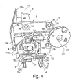
- FIG. 4 A third embodiment of a mounting device 1 according to the invention is shown in FIG FIG. 4 shown.
- the mounting device 1 is mounted on a movement rail 2 of a guide unit 18.
- the movement rail 2 is displaceable along a longitudinal axis of the guide unit 18, wherein the movement rail 2 indirectly or directly - for example via an intermediate rail (not shown) - is movably guided and supported on a carcass rail 18a.
- the movement rail 2 has at one end portion an attachment device 2d, whereby a mounting position for the mounting device 1 is predetermined.
- a receiving opening 16 is formed, which is preferably provided for a play-free engagement of the particular hook-shaped attachment device 2d.
- the mounting device 1 comprises a height adjustment device 4, with which a mounting plate 3 by turning an adjusting lever 6 in the vertical direction relative to a support plate 5 is displaced or adjustable.
- a difference from the second embodiment is that a sliding bolt 7 does not engage directly in the mounting plate 3 but in an intermediate plate 19.
- straight strip-shaped guide projections 3h are formed fixed, which run parallel to a straight horizontal lower edge 3g of the mounting plate 3. With the guide projections 3h, the intermediate plate 19 is guided horizontally slidably on the mounting plate 3, and an upper one of the guide projections 3h is provided and formed for transmitting support forces for vertical positioning of the mounting plate.
- intermediate plate 19 fixed guide projections 19b are formed, which extend straight in a mounted state of the mounting device 1 in the vertical direction.
- the guide projections 19b are on the intermediate plate 19th arranged and designed such that with these the support plate 5 is movably adjustable in the vertical direction.
- FIG. 4 shown mounting device 1 to the second embodiment is that a first projection 9 and a second projection 14 are fixedly formed on the support plate 5.
- the support plate 5 is extended at the lower edge 8 by a beam portion 11 to form the lower edge 8 over at least one horizontal width of the moving rail 2 for a close fit on a central profile section 2 b of the movement rail 2.
- the contact sections 10 and 15 are arranged at a fixed distance from each other along the lower edge 8, in which the mounting device 1 in the mounted state shown only a comparatively small lateral movement play relative to the movement rail 2 is available.
- the movement play can be less than e.g. 50% or e.g. 25%, better still less than 10%, in particular less than 5% and preferably less than 2% of a width of the movement rail 2, in particular in the region of the attachment device 2d.
- the guide projections 3h are extended beyond a lateral edge 3d of the mounting plate 3 protruding.
- the mounting plate 3 is also extended beyond the edge 3d in a region between the two guide projections 3h.
- a pivot pin 21 is mounted on the guide projections 3h, on which a thumbwheel 20 is mounted.
- the thumbwheel 20 has on a side facing the mounting plate 3 (not visible) on a control contour (not visible).
- the intermediate plate 19 has a laterally outstanding, strip-shaped beam portion 19 a, which is mounted laterally displaceable between the guide projections 3 h with respect to the mounting plate 3.
- An engagement structure (not shown), for example in the form of a pin (not shown) projecting into the setting wheel, is formed on a region of the beam section 19a of the intermediate plate 19 which is concealed by the setting wheel 20 and engages in the setting contour of the setting wheel 20, for example.
- the setting contour of the setting wheel 20 is designed such that by rotating the setting wheel 20, the engagement structure of the beam portion 19a and thus the intermediate plate 19 with the height adjustment device 4 in the horizontal direction parallel to the mounting plate 3 is adjustable.
Landscapes
- Engineering & Computer Science (AREA)
- General Engineering & Computer Science (AREA)
- Mechanical Engineering (AREA)
- Drawers Of Furniture (AREA)
Applications Claiming Priority (1)
| Application Number | Priority Date | Filing Date | Title |
|---|---|---|---|
| DE202014102893.5U DE202014102893U1 (de) | 2014-06-25 | 2014-06-25 | Vorrichtung zur Anbringung einer Führungseinheit an einem Möbelteil |
Publications (2)
| Publication Number | Publication Date |
|---|---|
| EP2959802A1 true EP2959802A1 (fr) | 2015-12-30 |
| EP2959802B1 EP2959802B1 (fr) | 2018-03-14 |
Family
ID=53510608
Family Applications (1)
| Application Number | Title | Priority Date | Filing Date |
|---|---|---|---|
| EP15172728.6A Active EP2959802B1 (fr) | 2014-06-25 | 2015-06-18 | Dispositif destine a l'application d'une unite de guidage sur une partie de meuble |
Country Status (3)
| Country | Link |
|---|---|
| US (1) | US10253798B2 (fr) |
| EP (1) | EP2959802B1 (fr) |
| DE (1) | DE202014102893U1 (fr) |
Families Citing this family (14)
| Publication number | Priority date | Publication date | Assignee | Title |
|---|---|---|---|---|
| DE102015106854A1 (de) * | 2015-05-04 | 2016-11-10 | Paul Hettich Gmbh & Co. Kg | Vorrichtung und Verfahren zum Festlegen eines Schubelementes |
| DE102015106855A1 (de) * | 2015-05-04 | 2016-11-10 | Paul Hettich Gmbh & Co. Kg | Vorrichtung und Verfahren zum Festlegen eines Schubelementes |
| DE102015106852A1 (de) * | 2015-05-04 | 2016-11-10 | Paul Hettich Gmbh & Co. Kg | Vorrichtung und Verfahren zum Festlegen eines Schubelementes |
| DE102015106873A1 (de) * | 2015-05-04 | 2016-11-10 | Paul Hettich Gmbh & Co. Kg | Vorrichtung und Verfahren zum Festlegen eines bewegbaren Möbelteils |
| DE102015106856A1 (de) * | 2015-05-04 | 2016-11-10 | Paul Hettich Gmbh & Co. Kg | Vorrichtung und Verfahren zum Festlegen eines Schubelementes |
| DE202015105679U1 (de) * | 2015-10-26 | 2017-01-27 | Grass Gmbh | Einstellmittel für eine Rastanordnung zur Einstellung eines an einem Möbelkorpus aufgenommenen bewegbaren Möbelteils |
| USD853828S1 (en) * | 2015-12-21 | 2019-07-16 | Grass Gmbh | Snap-on coupling |
| TWI605777B (zh) * | 2016-12-12 | 2017-11-21 | 川湖科技股份有限公司 | 滑軌機構及可用於滑軌的調整總成 |
| TWI616163B (zh) * | 2017-03-07 | 2018-03-01 | 川湖科技股份有限公司 | 用於傢俱部件的連接機構與滑軌總成 |
| TWI616164B (zh) * | 2017-03-07 | 2018-03-01 | 川湖科技股份有限公司 | 用於傢俱部件的連接機構與滑軌總成 |
| TWI646922B (zh) * | 2017-08-31 | 2019-01-11 | 川湖科技股份有限公司 | 滑軌機構及可用於滑軌的調整總成 |
| CN110720768B (zh) * | 2018-07-17 | 2022-05-13 | 川湖科技股份有限公司 | 用于可相对活动的物件的锁机构 |
| TWI670031B (zh) * | 2018-09-27 | 2019-09-01 | 川湖科技股份有限公司 | 滑軌機構 |
| DE102018130012A1 (de) * | 2018-11-27 | 2020-05-28 | Paul Hettich Gmbh & Co. Kg | Schubkasten und Möbel |
Citations (4)
| Publication number | Priority date | Publication date | Assignee | Title |
|---|---|---|---|---|
| DE3632442A1 (de) * | 1986-09-24 | 1988-03-31 | Lautenschlaeger Kg Karl | Beschlag fuer die verstellbare halterung der laufschiene einer schubladen-ausziehfuehrung |
| DE202006003035U1 (de) * | 2006-02-25 | 2007-07-05 | Alfit Ag | Vorrichtung für die verstellbare Halterung der Laufschiene von Ausziehführungen an Schubladen |
| DE202006006065U1 (de) * | 2006-04-13 | 2007-08-23 | Alfit Ag | Unterflur-Führungsanordnung für Möbelteile, insbesondere im Korpus von Möbelstücken |
| WO2012092634A1 (fr) * | 2011-01-05 | 2012-07-12 | Julius Blum Gmbh | Dispositif d'accouplement pour tiroirs |
Family Cites Families (9)
| Publication number | Priority date | Publication date | Assignee | Title |
|---|---|---|---|---|
| ES2092209T3 (es) | 1993-01-12 | 1996-11-16 | Hettich Paul Gmbh & Co | Dispositivo de ajuste para la orientacion de una gaveta, corredera o similar. |
| DE9300260U1 (de) * | 1993-01-12 | 1993-03-04 | Paul Hettich GmbH & Co, 4983 Kirchlengern | Verstelleinrichtung zur Ausrichtung eines Schubkastens, Auszuges o.dgl. |
| DE29600180U1 (de) * | 1996-01-08 | 1996-02-22 | Klaus Brummernhenrich Kunststoffverarbeitung, Werkzeugbau, Spritzgießerei, 32108 Bad Salzuflen | Justiereinrichtung für Unterflurauszugführungen |
| MY135151A (en) * | 2002-05-17 | 2008-02-29 | Harn Marketing Sdn Bhd | Drawer fitting arrangement |
| DE202007014954U1 (de) * | 2007-10-31 | 2008-12-18 | Grass Gmbh | Vorrichtung zur Anbringung einer Führungseinheit sowie Möbelteil und Möbel mit einer solchen Vorrichtung |
| AT509416B1 (de) * | 2010-02-03 | 2012-05-15 | Blum Gmbh Julius | Ausziehführung für eine schublade |
| AT511091B1 (de) * | 2011-04-19 | 2012-09-15 | Blum Gmbh Julius | Schubladenzarge mit neigungsverstellung |
| AT511418B1 (de) | 2011-05-05 | 2014-11-15 | Blum Gmbh Julius | Ausziehführung für eine schublade |
| PL2636339T3 (pl) * | 2012-03-09 | 2015-04-30 | Peka Metall Ag | Wysuwana część elementu szafki |
-
2014
- 2014-06-25 DE DE202014102893.5U patent/DE202014102893U1/de not_active Expired - Lifetime
-
2015
- 2015-06-18 EP EP15172728.6A patent/EP2959802B1/fr active Active
- 2015-06-24 US US14/748,437 patent/US10253798B2/en active Active
Patent Citations (4)
| Publication number | Priority date | Publication date | Assignee | Title |
|---|---|---|---|---|
| DE3632442A1 (de) * | 1986-09-24 | 1988-03-31 | Lautenschlaeger Kg Karl | Beschlag fuer die verstellbare halterung der laufschiene einer schubladen-ausziehfuehrung |
| DE202006003035U1 (de) * | 2006-02-25 | 2007-07-05 | Alfit Ag | Vorrichtung für die verstellbare Halterung der Laufschiene von Ausziehführungen an Schubladen |
| DE202006006065U1 (de) * | 2006-04-13 | 2007-08-23 | Alfit Ag | Unterflur-Führungsanordnung für Möbelteile, insbesondere im Korpus von Möbelstücken |
| WO2012092634A1 (fr) * | 2011-01-05 | 2012-07-12 | Julius Blum Gmbh | Dispositif d'accouplement pour tiroirs |
Also Published As
| Publication number | Publication date |
|---|---|
| US20160025124A1 (en) | 2016-01-28 |
| DE202014102893U1 (de) | 2015-10-05 |
| EP2959802B1 (fr) | 2018-03-14 |
| US10253798B2 (en) | 2019-04-09 |
Similar Documents
| Publication | Publication Date | Title |
|---|---|---|
| EP2959802B1 (fr) | Dispositif destine a l'application d'une unite de guidage sur une partie de meuble | |
| EP2205126B1 (fr) | Dispositif de montage d'une unité de guidage, partie de meuble et meuble comprenant un tel dispositif | |
| AT509416B1 (de) | Ausziehführung für eine schublade | |
| EP2575547B1 (fr) | Dispositif de liaison et tiroir doté d'un dispositif de liaison | |
| DE20107278U1 (de) | Vorrichtung zur Herstellung einer Rastverbindung | |
| EP2531068A1 (fr) | Dispositif d'accouplement à réglage latéral pour tiroir | |
| DE102014113954B4 (de) | Verstelleinrichtung | |
| EP3561207B1 (fr) | Moyen de raccordement et partie de meuble | |
| AT511418A1 (de) | Ausziehführung für eine schublade | |
| AT398516B (de) | Schubkastenauszug | |
| EP0151478A2 (fr) | Armoire pour composants électriques | |
| EP1394347B1 (fr) | Dispositif de guidage pour partitions coulissantes et élément de guidage élastique | |
| DE1559829B1 (de) | Laufrollenblock für schiebetüren oder schiebefenster | |
| DE3141158C2 (de) | Führungsvorrichtung für einen ein- und ausfahrbaren Einsatz im Korpus eines Schrankes | |
| AT520767B1 (de) | Anordnung aus einem Auflagesteg für einen Schubladenboden und einer Haltevorrichtung | |
| EP3025938B1 (fr) | Dispositif de recouvrement pour une face d'un element de paroi | |
| DE102023003767A1 (de) | Schiebetürenbeschlag und zugehörige Schiebetürenanordnung | |
| DE102019103655A1 (de) | Schubkasten | |
| EP3666120B1 (fr) | Dispositif de raccordement de l'avant de tiroir et tiroir | |
| DE102018008156B4 (de) | Vorrichtung zur Aufnahme einer Geländerplatte einer Geländeranordnung | |
| DE3505614C2 (fr) | ||
| EP0204023A1 (fr) | Guidage longitudinal, spécialement pour une scie circulaire | |
| AT502259B1 (de) | Vorrichtung zum halten von in schienen geführten laufwerken | |
| EP1454026A1 (fr) | Plaque de montage pour la fixation reglable de charnieres de meuble sur le corps de meubles | |
| DE102023130088A1 (de) | Schubkasten |
Legal Events
| Date | Code | Title | Description |
|---|---|---|---|
| PUAI | Public reference made under article 153(3) epc to a published international application that has entered the european phase |
Free format text: ORIGINAL CODE: 0009012 |
|
| AK | Designated contracting states |
Kind code of ref document: A1 Designated state(s): AL AT BE BG CH CY CZ DE DK EE ES FI FR GB GR HR HU IE IS IT LI LT LU LV MC MK MT NL NO PL PT RO RS SE SI SK SM TR |
|
| AX | Request for extension of the european patent |
Extension state: BA ME |
|
| 17P | Request for examination filed |
Effective date: 20160624 |
|
| RBV | Designated contracting states (corrected) |
Designated state(s): AL AT BE BG CH CY CZ DE DK EE ES FI FR GB GR HR HU IE IS IT LI LT LU LV MC MK MT NL NO PL PT RO RS SE SI SK SM TR |
|
| 17Q | First examination report despatched |
Effective date: 20160809 |
|
| STAA | Information on the status of an ep patent application or granted ep patent |
Free format text: STATUS: EXAMINATION IS IN PROGRESS |
|
| REG | Reference to a national code |
Ref country code: DE Ref legal event code: R079 Ref document number: 502015003349 Country of ref document: DE Free format text: PREVIOUS MAIN CLASS: A47B0088040000 Ipc: A47B0088427000 |
|
| GRAP | Despatch of communication of intention to grant a patent |
Free format text: ORIGINAL CODE: EPIDOSNIGR1 |
|
| STAA | Information on the status of an ep patent application or granted ep patent |
Free format text: STATUS: GRANT OF PATENT IS INTENDED |
|
| RIC1 | Information provided on ipc code assigned before grant |
Ipc: F16B 12/04 20060101ALI20171010BHEP Ipc: A47B 88/427 20170101AFI20171010BHEP |
|
| INTG | Intention to grant announced |
Effective date: 20171027 |
|
| GRAS | Grant fee paid |
Free format text: ORIGINAL CODE: EPIDOSNIGR3 |
|
| GRAA | (expected) grant |
Free format text: ORIGINAL CODE: 0009210 |
|
| STAA | Information on the status of an ep patent application or granted ep patent |
Free format text: STATUS: THE PATENT HAS BEEN GRANTED |
|
| AK | Designated contracting states |
Kind code of ref document: B1 Designated state(s): AL AT BE BG CH CY CZ DE DK EE ES FI FR GB GR HR HU IE IS IT LI LT LU LV MC MK MT NL NO PL PT RO RS SE SI SK SM TR |
|
| REG | Reference to a national code |
Ref country code: GB Ref legal event code: FG4D Free format text: NOT ENGLISH |
|
| REG | Reference to a national code |
Ref country code: CH Ref legal event code: EP Ref country code: AT Ref legal event code: REF Ref document number: 978015 Country of ref document: AT Kind code of ref document: T Effective date: 20180315 |
|
| REG | Reference to a national code |
Ref country code: IE Ref legal event code: FG4D Free format text: LANGUAGE OF EP DOCUMENT: GERMAN |
|
| REG | Reference to a national code |
Ref country code: DE Ref legal event code: R096 Ref document number: 502015003349 Country of ref document: DE |
|
| REG | Reference to a national code |
Ref country code: NL Ref legal event code: MP Effective date: 20180314 |
|
| REG | Reference to a national code |
Ref country code: LT Ref legal event code: MG4D |
|
| PG25 | Lapsed in a contracting state [announced via postgrant information from national office to epo] |
Ref country code: NO Free format text: LAPSE BECAUSE OF FAILURE TO SUBMIT A TRANSLATION OF THE DESCRIPTION OR TO PAY THE FEE WITHIN THE PRESCRIBED TIME-LIMIT Effective date: 20180614 Ref country code: LT Free format text: LAPSE BECAUSE OF FAILURE TO SUBMIT A TRANSLATION OF THE DESCRIPTION OR TO PAY THE FEE WITHIN THE PRESCRIBED TIME-LIMIT Effective date: 20180314 Ref country code: HR Free format text: LAPSE BECAUSE OF FAILURE TO SUBMIT A TRANSLATION OF THE DESCRIPTION OR TO PAY THE FEE WITHIN THE PRESCRIBED TIME-LIMIT Effective date: 20180314 Ref country code: CY Free format text: LAPSE BECAUSE OF FAILURE TO SUBMIT A TRANSLATION OF THE DESCRIPTION OR TO PAY THE FEE WITHIN THE PRESCRIBED TIME-LIMIT Effective date: 20180314 Ref country code: FI Free format text: LAPSE BECAUSE OF FAILURE TO SUBMIT A TRANSLATION OF THE DESCRIPTION OR TO PAY THE FEE WITHIN THE PRESCRIBED TIME-LIMIT Effective date: 20180314 |
|
| PG25 | Lapsed in a contracting state [announced via postgrant information from national office to epo] |
Ref country code: GR Free format text: LAPSE BECAUSE OF FAILURE TO SUBMIT A TRANSLATION OF THE DESCRIPTION OR TO PAY THE FEE WITHIN THE PRESCRIBED TIME-LIMIT Effective date: 20180615 Ref country code: LV Free format text: LAPSE BECAUSE OF FAILURE TO SUBMIT A TRANSLATION OF THE DESCRIPTION OR TO PAY THE FEE WITHIN THE PRESCRIBED TIME-LIMIT Effective date: 20180314 Ref country code: SE Free format text: LAPSE BECAUSE OF FAILURE TO SUBMIT A TRANSLATION OF THE DESCRIPTION OR TO PAY THE FEE WITHIN THE PRESCRIBED TIME-LIMIT Effective date: 20180314 Ref country code: RS Free format text: LAPSE BECAUSE OF FAILURE TO SUBMIT A TRANSLATION OF THE DESCRIPTION OR TO PAY THE FEE WITHIN THE PRESCRIBED TIME-LIMIT Effective date: 20180314 Ref country code: BG Free format text: LAPSE BECAUSE OF FAILURE TO SUBMIT A TRANSLATION OF THE DESCRIPTION OR TO PAY THE FEE WITHIN THE PRESCRIBED TIME-LIMIT Effective date: 20180614 |
|
| PG25 | Lapsed in a contracting state [announced via postgrant information from national office to epo] |
Ref country code: MT Free format text: LAPSE BECAUSE OF FAILURE TO SUBMIT A TRANSLATION OF THE DESCRIPTION OR TO PAY THE FEE WITHIN THE PRESCRIBED TIME-LIMIT Effective date: 20180314 |
|
| PG25 | Lapsed in a contracting state [announced via postgrant information from national office to epo] |
Ref country code: EE Free format text: LAPSE BECAUSE OF FAILURE TO SUBMIT A TRANSLATION OF THE DESCRIPTION OR TO PAY THE FEE WITHIN THE PRESCRIBED TIME-LIMIT Effective date: 20180314 Ref country code: PL Free format text: LAPSE BECAUSE OF FAILURE TO SUBMIT A TRANSLATION OF THE DESCRIPTION OR TO PAY THE FEE WITHIN THE PRESCRIBED TIME-LIMIT Effective date: 20180314 Ref country code: AL Free format text: LAPSE BECAUSE OF FAILURE TO SUBMIT A TRANSLATION OF THE DESCRIPTION OR TO PAY THE FEE WITHIN THE PRESCRIBED TIME-LIMIT Effective date: 20180314 Ref country code: ES Free format text: LAPSE BECAUSE OF FAILURE TO SUBMIT A TRANSLATION OF THE DESCRIPTION OR TO PAY THE FEE WITHIN THE PRESCRIBED TIME-LIMIT Effective date: 20180314 Ref country code: RO Free format text: LAPSE BECAUSE OF FAILURE TO SUBMIT A TRANSLATION OF THE DESCRIPTION OR TO PAY THE FEE WITHIN THE PRESCRIBED TIME-LIMIT Effective date: 20180314 Ref country code: NL Free format text: LAPSE BECAUSE OF FAILURE TO SUBMIT A TRANSLATION OF THE DESCRIPTION OR TO PAY THE FEE WITHIN THE PRESCRIBED TIME-LIMIT Effective date: 20180314 |
|
| PG25 | Lapsed in a contracting state [announced via postgrant information from national office to epo] |
Ref country code: CZ Free format text: LAPSE BECAUSE OF FAILURE TO SUBMIT A TRANSLATION OF THE DESCRIPTION OR TO PAY THE FEE WITHIN THE PRESCRIBED TIME-LIMIT Effective date: 20180314 Ref country code: SM Free format text: LAPSE BECAUSE OF FAILURE TO SUBMIT A TRANSLATION OF THE DESCRIPTION OR TO PAY THE FEE WITHIN THE PRESCRIBED TIME-LIMIT Effective date: 20180314 Ref country code: SK Free format text: LAPSE BECAUSE OF FAILURE TO SUBMIT A TRANSLATION OF THE DESCRIPTION OR TO PAY THE FEE WITHIN THE PRESCRIBED TIME-LIMIT Effective date: 20180314 |
|
| REG | Reference to a national code |
Ref country code: DE Ref legal event code: R097 Ref document number: 502015003349 Country of ref document: DE |
|
| PG25 | Lapsed in a contracting state [announced via postgrant information from national office to epo] |
Ref country code: PT Free format text: LAPSE BECAUSE OF FAILURE TO SUBMIT A TRANSLATION OF THE DESCRIPTION OR TO PAY THE FEE WITHIN THE PRESCRIBED TIME-LIMIT Effective date: 20180716 |
|
| PLBE | No opposition filed within time limit |
Free format text: ORIGINAL CODE: 0009261 |
|
| STAA | Information on the status of an ep patent application or granted ep patent |
Free format text: STATUS: NO OPPOSITION FILED WITHIN TIME LIMIT |
|
| PG25 | Lapsed in a contracting state [announced via postgrant information from national office to epo] |
Ref country code: DK Free format text: LAPSE BECAUSE OF FAILURE TO SUBMIT A TRANSLATION OF THE DESCRIPTION OR TO PAY THE FEE WITHIN THE PRESCRIBED TIME-LIMIT Effective date: 20180314 |
|
| REG | Reference to a national code |
Ref country code: CH Ref legal event code: PL |
|
| 26N | No opposition filed |
Effective date: 20181217 |
|
| PG25 | Lapsed in a contracting state [announced via postgrant information from national office to epo] |
Ref country code: SI Free format text: LAPSE BECAUSE OF FAILURE TO SUBMIT A TRANSLATION OF THE DESCRIPTION OR TO PAY THE FEE WITHIN THE PRESCRIBED TIME-LIMIT Effective date: 20180314 |
|
| REG | Reference to a national code |
Ref country code: BE Ref legal event code: MM Effective date: 20180630 |
|
| REG | Reference to a national code |
Ref country code: IE Ref legal event code: MM4A |
|
| PG25 | Lapsed in a contracting state [announced via postgrant information from national office to epo] |
Ref country code: MC Free format text: LAPSE BECAUSE OF FAILURE TO SUBMIT A TRANSLATION OF THE DESCRIPTION OR TO PAY THE FEE WITHIN THE PRESCRIBED TIME-LIMIT Effective date: 20180314 Ref country code: LU Free format text: LAPSE BECAUSE OF NON-PAYMENT OF DUE FEES Effective date: 20180618 |
|
| PG25 | Lapsed in a contracting state [announced via postgrant information from national office to epo] |
Ref country code: FR Free format text: LAPSE BECAUSE OF NON-PAYMENT OF DUE FEES Effective date: 20180630 Ref country code: IE Free format text: LAPSE BECAUSE OF NON-PAYMENT OF DUE FEES Effective date: 20180618 Ref country code: LI Free format text: LAPSE BECAUSE OF NON-PAYMENT OF DUE FEES Effective date: 20180630 Ref country code: CH Free format text: LAPSE BECAUSE OF NON-PAYMENT OF DUE FEES Effective date: 20180630 |
|
| PG25 | Lapsed in a contracting state [announced via postgrant information from national office to epo] |
Ref country code: BE Free format text: LAPSE BECAUSE OF NON-PAYMENT OF DUE FEES Effective date: 20180630 |
|
| GBPC | Gb: european patent ceased through non-payment of renewal fee |
Effective date: 20190618 |
|
| PG25 | Lapsed in a contracting state [announced via postgrant information from national office to epo] |
Ref country code: TR Free format text: LAPSE BECAUSE OF FAILURE TO SUBMIT A TRANSLATION OF THE DESCRIPTION OR TO PAY THE FEE WITHIN THE PRESCRIBED TIME-LIMIT Effective date: 20180314 |
|
| PG25 | Lapsed in a contracting state [announced via postgrant information from national office to epo] |
Ref country code: GB Free format text: LAPSE BECAUSE OF NON-PAYMENT OF DUE FEES Effective date: 20190618 |
|
| PG25 | Lapsed in a contracting state [announced via postgrant information from national office to epo] |
Ref country code: MK Free format text: LAPSE BECAUSE OF NON-PAYMENT OF DUE FEES Effective date: 20180314 Ref country code: HU Free format text: LAPSE BECAUSE OF FAILURE TO SUBMIT A TRANSLATION OF THE DESCRIPTION OR TO PAY THE FEE WITHIN THE PRESCRIBED TIME-LIMIT; INVALID AB INITIO Effective date: 20150618 |
|
| PG25 | Lapsed in a contracting state [announced via postgrant information from national office to epo] |
Ref country code: IS Free format text: LAPSE BECAUSE OF FAILURE TO SUBMIT A TRANSLATION OF THE DESCRIPTION OR TO PAY THE FEE WITHIN THE PRESCRIBED TIME-LIMIT Effective date: 20180714 |
|
| REG | Reference to a national code |
Ref country code: DE Ref legal event code: R082 Ref document number: 502015003349 Country of ref document: DE Representative=s name: RAVENSPAT PATENTANWAELTE PARTNERSCHAFT MBB, DE |
|
| PGFP | Annual fee paid to national office [announced via postgrant information from national office to epo] |
Ref country code: DE Payment date: 20250623 Year of fee payment: 11 |
|
| PGFP | Annual fee paid to national office [announced via postgrant information from national office to epo] |
Ref country code: AT Payment date: 20250623 Year of fee payment: 11 |
|
| PGFP | Annual fee paid to national office [announced via postgrant information from national office to epo] |
Ref country code: IT Payment date: 20250605 Year of fee payment: 11 |