EP2959932A1 - Heizmodul für eine heizaggregat einer flüssigkeitsinfusionsvorrichtung und verfahren zur herstellung davon - Google Patents
Heizmodul für eine heizaggregat einer flüssigkeitsinfusionsvorrichtung und verfahren zur herstellung davon Download PDFInfo
- Publication number
- EP2959932A1 EP2959932A1 EP13875789.3A EP13875789A EP2959932A1 EP 2959932 A1 EP2959932 A1 EP 2959932A1 EP 13875789 A EP13875789 A EP 13875789A EP 2959932 A1 EP2959932 A1 EP 2959932A1
- Authority
- EP
- European Patent Office
- Prior art keywords
- resistance
- insulator
- conductor
- layer
- pattern
- Prior art date
- Legal status (The legal status is an assumption and is not a legal conclusion. Google has not performed a legal analysis and makes no representation as to the accuracy of the status listed.)
- Granted
Links
Images


Classifications
-
- H—ELECTRICITY
- H05—ELECTRIC TECHNIQUES NOT OTHERWISE PROVIDED FOR
- H05B—ELECTRIC HEATING; ELECTRIC LIGHT SOURCES NOT OTHERWISE PROVIDED FOR; CIRCUIT ARRANGEMENTS FOR ELECTRIC LIGHT SOURCES, IN GENERAL
- H05B3/00—Ohmic-resistance heating
- H05B3/0014—Devices wherein the heating current flows through particular resistances
-
- A—HUMAN NECESSITIES
- A61—MEDICAL OR VETERINARY SCIENCE; HYGIENE
- A61M—DEVICES FOR INTRODUCING MEDIA INTO, OR ONTO, THE BODY; DEVICES FOR TRANSDUCING BODY MEDIA OR FOR TAKING MEDIA FROM THE BODY; DEVICES FOR PRODUCING OR ENDING SLEEP OR STUPOR
- A61M5/00—Devices for bringing media into the body in a subcutaneous, intra-vascular or intramuscular way; Accessories therefor, e.g. filling or cleaning devices, arm-rests
- A61M5/44—Devices for bringing media into the body in a subcutaneous, intra-vascular or intramuscular way; Accessories therefor, e.g. filling or cleaning devices, arm-rests having means for cooling or heating the devices or media
- A61M5/445—Devices for bringing media into the body in a subcutaneous, intra-vascular or intramuscular way; Accessories therefor, e.g. filling or cleaning devices, arm-rests having means for cooling or heating the devices or media the media being heated in the reservoir, e.g. warming bloodbags
-
- A—HUMAN NECESSITIES
- A61—MEDICAL OR VETERINARY SCIENCE; HYGIENE
- A61F—FILTERS IMPLANTABLE INTO BLOOD VESSELS; PROSTHESES; DEVICES PROVIDING PATENCY TO, OR PREVENTING COLLAPSING OF, TUBULAR STRUCTURES OF THE BODY, e.g. STENTS; ORTHOPAEDIC, NURSING OR CONTRACEPTIVE DEVICES; FOMENTATION; TREATMENT OR PROTECTION OF EYES OR EARS; BANDAGES, DRESSINGS OR ABSORBENT PADS; FIRST-AID KITS
- A61F7/00—Heating or cooling appliances for medical or therapeutic treatment of the human body
- A61F7/0085—Devices for generating hot or cold treatment fluids
-
- F—MECHANICAL ENGINEERING; LIGHTING; HEATING; WEAPONS; BLASTING
- F24—HEATING; RANGES; VENTILATING
- F24H—FLUID HEATERS, e.g. WATER OR AIR HEATERS, HAVING HEAT-GENERATING MEANS, e.g. HEAT PUMPS, IN GENERAL
- F24H1/00—Water heaters, e.g. boilers, continuous-flow heaters or water-storage heaters
- F24H1/10—Continuous-flow heaters, i.e. heaters in which heat is generated only while the water is flowing, e.g. with direct contact of the water with the heating medium
- F24H1/12—Continuous-flow heaters, i.e. heaters in which heat is generated only while the water is flowing, e.g. with direct contact of the water with the heating medium in which the water is kept separate from the heating medium
- F24H1/121—Continuous-flow heaters, i.e. heaters in which heat is generated only while the water is flowing, e.g. with direct contact of the water with the heating medium in which the water is kept separate from the heating medium using electric energy supply
-
- F—MECHANICAL ENGINEERING; LIGHTING; HEATING; WEAPONS; BLASTING
- F24—HEATING; RANGES; VENTILATING
- F24H—FLUID HEATERS, e.g. WATER OR AIR HEATERS, HAVING HEAT-GENERATING MEANS, e.g. HEAT PUMPS, IN GENERAL
- F24H1/00—Water heaters, e.g. boilers, continuous-flow heaters or water-storage heaters
- F24H1/10—Continuous-flow heaters, i.e. heaters in which heat is generated only while the water is flowing, e.g. with direct contact of the water with the heating medium
- F24H1/12—Continuous-flow heaters, i.e. heaters in which heat is generated only while the water is flowing, e.g. with direct contact of the water with the heating medium in which the water is kept separate from the heating medium
- F24H1/14—Continuous-flow heaters, i.e. heaters in which heat is generated only while the water is flowing, e.g. with direct contact of the water with the heating medium in which the water is kept separate from the heating medium by tubes, e.g. bent in serpentine form
- F24H1/142—Continuous-flow heaters, i.e. heaters in which heat is generated only while the water is flowing, e.g. with direct contact of the water with the heating medium in which the water is kept separate from the heating medium by tubes, e.g. bent in serpentine form using electric energy supply
-
- H—ELECTRICITY
- H05—ELECTRIC TECHNIQUES NOT OTHERWISE PROVIDED FOR
- H05B—ELECTRIC HEATING; ELECTRIC LIGHT SOURCES NOT OTHERWISE PROVIDED FOR; CIRCUIT ARRANGEMENTS FOR ELECTRIC LIGHT SOURCES, IN GENERAL
- H05B3/00—Ohmic-resistance heating
- H05B3/02—Details
- H05B3/04—Waterproof or air-tight seals for heaters
-
- H—ELECTRICITY
- H05—ELECTRIC TECHNIQUES NOT OTHERWISE PROVIDED FOR
- H05B—ELECTRIC HEATING; ELECTRIC LIGHT SOURCES NOT OTHERWISE PROVIDED FOR; CIRCUIT ARRANGEMENTS FOR ELECTRIC LIGHT SOURCES, IN GENERAL
- H05B3/00—Ohmic-resistance heating
- H05B3/02—Details
- H05B3/06—Heater elements structurally combined with coupling elements or holders
-
- H—ELECTRICITY
- H05—ELECTRIC TECHNIQUES NOT OTHERWISE PROVIDED FOR
- H05B—ELECTRIC HEATING; ELECTRIC LIGHT SOURCES NOT OTHERWISE PROVIDED FOR; CIRCUIT ARRANGEMENTS FOR ELECTRIC LIGHT SOURCES, IN GENERAL
- H05B3/00—Ohmic-resistance heating
- H05B3/20—Heating elements having extended surface area substantially in a two-dimensional [2D] plane, e.g. plate-heater
- H05B3/22—Heating elements having extended surface area substantially in a two-dimensional [2D] plane, e.g. plate-heater non-flexible
- H05B3/26—Heating elements having extended surface area substantially in a two-dimensional [2D] plane, e.g. plate-heater non-flexible heating conductor mounted on insulating base
-
- H—ELECTRICITY
- H05—ELECTRIC TECHNIQUES NOT OTHERWISE PROVIDED FOR
- H05B—ELECTRIC HEATING; ELECTRIC LIGHT SOURCES NOT OTHERWISE PROVIDED FOR; CIRCUIT ARRANGEMENTS FOR ELECTRIC LIGHT SOURCES, IN GENERAL
- H05B3/00—Ohmic-resistance heating
- H05B3/20—Heating elements having extended surface area substantially in a two-dimensional [2D] plane, e.g. plate-heater
- H05B3/22—Heating elements having extended surface area substantially in a two-dimensional [2D] plane, e.g. plate-heater non-flexible
- H05B3/28—Heating elements having extended surface area substantially in a two-dimensional [2D] plane, e.g. plate-heater non-flexible heating conductor embedded in insulating material
-
- A—HUMAN NECESSITIES
- A61—MEDICAL OR VETERINARY SCIENCE; HYGIENE
- A61M—DEVICES FOR INTRODUCING MEDIA INTO, OR ONTO, THE BODY; DEVICES FOR TRANSDUCING BODY MEDIA OR FOR TAKING MEDIA FROM THE BODY; DEVICES FOR PRODUCING OR ENDING SLEEP OR STUPOR
- A61M2205/00—General characteristics of the apparatus
- A61M2205/36—General characteristics of the apparatus related to heating or cooling
- A61M2205/3653—General characteristics of the apparatus related to heating or cooling by Joule effect, i.e. electric resistance
-
- H—ELECTRICITY
- H05—ELECTRIC TECHNIQUES NOT OTHERWISE PROVIDED FOR
- H05B—ELECTRIC HEATING; ELECTRIC LIGHT SOURCES NOT OTHERWISE PROVIDED FOR; CIRCUIT ARRANGEMENTS FOR ELECTRIC LIGHT SOURCES, IN GENERAL
- H05B2203/00—Aspects relating to Ohmic resistive heating covered by group H05B3/00
- H05B2203/002—Heaters using a particular layout for the resistive material or resistive elements
- H05B2203/003—Heaters using a particular layout for the resistive material or resistive elements using serpentine layout
-
- H—ELECTRICITY
- H05—ELECTRIC TECHNIQUES NOT OTHERWISE PROVIDED FOR
- H05B—ELECTRIC HEATING; ELECTRIC LIGHT SOURCES NOT OTHERWISE PROVIDED FOR; CIRCUIT ARRANGEMENTS FOR ELECTRIC LIGHT SOURCES, IN GENERAL
- H05B2203/00—Aspects relating to Ohmic resistive heating covered by group H05B3/00
- H05B2203/009—Heaters using conductive material in contact with opposing surfaces of the resistive element or resistive layer
- H05B2203/01—Heaters comprising a particular structure with multiple layers
-
- H—ELECTRICITY
- H05—ELECTRIC TECHNIQUES NOT OTHERWISE PROVIDED FOR
- H05B—ELECTRIC HEATING; ELECTRIC LIGHT SOURCES NOT OTHERWISE PROVIDED FOR; CIRCUIT ARRANGEMENTS FOR ELECTRIC LIGHT SOURCES, IN GENERAL
- H05B2203/00—Aspects relating to Ohmic resistive heating covered by group H05B3/00
- H05B2203/017—Manufacturing methods or apparatus for heaters
-
- H—ELECTRICITY
- H05—ELECTRIC TECHNIQUES NOT OTHERWISE PROVIDED FOR
- H05B—ELECTRIC HEATING; ELECTRIC LIGHT SOURCES NOT OTHERWISE PROVIDED FOR; CIRCUIT ARRANGEMENTS FOR ELECTRIC LIGHT SOURCES, IN GENERAL
- H05B2203/00—Aspects relating to Ohmic resistive heating covered by group H05B3/00
- H05B2203/021—Heaters specially adapted for heating liquids
-
- Y—GENERAL TAGGING OF NEW TECHNOLOGICAL DEVELOPMENTS; GENERAL TAGGING OF CROSS-SECTIONAL TECHNOLOGIES SPANNING OVER SEVERAL SECTIONS OF THE IPC; TECHNICAL SUBJECTS COVERED BY FORMER USPC CROSS-REFERENCE ART COLLECTIONS [XRACs] AND DIGESTS
- Y10—TECHNICAL SUBJECTS COVERED BY FORMER USPC
- Y10T—TECHNICAL SUBJECTS COVERED BY FORMER US CLASSIFICATION
- Y10T29/00—Metal working
- Y10T29/49—Method of mechanical manufacture
- Y10T29/49002—Electrical device making
- Y10T29/49082—Resistor making
- Y10T29/49085—Thermally variable
Definitions
- the present invention relates to a heater module for a heater that is installed on a fluid infusion apparatus to directly heat a fluid or blood for a patient, and a manufacturing method thereof.
- a fluid or blood is stored in a refrigerated or frozen state in order to prevent the fluid or the blood from being decomposed or prevent harmful substances from being generated.
- the patient feels severe cold after an operation, and cold points under skin where the fluid or the blood is infused are stimulated, and as a result, the patient may feel cold pain.
- the fluid has been heated to a proper temperature by attaching a heating device to a fluid (blood) infusion apparatus.
- a heater module for a heater which is installed on the heating device of the fluid infusion apparatus to directly heat the fluid or the blood to the patient has been researched.
- the direct heating type of heater module for the heater power consumption is low, the fluid may be rapidly heated, and the heater module needs to be manufactured with a small size and a light weight.
- the well-known heater module for the heater includes an insulation substrate, a resistance pattern formed on the upper surface of the insulation substrate to have a predetermined resistance value, and a protective layer for protecting the resistance pattern on the upper surface of the resistance pattern.
- the heater module for the heater is disclosed in International Publication No. WO 2005/065193 .
- the generated capacitance enters a body of the patient through the fluid (blood), and when an apparatus measuring a bio-electric signal including an electrocardiogram (EGC), an electroencephalogram (EEG), and the like is installed to the patient, the capacitance entering the body of the patient through the fluid (blood) acts as noise with respect to a measuring signal of the apparatus measuring the bio-electric signal.
- an apparatus measuring a bio-electric signal including an electrocardiogram (EGC), an electroencephalogram (EEG), and the like
- the present invention has been made in an effort to provide a heater module for a heater of a fluid infusion apparatus and a manufacturing method thereof having advantages of accurately measuring a signal in an apparatus for measuring a bio-electric signal.
- An exemplary embodiment of the present invention provides a heater module for a heater of a fluid infusion apparatus, including: a laminated structure of an insulation substrate; a resistance pattern laminated on one side of the insulation substrate with a pure metal or an alloy which is a mixture of two or more metals at a predetermined ratio and having a resistance value which is set by a pattern having a length and a cross-sectional area; a first insulator layer coated on an upper surface of the resistance pattern by a predetermined method to protect and insulate the resistance pattern; a conductor layer in which a metal material is deposited on the upper surface of the first insulator layer by the predetermined method; and a thin film protective layer deposited on the upper surface of the conductor layer to provide insulation from the conductor layer, waterproofing, corrosion resistance, and chemical resistance.
- the resistance pattern may operate as a heating element generating a heat quantity according to a predetermined resistance value when power is supplied.
- a part of a ground constituted in the resistance pattern may be exposed as it is by masking in the coating of the first insulator layer, and the conductor layer deposited on the upper surface of the first insulator layer may electrically contact the exposed ground.
- Another exemplary embodiment of the present invention provides a manufacturing method of a heater module for a heater of a fluid infusion apparatus, the method including: forming a thin metal sheet by coating a pure metal or an alloy thereof on one side or two sides of an insulation substrate by a predetermined method; seating a mask for forming a resistance pattern having a predetermined heating amount on the upper surface of the thin metal sheet; corroding a metal portion other than a portion with a mask pattern by exposing the thin metal sheet on which the mask is seated in a chemical material for a predetermined time; exposing the resistance pattern, an installation position of a temperature sensor, and a ground port by removing the mask and then washing with pure water and coating a first insulator on the upper surface of the resistance pattern for insulation of the resistance pattern; installing a temperature sensor by soldering and depositing a conductor made of a metal material on the upper surface of the first insulator; and depositing a thin film protective layer on the upper surface of the conductor for electrically insulating the conductor from
- a resistance pattern setting a resistance value required for heating by a length and a cross-sectional area of a metal foil, a power supply terminal, a measuring terminal, an installation position of a temperature sensor for measuring a temperature of the heated fluid or blood, and an exposed ground may be formed as patterns.
- the first insulator may not be coated but is exposed by masking, and during the depositing of the conductor, the exposed ground port and the conductor may electrically contact each other.
- Yet another exemplary embodiment of the present invention provides a heater module for a heater of a fluid infusion apparatus, including: a laminated structure of an insulation substrate; a heating layer generating a predetermined heating amount according to a supply of power in which a metal body is set on the insulation substrate as a pattern; a first insulator layer coated on an upper surface of the heating layer to insulate the heating layer; a conductor layer made of a metal material deposited on the upper surface of the first insulator layer to be electrically connected with a ground formed on the heating layer; a second insulator layer deposited on the upper surface of the conductor layer to insulate the conductor layer; and a thin film protective layer deposited on the upper surface of the second insulator layer to provide insulation, waterproofing, corrosion resistance, and chemical resistance.
- Still another exemplary embodiment of the present invention provides a manufacturing method of a heater module, the method including: forming a thin metal sheet by coating a metal body on one side or two sides of an insulation substrate; seating a mask for forming a resistance pattern having a predetermined resistance amount on the upper surface of the thin metal sheet; corroding a metal portion other than a portion with a mask pattern by exposing the thin metal sheet on which the mask is seated in a chemical material for a predetermined time; exposing the resistance pattern, an installation position of a temperature sensor, and a ground port by removing the mask and then washing with pure water and coating a first insulator on the upper surface of the resistance pattern; electrically connecting the exposed ground port and the conductor by installing a temperature sensor at an installation position of the temperature sensor by soldering and depositing a conductor made of a metal material on the upper surface of the first insulator; electrically insulating the conductor by coating a second insulator on the upper surface of the conductor; and depositing a thin film protective
- a capacitance generated in a heater module of a heater may flow out to a ground through a conductor layer, when a signal is measured in the EGC and the EEC, noise inflow of the capacitance may be blocked, and as a result, more accurate measurement is possible.
- FIG. 1 schematically illustrates a heating device applied to a fluid infusion apparatus.
- a heating device 10 includes a case 6 having an inlet 2 connected with a fluid infusion apparatus (not illustrated) to receive a fluid and an outlet 4 discharging the received fluid after it is heated. Since the case 6 may be used as a general structure, a more detailed description is omitted.
- a heater module 8 as a means for heating the fluid or blood to a temperature close to a body temperature of a person is provided at an inner side of the case 6.
- the heater module of the present invention may be, for example, a fluid infusion system disclosed in International Publication No. WO 2005/065193 . Accordingly, the detailed description of the fluid infusion system is omitted.
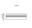
- FIG. 2 illustrates a laminated structure of a heater module for a heater according to a first exemplary embodiment of the present invention.
- a heater module 8 for a heater according to the first exemplary embodiment of the present invention includes an insulation substrate 101, a resistance pattern 103 laminated on one side or two sides of the insulation substrate 101, a first insulator layer 105 laminated on an upper surface of the resistance pattern 103, a conductor layer 107 laminated on an upper surface of the first insulator layer 105, and a protective layer 109 laminated on an upper surface of the conductor layer 107.
- the resistance pattern 103 laminated on one side or two sides of the insulation substrate 101 is formed to have a resistance value set by a length and a cross-sectional area, and operates as a heating element generating a heat quantity of the set resistance value when power is supplied.
- the resistance pattern 103 may be constituted by pure metals including copper, iron, nickel, chromium, and the like, or alloys which are mixtures of two or more metals at a predetermined ratio.
- the resistance patterns 103 are simultaneously formed on two parts of the insulation substrate 101 and electrically connected to each other by using a via hole, and as a result, a size of the insulation substrate 101 may be minimized and a heating amount may be maximally obtained.
- the first insulator layer 105 is coated on the upper surface of the resistance pattern 103 by a predetermined method to protect and insulate the resistance pattern 103, and may include colors such as green or white.
- the first insulator layer 105 is not coated but is exposed on a part of the ground constituted in the resistance pattern 103 by masking.
- the first insulator layer 105 may include colors such as green or white for distinguishing from the resistance pattern 103.
- the conductor layer 107 is coated on the upper surface of the first insulator layer 105 by a predetermined method so that the ground of the resistance pattern 103 exposed on the surface and the conductor layer 107 may naturally contact each other.
- the conductor layer 107 may be made of a metallic material including aluminum, copper, and the like, and may be deposited on the upper surface of the first insulator layer 105.
- the protective layer 109 is coated on the upper surface of the conductor layer 107 to stabilize the deposition of the conductor layer 107, provide an insulating property and electrical waterproofing, and provide excellent defense against chemical materials or oxidation.
- the protective layer 109 is constituted by harmless materials, and is formed as a thin film protective layer.
- the capacitance does not flow to the human body through the fluid or the blood infused to the patient and does not influence the signals measured by the apparatus for measuring the bio-electric signal, stable and reliable measurement of the bio-electric signal is provided.
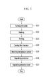
- FIG. 3 is a flowchart of a manufacturing process of the heater module for the heater according to the first exemplary embodiment of the present invention.
- the manufacturing process of the heater module for the heater according to the first exemplary embodiment of the present invention is performed as follows.
- a thin metal sheet is formed by coating pure metals including copper, iron, nickel, chromium, and the like or alloys which are mixtures of two or more metals at a predetermined ratio on the insulation substrate 101 by a predetermined method (S101).
- a mask for forming the resistance pattern 103 having a predetermined resistance value is mounted on the upper surface of the thin metal sheet (S102).
- a pattern 500 which sets a resistance value required for heating by a length and a cross-sectional area of a metal foil, and patterns such as a power supply terminal 510, a measuring terminal 530, an installation position 550 of a temperature sensor for measuring a temperature of the infused fluid or blood, and an exposed ground 570 are further included.
- an etching process is performed by coating a chemical material such as sulfuric acid on the upper portion of the mask for a predetermined time by a predetermined method and corroding other metal portions with a mask pattern (S103).
- the etching process may be performed by a method in which the thin metal sheet seated with the mask is soaked in the chemical material such as sulfuric acid for a predetermined time.
- step S103 When the etching process of step S103 is completed, the resistance pattern 103 having the predetermined resistance value is exposed by removing the mask and then washing with pure water, and the resistance pattern 103 is protected and electrically insulated from the outside by coating a first insulator on the upper surface of the resistance pattern 103 by the predetermined method (S104).
- the mask is applied so that the first insulator is not coated on the installation position 550 of the temperature sensor and the exposed ground 570.
- the temperature sensor is attached at the installation position 550 of the temperature sensor by soldering, and epoxy is coated on the upper portion thereof to be insulated (S105).
- the exposed ground 570 and the conductor may naturally electrically contact each other by depositing the conductor made of a metal material including aluminum, copper, and the like on the upper surface of the first insulator (S106).
- the thin film protective layer is deposited on the upper surface of the conductor with a harmless material to stabilize the deposition of the conductor and provide electrical insulation from the outside, waterproofing, and corrosion/chemical resistance (S107).
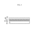
- FIG. 4 is a diagram illustrating a laminated structure of a heater module for a heater according to a second exemplary embodiment of the present invention.
- a heater module for a heater according to the second exemplary embodiment of the present invention an insulation substrate 101 and a resistance pattern 103 on one side or two sides of the insulation substrate 101 are laminated, a first insulator layer 105 is laminated on an upper surface of the resistance pattern 103, a conductor layer 107 is laminated on an upper surface of the first insulator layer 105, a second insulator layer 111 is laminated on an upper surface of the conductor layer 107, and a protective layer 109 is laminated on an upper surface of the second insulator layer 111.
- the resistance pattern 103 laminated on one side or two sides of the insulation substrate 101 is formed to have a resistance value set by a length and a cross-sectional area, and operates as a heating element generating a heat quantity of the set resistance value when power is supplied.
- the resistance pattern 103 may be constituted by pure metals including copper, iron, nickel, chromium, and the like, or alloys which are mixtures of two or more metals at a predetermined ratio.
- the resistance patterns 103 are simultaneously formed on the upper surface and the lower surface of the insulation substrate 101 and electrically connected to each other by using a via hole, and as a result, a size of the insulation substrate 101 may be minimized and a heating amount may be maximally obtained.
- the first insulator layer 105 is coated on the upper surface of the resistance pattern 103 by a predetermined method to protect and insulate the resistance pattern 103, and may include colors such as green or white.
- the first insulator layer 105 is not coated but is exposed on a part of the ground constituted in the resistance pattern 103 by masking.
- the conductor layer 107 is coated on the upper surface of the first insulator layer 105 by a predetermined method so that the exposed ground of the resistance pattern 103 and the conductor layer 107 may naturally contact each other.
- the conductor layer 107 may be made of a metallic material including aluminum, copper, and the like, and may be deposited on the upper surface of the first insulator layer 105.
- the second insulator layer 111 is coated on the upper surface of the conductor layer 107 by a predetermined method to stabilize the deposition of the conductor layer 107 and insulate the conductive layer 107 from the outside.
- the protective layer 109 is coated on the upper surface of the second insulator layer 111 to provide an insulating property from the outside and waterproofing and defense power against chemical materials or oxidation.
- the protective layer 109 is constituted by harmless materials, and is formed as a thin film protective layer.
- the capacitance does not flow to the human body through the fluid or the blood infused to the patient and does not influence the signals measured in the apparatus for measuring the bio-electric signal, the stable and reliable measurement of the bio-electric signal is provided.
- FIG. 5 is a flowchart of a manufacturing process of the heater module for the heater according to the second exemplary embodiment of the present invention.
- the manufacturing process of the heater module for the heater according to the second exemplary embodiment of the present invention is performed as follows.
- a thin metal sheet is formed by coating pure metals including copper, iron, nickel, chromium, and the like or alloys which are mixtures of two or more metals at a predetermined ratio on one side or two sides of the insulation substrate 101 by a predetermined method (S201).
- a mask for forming the resistance pattern 103 having a predetermined resistance value is mounted on the upper surface of the thin metal sheet (S202).
- a pattern 500 which sets a resistance value required for heating by a length and a cross-sectional area of a metal foil, and patterns such as a power supply terminal 510, a measuring terminal 530, an installation position 550 of a temperature sensor for measuring a temperature of the infused fluid or blood, and an exposed ground 570 are further included.
- an etching process is performed by coating a chemical material such as sulfuric acid on the upper portion of the mask for a predetermined time by a predetermined method and corroding other metal portions with a mask pattern (S203).
- the etching process may be performed by a method in which the thin metal sheet seated with the mask is soaked in the chemical material such as sulfuric acid for a predetermined time.
- the resistance pattern 103 having the predetermined resistance value is exposed by removing the mask and then washing with pure water, and the resistance pattern 103 is protected and electrically insulated from the outside by coating a first insulator on the upper surface of the resistance pattern 103 by the predetermined method (S204).
- the mask is applied so that the first insulator is not coated on the installation position 550 of the temperature sensor and the exposed ground 570.
- the temperature sensor is attached to the installation position 550 of the temperature sensor by soldering, and epoxy is coated on the upper portion thereof to be insulated (S205).
- the exposed ground 570 and the deposited conductor may naturally contact each other by depositing the conductor 107 made of a metal material including aluminum, copper, and the like on the upper surface of the first insulator (S206).
- a second insulator is coated on the upper surface of the conductor by a predetermined method to insulate the conductor from the outside (S207).
- the thin film protective layer (protective film) is deposited on the upper surface of the second insulator with a harmless material to provide electrical insulation from the outside, waterproofing, and corrosion/chemical resistance (S208).
- the heater modules for the heater having the laminated structures of the first exemplary embodiment and the second exemplary embodiment and the apparatus for measuring the bio-electric signal are simultaneously used, it is verified that the measured bio-electric signal is detected in a stable state without generating distortion of a waveform.
- the capacitance does not flow to the human body through the fluid or the blood infused to the patient and does not influence the signals measured in the apparatus for measuring the bio-electric signal, stable and reliable measurement of the bio-electric signal is provided.
Landscapes
- Engineering & Computer Science (AREA)
- Health & Medical Sciences (AREA)
- Public Health (AREA)
- Veterinary Medicine (AREA)
- Biomedical Technology (AREA)
- Heart & Thoracic Surgery (AREA)
- General Engineering & Computer Science (AREA)
- Life Sciences & Earth Sciences (AREA)
- Animal Behavior & Ethology (AREA)
- General Health & Medical Sciences (AREA)
- Vascular Medicine (AREA)
- Mechanical Engineering (AREA)
- Physics & Mathematics (AREA)
- Thermal Sciences (AREA)
- Chemical & Material Sciences (AREA)
- Combustion & Propulsion (AREA)
- Anesthesiology (AREA)
- Hematology (AREA)
- Infusion, Injection, And Reservoir Apparatuses (AREA)
- Resistance Heating (AREA)
- Surface Heating Bodies (AREA)
Priority Applications (1)
| Application Number | Priority Date | Filing Date | Title |
|---|---|---|---|
| PL13875789T PL2959932T3 (pl) | 2013-02-22 | 2013-02-22 | Moduł grzewczy podgrzewacza w aparacie do infuzji płynów i sposób jego wykonania |
Applications Claiming Priority (1)
| Application Number | Priority Date | Filing Date | Title |
|---|---|---|---|
| PCT/KR2013/001422 WO2014129687A1 (ko) | 2013-02-22 | 2013-02-22 | 수액주입장치의 가온기용 히터모듈 및 그것의 제조방법 |
Publications (3)
| Publication Number | Publication Date |
|---|---|
| EP2959932A1 true EP2959932A1 (de) | 2015-12-30 |
| EP2959932A4 EP2959932A4 (de) | 2017-05-03 |
| EP2959932B1 EP2959932B1 (de) | 2019-01-09 |
Family
ID=51391459
Family Applications (1)
| Application Number | Title | Priority Date | Filing Date |
|---|---|---|---|
| EP13875789.3A Not-in-force EP2959932B1 (de) | 2013-02-22 | 2013-02-22 | Heizmodul für ein heizaggregat einer flüssigkeitsinfusionsvorrichtung und verfahren zu dessen herstellung |
Country Status (10)
| Country | Link |
|---|---|
| US (1) | US9730273B2 (de) |
| EP (1) | EP2959932B1 (de) |
| JP (1) | JP6158291B2 (de) |
| CN (1) | CN104220119B (de) |
| AU (1) | AU2013378951A1 (de) |
| CA (1) | CA2867075C (de) |
| ES (1) | ES2711829T3 (de) |
| PL (1) | PL2959932T3 (de) |
| RU (1) | RU2586970C1 (de) |
| WO (1) | WO2014129687A1 (de) |
Cited By (1)
| Publication number | Priority date | Publication date | Assignee | Title |
|---|---|---|---|---|
| WO2021058505A1 (de) * | 2019-09-24 | 2021-04-01 | Vitesco Technologies GmbH | Elektrische heizvorrichtung für ein fahrzeug, sowie verfahren zur herstellung und verwendung eines ätzverfahrens |
Families Citing this family (4)
| Publication number | Priority date | Publication date | Assignee | Title |
|---|---|---|---|---|
| US10052441B2 (en) * | 2016-08-02 | 2018-08-21 | Becton, Dickinson And Company | System and method for measuring delivered dose |
| RU170115U1 (ru) * | 2016-08-25 | 2017-04-14 | Межрегиональное общественное учреждение "Институт инженерной физики" | Капельница медицинская |
| US10669033B2 (en) * | 2017-12-21 | 2020-06-02 | The Boeing Company | Integrated lightning protection and electrical de-icing for aerodynamic structures |
| WO2024034905A1 (ko) * | 2022-08-12 | 2024-02-15 | 주식회사 경동나비엔 | 열교환기 및 이를 구비한 물 가열 장치 |
Family Cites Families (25)
| Publication number | Priority date | Publication date | Assignee | Title |
|---|---|---|---|---|
| US3694627A (en) * | 1970-12-23 | 1972-09-26 | Whirlpool Co | Heating element & method of making |
| JPH0634473B2 (ja) * | 1988-07-23 | 1994-05-02 | 堺電子工業株式会社 | 電磁波遮蔽付フレキシブルプリント回路形成体 |
| US5245693A (en) * | 1991-03-15 | 1993-09-14 | In-Touch Products Co. | Parenteral fluid warmer apparatus and disposable cassette utilizing thin, flexible heat-exchange membrane |
| US5381510A (en) * | 1991-03-15 | 1995-01-10 | In-Touch Products Co. | In-line fluid heating apparatus with gradation of heat energy from inlet to outlet |
| US5448037A (en) * | 1992-08-03 | 1995-09-05 | Mitsui Toatsu Chemicals, Inc. | Transparent panel heater and method for manufacturing same |
| JPH07192849A (ja) | 1993-12-27 | 1995-07-28 | Mitsui Toatsu Chem Inc | 透明面状ヒーターの製造方法 |
| JPH10134944A (ja) * | 1996-10-25 | 1998-05-22 | Sharp Corp | 面状電気採暖具 |
| JPH11121908A (ja) * | 1997-10-08 | 1999-04-30 | Sumitomo Electric Ind Ltd | プリント配線板とその製造方法 |
| JP2000150119A (ja) * | 1998-11-04 | 2000-05-30 | Komatsu Ltd | 薄膜ヒータ及びその製造方法 |
| EP1066844B1 (de) * | 1999-07-06 | 2005-10-05 | Smiths Medical ASD, Inc. | Intravenöse Flüssigkeitsheizvorrichtung zum Erwärmen der Flüssigkeit im Infusionsschlauch |
| US6336003B1 (en) * | 2000-09-01 | 2002-01-01 | Automatic Medical Technologies, Inc. | Max one I.V. warmer |
| JP4480918B2 (ja) | 2001-06-01 | 2010-06-16 | 株式会社美鈴工業 | 通電遮断機能付きヒーター |
| US6608968B2 (en) | 2001-11-23 | 2003-08-19 | Allan P Bakke | Convection blood warming system with disposable flattened tube envelope incorporating paperboard “needle” for inserting envelope between heating plates and employing active and passive insulation of outlet flow path to provide normothermic fluid at zero to 600 milliliters per minute |
| JP2004215758A (ja) * | 2003-01-10 | 2004-08-05 | Futaba Corp | 液体の加温用容器及び加温器 |
| JP4528298B2 (ja) | 2003-07-09 | 2010-08-18 | エンジニビティー リミテッド ライアビリティ カンパニー | 医療用流体の加温システム |
| KR100577406B1 (ko) | 2003-09-17 | 2006-05-10 | 박재상 | Pcb 방식을 이용한 히터 제조방법 및 히터 |
| KR100553129B1 (ko) * | 2003-09-17 | 2006-02-20 | 박재상 | Pcb 방식으로 제작된 히터를 갖는 가온장치 |
| US20050148934A1 (en) | 2003-12-24 | 2005-07-07 | Mallinckrodt Inc. | Fluid infusion apparatus with an insulated patient line tubing for preventing heat loss |
| CN2855437Y (zh) * | 2005-11-04 | 2007-01-10 | 朱荣荣 | 干式输液加温器 |
| WO2007114143A1 (ja) * | 2006-03-28 | 2007-10-11 | Mitsui Mining & Smelting Co., Ltd. | 薄膜センサの製造方法、薄膜センサおよび薄膜センサモジュール |
| JP2007294929A (ja) * | 2006-03-28 | 2007-11-08 | Mitsui Mining & Smelting Co Ltd | 薄膜センサの製造方法、薄膜センサおよび薄膜センサモジュール |
| US7846130B2 (en) * | 2007-03-13 | 2010-12-07 | Quality In Flow Ltd. | Portable intravenous fluid heating system |
| WO2010134893A1 (en) * | 2009-05-22 | 2010-11-25 | Agency For Science, Technology And Research | A flexible fluid storage and warming bag and a fluid storage and warming system |
| EP2547386A2 (de) | 2010-03-16 | 2013-01-23 | Barkey GmbH & Co. KG | Vorrichtung zum erwärmen von strömenden fluiden sowie herstellungsverfahren |
| KR100980757B1 (ko) | 2010-03-23 | 2010-09-10 | 주식회사 무한기업 | 의료용 가온기 |
-
2013
- 2013-02-22 EP EP13875789.3A patent/EP2959932B1/de not_active Not-in-force
- 2013-02-22 US US14/382,570 patent/US9730273B2/en not_active Expired - Fee Related
- 2013-02-22 WO PCT/KR2013/001422 patent/WO2014129687A1/ko not_active Ceased
- 2013-02-22 PL PL13875789T patent/PL2959932T3/pl unknown
- 2013-02-22 RU RU2014136450/14A patent/RU2586970C1/ru active
- 2013-02-22 ES ES13875789T patent/ES2711829T3/es active Active
- 2013-02-22 CA CA2867075A patent/CA2867075C/en not_active Expired - Fee Related
- 2013-02-22 JP JP2015501564A patent/JP6158291B2/ja not_active Expired - Fee Related
- 2013-02-22 CN CN201380019334.7A patent/CN104220119B/zh not_active Expired - Fee Related
- 2013-02-22 AU AU2013378951A patent/AU2013378951A1/en not_active Abandoned
Cited By (1)
| Publication number | Priority date | Publication date | Assignee | Title |
|---|---|---|---|---|
| WO2021058505A1 (de) * | 2019-09-24 | 2021-04-01 | Vitesco Technologies GmbH | Elektrische heizvorrichtung für ein fahrzeug, sowie verfahren zur herstellung und verwendung eines ätzverfahrens |
Also Published As
| Publication number | Publication date |
|---|---|
| CN104220119B (zh) | 2017-04-12 |
| CA2867075C (en) | 2016-09-20 |
| ES2711829T3 (es) | 2019-05-07 |
| JP2015510439A (ja) | 2015-04-09 |
| RU2586970C1 (ru) | 2016-06-10 |
| AU2013378951A1 (en) | 2014-09-25 |
| EP2959932B1 (de) | 2019-01-09 |
| US9730273B2 (en) | 2017-08-08 |
| WO2014129687A1 (ko) | 2014-08-28 |
| JP6158291B2 (ja) | 2017-07-05 |
| EP2959932A4 (de) | 2017-05-03 |
| US20150359041A1 (en) | 2015-12-10 |
| PL2959932T3 (pl) | 2019-06-28 |
| CA2867075A1 (en) | 2014-08-28 |
| CN104220119A (zh) | 2014-12-17 |
Similar Documents
| Publication | Publication Date | Title |
|---|---|---|
| US9730273B2 (en) | Heater module for heater of fluid infusion apparatus and manufacturing method thereof | |
| US8126530B2 (en) | Offset electrode | |
| JP6003928B2 (ja) | ガスセンサ素子とその製造方法並びにガスセンサ | |
| US20200076016A1 (en) | Sensored Battery Pouch | |
| JP2021526069A5 (de) | ||
| US11268864B2 (en) | Sensor unit for detecting a spatial temperature profile and method for producing a sensor unit | |
| US11911094B2 (en) | Heat transfer through a catheter tip | |
| KR20150034128A (ko) | 저 저항 전류 측정용 저항기 | |
| CN107915200A (zh) | 微传感器封装 | |
| EP3610814B1 (de) | Verbesserte wärmeübertragung während ablationsverfahren | |
| JP2008286810A (ja) | 酸素センサ素子 | |
| KR101281798B1 (ko) | 가온기용 히터모듈 및 그것의 제조방법 | |
| EP3766447B1 (de) | Verbesserte wärmeübertragung durch eine katheterspitze | |
| RU2537754C1 (ru) | Способ изготовления датчиков температуры и теплового потока (варианты) | |
| KR20210031685A (ko) | 절연층 형성 방법, 절연층을 가지는 부재, 저항 측정 방법 및 접합형 정류 소자 | |
| US12007346B2 (en) | Electrical insulation in garments | |
| CN103245707A (zh) | 用于电化学测量系统中的应用的电极 | |
| US20120118752A1 (en) | Method for Electrodeposition of an Electrode on a Dielectric Substrate | |
| EP4351706B1 (de) | Medizinische elektrode und anordnung davon | |
| JP6678415B2 (ja) | 接触燃焼式ガスセンサ及びその製造方法 | |
| RU220876U1 (ru) | Комбинированный электрод экг-температура | |
| EP3503128B1 (de) | Vorrichtung, system und verfahren für elektrische verbindung | |
| EP3155993B1 (de) | Elektrokatheter mit einer einen metallkörper und eine kunststoffbeschichtung umfassenden elektrode | |
| AT502636A2 (de) | Verfahren zur herstellung eines temperatursensors | |
| JP2007024908A (ja) | ガス濃度検出装置 |
Legal Events
| Date | Code | Title | Description |
|---|---|---|---|
| PUAI | Public reference made under article 153(3) epc to a published international application that has entered the european phase |
Free format text: ORIGINAL CODE: 0009012 |
|
| 17P | Request for examination filed |
Effective date: 20140908 |
|
| AK | Designated contracting states |
Kind code of ref document: A1 Designated state(s): AL AT BE BG CH CY CZ DE DK EE ES FI FR GB GR HR HU IE IS IT LI LT LU LV MC MK MT NL NO PL PT RO RS SE SI SK SM TR |
|
| AX | Request for extension of the european patent |
Extension state: BA ME |
|
| DAX | Request for extension of the european patent (deleted) | ||
| A4 | Supplementary search report drawn up and despatched |
Effective date: 20170404 |
|
| RIC1 | Information provided on ipc code assigned before grant |
Ipc: H05B 3/26 20060101ALI20170329BHEP Ipc: H05B 3/06 20060101ALI20170329BHEP Ipc: H05B 3/22 20060101ALI20170329BHEP Ipc: A61F 7/12 20060101ALI20170329BHEP Ipc: A61F 7/00 20060101ALI20170329BHEP Ipc: H05B 3/28 20060101ALI20170329BHEP Ipc: H05B 3/00 20060101ALI20170329BHEP Ipc: A61M 1/36 20060101ALI20170329BHEP Ipc: F24H 1/14 20060101ALI20170329BHEP Ipc: A61M 5/44 20060101AFI20170329BHEP Ipc: H05B 3/04 20060101ALI20170329BHEP Ipc: F24H 1/12 20060101ALI20170329BHEP Ipc: F24H 9/20 20060101ALI20170329BHEP |
|
| RIC1 | Information provided on ipc code assigned before grant |
Ipc: H05B 3/26 20060101ALI20180427BHEP Ipc: F24H 1/14 20060101ALI20180427BHEP Ipc: A61F 7/00 20060101ALI20180427BHEP Ipc: H05B 3/04 20060101ALI20180427BHEP Ipc: F24H 9/20 20060101ALI20180427BHEP Ipc: A61F 7/12 20060101ALI20180427BHEP Ipc: H05B 3/00 20060101ALI20180427BHEP Ipc: H05B 3/28 20060101ALI20180427BHEP Ipc: A61M 5/44 20060101AFI20180427BHEP Ipc: F24H 1/12 20060101ALI20180427BHEP Ipc: H05B 3/06 20060101ALI20180427BHEP Ipc: H05B 3/22 20060101ALI20180427BHEP Ipc: A61M 1/36 20060101ALI20180427BHEP |
|
| GRAP | Despatch of communication of intention to grant a patent |
Free format text: ORIGINAL CODE: EPIDOSNIGR1 |
|
| STAA | Information on the status of an ep patent application or granted ep patent |
Free format text: STATUS: GRANT OF PATENT IS INTENDED |
|
| INTG | Intention to grant announced |
Effective date: 20180718 |
|
| GRAS | Grant fee paid |
Free format text: ORIGINAL CODE: EPIDOSNIGR3 |
|
| GRAA | (expected) grant |
Free format text: ORIGINAL CODE: 0009210 |
|
| STAA | Information on the status of an ep patent application or granted ep patent |
Free format text: STATUS: THE PATENT HAS BEEN GRANTED |
|
| AK | Designated contracting states |
Kind code of ref document: B1 Designated state(s): AL AT BE BG CH CY CZ DE DK EE ES FI FR GB GR HR HU IE IS IT LI LT LU LV MC MK MT NL NO PL PT RO RS SE SI SK SM TR |
|
| REG | Reference to a national code |
Ref country code: GB Ref legal event code: FG4D |
|
| REG | Reference to a national code |
Ref country code: AT Ref legal event code: REF Ref document number: 1086543 Country of ref document: AT Kind code of ref document: T Effective date: 20190115 Ref country code: CH Ref legal event code: EP |
|
| REG | Reference to a national code |
Ref country code: DE Ref legal event code: R096 Ref document number: 602013049740 Country of ref document: DE |
|
| REG | Reference to a national code |
Ref country code: IE Ref legal event code: FG4D |
|
| REG | Reference to a national code |
Ref country code: CH Ref legal event code: NV Representative=s name: GEVERS SA, CH |
|
| REG | Reference to a national code |
Ref country code: SE Ref legal event code: TRGR |
|
| REG | Reference to a national code |
Ref country code: NL Ref legal event code: FP |
|
| REG | Reference to a national code |
Ref country code: ES Ref legal event code: FG2A Ref document number: 2711829 Country of ref document: ES Kind code of ref document: T3 Effective date: 20190507 |
|
| REG | Reference to a national code |
Ref country code: LT Ref legal event code: MG4D |
|
| REG | Reference to a national code |
Ref country code: AT Ref legal event code: MK05 Ref document number: 1086543 Country of ref document: AT Kind code of ref document: T Effective date: 20190109 |
|
| PG25 | Lapsed in a contracting state [announced via postgrant information from national office to epo] |
Ref country code: FI Free format text: LAPSE BECAUSE OF FAILURE TO SUBMIT A TRANSLATION OF THE DESCRIPTION OR TO PAY THE FEE WITHIN THE PRESCRIBED TIME-LIMIT Effective date: 20190109 Ref country code: LT Free format text: LAPSE BECAUSE OF FAILURE TO SUBMIT A TRANSLATION OF THE DESCRIPTION OR TO PAY THE FEE WITHIN THE PRESCRIBED TIME-LIMIT Effective date: 20190109 Ref country code: NO Free format text: LAPSE BECAUSE OF FAILURE TO SUBMIT A TRANSLATION OF THE DESCRIPTION OR TO PAY THE FEE WITHIN THE PRESCRIBED TIME-LIMIT Effective date: 20190409 Ref country code: PT Free format text: LAPSE BECAUSE OF FAILURE TO SUBMIT A TRANSLATION OF THE DESCRIPTION OR TO PAY THE FEE WITHIN THE PRESCRIBED TIME-LIMIT Effective date: 20190509 |
|
| PG25 | Lapsed in a contracting state [announced via postgrant information from national office to epo] |
Ref country code: HR Free format text: LAPSE BECAUSE OF FAILURE TO SUBMIT A TRANSLATION OF THE DESCRIPTION OR TO PAY THE FEE WITHIN THE PRESCRIBED TIME-LIMIT Effective date: 20190109 Ref country code: LV Free format text: LAPSE BECAUSE OF FAILURE TO SUBMIT A TRANSLATION OF THE DESCRIPTION OR TO PAY THE FEE WITHIN THE PRESCRIBED TIME-LIMIT Effective date: 20190109 Ref country code: IS Free format text: LAPSE BECAUSE OF FAILURE TO SUBMIT A TRANSLATION OF THE DESCRIPTION OR TO PAY THE FEE WITHIN THE PRESCRIBED TIME-LIMIT Effective date: 20190509 Ref country code: GR Free format text: LAPSE BECAUSE OF FAILURE TO SUBMIT A TRANSLATION OF THE DESCRIPTION OR TO PAY THE FEE WITHIN THE PRESCRIBED TIME-LIMIT Effective date: 20190410 Ref country code: RS Free format text: LAPSE BECAUSE OF FAILURE TO SUBMIT A TRANSLATION OF THE DESCRIPTION OR TO PAY THE FEE WITHIN THE PRESCRIBED TIME-LIMIT Effective date: 20190109 Ref country code: BG Free format text: LAPSE BECAUSE OF FAILURE TO SUBMIT A TRANSLATION OF THE DESCRIPTION OR TO PAY THE FEE WITHIN THE PRESCRIBED TIME-LIMIT Effective date: 20190409 |
|
| REG | Reference to a national code |
Ref country code: DE Ref legal event code: R097 Ref document number: 602013049740 Country of ref document: DE |
|
| PG25 | Lapsed in a contracting state [announced via postgrant information from national office to epo] |
Ref country code: CZ Free format text: LAPSE BECAUSE OF FAILURE TO SUBMIT A TRANSLATION OF THE DESCRIPTION OR TO PAY THE FEE WITHIN THE PRESCRIBED TIME-LIMIT Effective date: 20190109 Ref country code: RO Free format text: LAPSE BECAUSE OF FAILURE TO SUBMIT A TRANSLATION OF THE DESCRIPTION OR TO PAY THE FEE WITHIN THE PRESCRIBED TIME-LIMIT Effective date: 20190109 Ref country code: EE Free format text: LAPSE BECAUSE OF FAILURE TO SUBMIT A TRANSLATION OF THE DESCRIPTION OR TO PAY THE FEE WITHIN THE PRESCRIBED TIME-LIMIT Effective date: 20190109 Ref country code: AT Free format text: LAPSE BECAUSE OF FAILURE TO SUBMIT A TRANSLATION OF THE DESCRIPTION OR TO PAY THE FEE WITHIN THE PRESCRIBED TIME-LIMIT Effective date: 20190109 Ref country code: DK Free format text: LAPSE BECAUSE OF FAILURE TO SUBMIT A TRANSLATION OF THE DESCRIPTION OR TO PAY THE FEE WITHIN THE PRESCRIBED TIME-LIMIT Effective date: 20190109 Ref country code: MC Free format text: LAPSE BECAUSE OF FAILURE TO SUBMIT A TRANSLATION OF THE DESCRIPTION OR TO PAY THE FEE WITHIN THE PRESCRIBED TIME-LIMIT Effective date: 20190109 Ref country code: LU Free format text: LAPSE BECAUSE OF NON-PAYMENT OF DUE FEES Effective date: 20190222 Ref country code: AL Free format text: LAPSE BECAUSE OF FAILURE TO SUBMIT A TRANSLATION OF THE DESCRIPTION OR TO PAY THE FEE WITHIN THE PRESCRIBED TIME-LIMIT Effective date: 20190109 Ref country code: SK Free format text: LAPSE BECAUSE OF FAILURE TO SUBMIT A TRANSLATION OF THE DESCRIPTION OR TO PAY THE FEE WITHIN THE PRESCRIBED TIME-LIMIT Effective date: 20190109 |
|
| PLBE | No opposition filed within time limit |
Free format text: ORIGINAL CODE: 0009261 |
|
| STAA | Information on the status of an ep patent application or granted ep patent |
Free format text: STATUS: NO OPPOSITION FILED WITHIN TIME LIMIT |
|
| REG | Reference to a national code |
Ref country code: BE Ref legal event code: MM Effective date: 20190228 |
|
| REG | Reference to a national code |
Ref country code: IE Ref legal event code: MM4A |
|
| PG25 | Lapsed in a contracting state [announced via postgrant information from national office to epo] |
Ref country code: SM Free format text: LAPSE BECAUSE OF FAILURE TO SUBMIT A TRANSLATION OF THE DESCRIPTION OR TO PAY THE FEE WITHIN THE PRESCRIBED TIME-LIMIT Effective date: 20190109 |
|
| 26N | No opposition filed |
Effective date: 20191010 |
|
| PG25 | Lapsed in a contracting state [announced via postgrant information from national office to epo] |
Ref country code: IE Free format text: LAPSE BECAUSE OF NON-PAYMENT OF DUE FEES Effective date: 20190222 |
|
| PG25 | Lapsed in a contracting state [announced via postgrant information from national office to epo] |
Ref country code: SI Free format text: LAPSE BECAUSE OF FAILURE TO SUBMIT A TRANSLATION OF THE DESCRIPTION OR TO PAY THE FEE WITHIN THE PRESCRIBED TIME-LIMIT Effective date: 20190109 Ref country code: BE Free format text: LAPSE BECAUSE OF NON-PAYMENT OF DUE FEES Effective date: 20190228 |
|
| PG25 | Lapsed in a contracting state [announced via postgrant information from national office to epo] |
Ref country code: TR Free format text: LAPSE BECAUSE OF FAILURE TO SUBMIT A TRANSLATION OF THE DESCRIPTION OR TO PAY THE FEE WITHIN THE PRESCRIBED TIME-LIMIT Effective date: 20190109 |
|
| PGFP | Annual fee paid to national office [announced via postgrant information from national office to epo] |
Ref country code: NL Payment date: 20200212 Year of fee payment: 8 Ref country code: SE Payment date: 20200210 Year of fee payment: 8 Ref country code: ES Payment date: 20200302 Year of fee payment: 8 Ref country code: GB Payment date: 20200212 Year of fee payment: 8 Ref country code: IT Payment date: 20200221 Year of fee payment: 8 Ref country code: DE Payment date: 20200211 Year of fee payment: 8 Ref country code: PL Payment date: 20200207 Year of fee payment: 8 |
|
| PGFP | Annual fee paid to national office [announced via postgrant information from national office to epo] |
Ref country code: CH Payment date: 20200213 Year of fee payment: 8 |
|
| PG25 | Lapsed in a contracting state [announced via postgrant information from national office to epo] |
Ref country code: MT Free format text: LAPSE BECAUSE OF NON-PAYMENT OF DUE FEES Effective date: 20190222 |
|
| PGFP | Annual fee paid to national office [announced via postgrant information from national office to epo] |
Ref country code: FR Payment date: 20200214 Year of fee payment: 8 |
|
| PG25 | Lapsed in a contracting state [announced via postgrant information from national office to epo] |
Ref country code: CY Free format text: LAPSE BECAUSE OF FAILURE TO SUBMIT A TRANSLATION OF THE DESCRIPTION OR TO PAY THE FEE WITHIN THE PRESCRIBED TIME-LIMIT Effective date: 20190109 |
|
| PG25 | Lapsed in a contracting state [announced via postgrant information from national office to epo] |
Ref country code: HU Free format text: LAPSE BECAUSE OF FAILURE TO SUBMIT A TRANSLATION OF THE DESCRIPTION OR TO PAY THE FEE WITHIN THE PRESCRIBED TIME-LIMIT; INVALID AB INITIO Effective date: 20130222 |
|
| REG | Reference to a national code |
Ref country code: DE Ref legal event code: R119 Ref document number: 602013049740 Country of ref document: DE |
|
| REG | Reference to a national code |
Ref country code: SE Ref legal event code: EUG |
|
| GBPC | Gb: european patent ceased through non-payment of renewal fee |
Effective date: 20210222 |
|
| PG25 | Lapsed in a contracting state [announced via postgrant information from national office to epo] |
Ref country code: LI Free format text: LAPSE BECAUSE OF NON-PAYMENT OF DUE FEES Effective date: 20210228 Ref country code: CH Free format text: LAPSE BECAUSE OF NON-PAYMENT OF DUE FEES Effective date: 20210228 |
|
| PG25 | Lapsed in a contracting state [announced via postgrant information from national office to epo] |
Ref country code: SE Free format text: LAPSE BECAUSE OF NON-PAYMENT OF DUE FEES Effective date: 20210223 |
|
| REG | Reference to a national code |
Ref country code: NL Ref legal event code: MM Effective date: 20210301 |
|
| PG25 | Lapsed in a contracting state [announced via postgrant information from national office to epo] |
Ref country code: NL Free format text: LAPSE BECAUSE OF NON-PAYMENT OF DUE FEES Effective date: 20210301 |
|
| PG25 | Lapsed in a contracting state [announced via postgrant information from national office to epo] |
Ref country code: DE Free format text: LAPSE BECAUSE OF NON-PAYMENT OF DUE FEES Effective date: 20210901 Ref country code: FR Free format text: LAPSE BECAUSE OF NON-PAYMENT OF DUE FEES Effective date: 20210228 Ref country code: GB Free format text: LAPSE BECAUSE OF NON-PAYMENT OF DUE FEES Effective date: 20210222 |
|
| PG25 | Lapsed in a contracting state [announced via postgrant information from national office to epo] |
Ref country code: IT Free format text: LAPSE BECAUSE OF NON-PAYMENT OF DUE FEES Effective date: 20210222 |
|
| REG | Reference to a national code |
Ref country code: ES Ref legal event code: FD2A Effective date: 20220523 |
|
| PG25 | Lapsed in a contracting state [announced via postgrant information from national office to epo] |
Ref country code: MK Free format text: LAPSE BECAUSE OF FAILURE TO SUBMIT A TRANSLATION OF THE DESCRIPTION OR TO PAY THE FEE WITHIN THE PRESCRIBED TIME-LIMIT Effective date: 20190109 |
|
| PG25 | Lapsed in a contracting state [announced via postgrant information from national office to epo] |
Ref country code: ES Free format text: LAPSE BECAUSE OF NON-PAYMENT OF DUE FEES Effective date: 20210223 |
|
| PG25 | Lapsed in a contracting state [announced via postgrant information from national office to epo] |
Ref country code: PL Free format text: LAPSE BECAUSE OF NON-PAYMENT OF DUE FEES Effective date: 20210222 |