EP2960396A1 - Dispositif de fixation d'un profile de visualisation - Google Patents
Dispositif de fixation d'un profile de visualisation Download PDFInfo
- Publication number
- EP2960396A1 EP2960396A1 EP15174170.9A EP15174170A EP2960396A1 EP 2960396 A1 EP2960396 A1 EP 2960396A1 EP 15174170 A EP15174170 A EP 15174170A EP 2960396 A1 EP2960396 A1 EP 2960396A1
- Authority
- EP
- European Patent Office
- Prior art keywords
- profile
- longitudinal groove
- holding part
- web
- sight
- Prior art date
- Legal status (The legal status is an assumption and is not a legal conclusion. Google has not performed a legal analysis and makes no representation as to the accuracy of the status listed.)
- Withdrawn
Links
- 239000000758 substrate Substances 0.000 claims abstract description 9
- IHQKEDIOMGYHEB-UHFFFAOYSA-M sodium dimethylarsinate Chemical class [Na+].C[As](C)([O-])=O IHQKEDIOMGYHEB-UHFFFAOYSA-M 0.000 claims description 3
- 230000000007 visual effect Effects 0.000 description 9
- 230000008961 swelling Effects 0.000 description 6
- 238000004873 anchoring Methods 0.000 description 4
- 239000000463 material Substances 0.000 description 3
- 239000002023 wood Substances 0.000 description 2
- 230000006978 adaptation Effects 0.000 description 1
- 230000000694 effects Effects 0.000 description 1
- 238000003780 insertion Methods 0.000 description 1
- 230000037431 insertion Effects 0.000 description 1
- 238000009434 installation Methods 0.000 description 1
- 230000001788 irregular Effects 0.000 description 1
- 238000004519 manufacturing process Methods 0.000 description 1
Images


Classifications
-
- E—FIXED CONSTRUCTIONS
- E04—BUILDING
- E04F—FINISHING WORK ON BUILDINGS, e.g. STAIRS, FLOORS
- E04F15/00—Flooring
- E04F15/02—Flooring or floor layers composed of a number of similar elements
- E04F15/02044—Separate elements for fastening to an underlayer
-
- E—FIXED CONSTRUCTIONS
- E04—BUILDING
- E04F—FINISHING WORK ON BUILDINGS, e.g. STAIRS, FLOORS
- E04F15/00—Flooring
- E04F15/02—Flooring or floor layers composed of a number of similar elements
- E04F15/02177—Floor elements for use at a specific location
- E04F15/02183—Floor elements for use at a specific location for outdoor use, e.g. in decks, patios, terraces, verandas or the like
-
- E—FIXED CONSTRUCTIONS
- E04—BUILDING
- E04F—FINISHING WORK ON BUILDINGS, e.g. STAIRS, FLOORS
- E04F15/00—Flooring
- E04F15/02—Flooring or floor layers composed of a number of similar elements
- E04F15/02044—Separate elements for fastening to an underlayer
- E04F2015/0205—Separate elements for fastening to an underlayer with load-supporting elongated furring elements between the flooring elements and the underlayer
- E04F2015/02066—Separate elements for fastening to an underlayer with load-supporting elongated furring elements between the flooring elements and the underlayer with additional fastening elements between furring elements and flooring elements
- E04F2015/02072—Separate elements for fastening to an underlayer with load-supporting elongated furring elements between the flooring elements and the underlayer with additional fastening elements between furring elements and flooring elements the additional fastening elements extending into the back side of the flooring elements
-
- E—FIXED CONSTRUCTIONS
- E04—BUILDING
- E04F—FINISHING WORK ON BUILDINGS, e.g. STAIRS, FLOORS
- E04F15/00—Flooring
- E04F15/02—Flooring or floor layers composed of a number of similar elements
- E04F15/02044—Separate elements for fastening to an underlayer
- E04F2015/0205—Separate elements for fastening to an underlayer with load-supporting elongated furring elements between the flooring elements and the underlayer
- E04F2015/02066—Separate elements for fastening to an underlayer with load-supporting elongated furring elements between the flooring elements and the underlayer with additional fastening elements between furring elements and flooring elements
- E04F2015/02077—Separate elements for fastening to an underlayer with load-supporting elongated furring elements between the flooring elements and the underlayer with additional fastening elements between furring elements and flooring elements the additional fastening elements located in-between two adjacent flooring elements
- E04F2015/02094—Engaging side grooves running along the whole length of the flooring elements
Definitions
- the invention relates to a device for attaching at least one sight profile, in particular terrace profile, to a substrate, with at least one anchor profile attachable to the ground and with at least two holding parts connected to the anchor profile, each with their webs both in a bottom groove of the sight profile and in a longitudinal groove of the sight profile for holding the sight profile on the anchor profile are formed engageable.
- the DE 202013102695U1 shows visible profiles for a terrace covering. These are fastened with holding parts to an underlying anchor profile.
- the anchor profile can be designed, for example, as a padding applied to the substrate.
- the holding part is fixed with screws.
- the holding part In order to hold the viewing profiles on the anchor element, the holding part webs, which engage in both a bottom groove and in a longitudinal groove of the sight profile for holding the sight profile.
- This device is only conditionally suitable for laying for wooden floors, the material due to shrinkage and swelling.
- the DE 102008048560A1 shows holding parts for viewing profiles on an anchor profile, which are designed as carrier boards.
- the holding parts consist of rectangular plates, which are connected to the sight profiles via a screw or clip connection.
- One of the two holding parts is screwed to the anchor element, while the other is only placed on top to allow the shrinkage or swelling of the floor boards. Nevertheless, in such a form of assembly - especially after several cycles of swelling and shrinking - form a floor with irregular columns and sometimes even with dislocations.
- the invention is therefore based on the object, starting from the above-described prior art, to improve a device to the effect that the viewing profiles can be easily attached to the ground.
- the device should still have high stability.
- the rail-shaped armature profile has at least one upwardly open and undercut longitudinal groove and the holding parts in each case have engageable in their associated longitudinal groove guide elements.
- the viewing profiles can first be easily attached to the ground - among other things, since the upwardly open longitudinal groove inserting the guide elements can facilitate. Since the longitudinal groove is undercut, may also open the option that the guide elements used - for example by their rotation - projections etc. of the anchor profile engage behind to prevent unwanted detachment of the holding parts. Furthermore, the viewing profiles can be easily aligned and positioned over engaging in the longitudinal groove guide elements. The advantages can be further improved if such guide elements are also designed to be displaceable in the longitudinal groove.
- a significant advantage of the device according to the invention also results from, by means of engaging and displaceable in a longitudinal guide elements size changes of the sight profiles in the transverse direction, as they occur for example by swelling and shrinkage in wood, are compensated.
- the device can thus be kept free from mechanical stresses, whereby a high stability can be guaranteed.
- first holding part has a first guide element which can be freely removed upwardly from the respective longitudinal groove and the other second holding part has a second guide element engaging behind its respective longitudinal groove.
- first guide element which can be freely removed upwardly from the respective longitudinal groove
- second holding part has a second guide element engaging behind its respective longitudinal groove.
- the free upwardly removable first guide element also facilitate the alignment of the visual profiles - such as this can be used in a simple manner in the respective longitudinal groove.
- the insertion of the holding parts in the respective longitudinal groove and thus the assembly of the visual profiles can be further simplified if the, its respective longitudinal groove engages behind the second guide element rotatably formed in this longitudinal groove and freely removable in at least one rotational position of its respective longitudinal groove upwards.
- the second holding part which is fastened, for example, to the viewing profile, can in fact be introduced into the longitudinal groove in the first step and then secured by twisting the visual profile together with its second holding part in the longitudinal groove against accidental removal from the longitudinal groove.
- a stable guidance of the visual profiles in their alignment or fastening can be created.
- the position of the sight profile can be fixed with the aid of the first holding part.
- a thread-cutting screw can prove itself for this purpose.
- the second holding part by its relative to the first holding member slidable storage in the longitudinal groove allow compensation for any size changes of the sight profiles in their transverse direction.
- the visual profiles can be fixed steadfast - with an adaptation of this attachment to material-related changes in the visual profiles in size is possible.
- the device can permit a simple and secure mounting of the viewing profiles.
- connection means projects through the first guide element of the first holding part. Since the first holding part protrudes into the anchor element in the region of the guide element, anchoring by the guide element can be characterized by high stability.
- a, in particular continuous, bore in its guide element may be advantageous to facilitate the handling of the connecting means.
- this hole facilitate the introduction of a connecting means and can be used as a kind of leadership.
- Design simplifications may result if webs and guide element are arranged on opposite broad sides on the respective holding part.
- the holding parts are T-shaped, they are particularly easy to manufacture and still allow a stable device.
- a particularly stable first holding part can be created if, in the first holding part, its first guide element and its web engaging in the longitudinal groove of the sight profile web are both offset from one another in the longitudinal direction of the first holding part and also partially overlap.
- the first guide element is only partially covered by the opposite web, so that about a connecting means for fixing the holding part can be provided. The handling of the device can thus be facilitated.
- Webs interact with the view profile to form a snap connection.
- the web can-if the upper end of the web is smaller than the lower opening of the groove-be simply introduced into the groove. The handling of the device can thus be further facilitated.
- the web has an undercut and an adjoining and projecting, in particular bead-shaped, head for engaging in the longitudinal groove of the sight profile, a snap-in connection with the sight profile which is easy to produce can be made possible in cooperation with the web for the bottom-side groove.
- the mechanical strength of the snap connection can be improved if the first web for engaging in its bottom groove in its web height projects beyond the undercut on the second web for engaging in the longitudinal groove of the sight profile on the holding part. Because of the higher first web in this regard, a comparatively greater effort is required to remove the sight profile from the undercut. Thus, the stability of the device even against shrinkage and swelling of the visual profile can be significantly increased.
- the invention may be distinguished, in particular, in that it is used in a terrace system with at least one sight profile for fastening the sight profile.
- Fig. 1 For example, the plan view of a device 1 for attaching sight profiles 2 is shown.
- an anchor profile 4 is attached to the substrate 3.
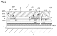
- a first and a second holding part 5, 6 are connected, wherein the in Fig. 3 . 4 and 5 detectable webs 501, 502, 601, 602 engage both in a bottom groove 201 and in a longitudinal groove 202 of the sight profile 2 to hold the sight profiles 2 and to secure the anchor profile 4 and 3, respectively.
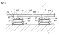
- the rail-shaped anchor profile 4 two upwardly open and undercut longitudinal grooves 401, 402. Since the first holding part 5, in the associated longitudinal groove 401 engageable guide element 503 and the second holding parts 6, in which it has associated longitudinal groove 402 engageable guide element 603, the holding parts 5, 6 are connected to the anchor profile 4. By such intervention, a simple and accurate positioning of the holding parts 5, 6 and thus the sight profiles 2 on the anchor profile 4 allows.
- the guide elements 503, 603 of the holding parts 5, 6 are slidable in these, whereby size changes of the sight profiles 2 in their transverse direction, such as caused by swelling and shrinkage of wood, are compensated. In this way, mechanical stress and stress of the device 1 can be intercepted or prevented, whereby an attachment of the visible profiles 2 is provided on the substrate 3 with high stability.
- the first holding part 5 is fixedly connected to the anchor profile 4 and the second holding part 6 relative to the first holding part 5 on the anchor profile 4 slidably mounted.
- the first holding part 5 is anchored via a thread-cutting screw 70 as a connecting means 7 in the longitudinal groove 401 of the anchor profile 4.
- the anchoring takes place up to the spring bars 403 of the anchor profile 4. This allows train or compressive loads acting on the overlying visual profile 2 to compensate.
- the screw 70 extends through the first guide element 503 of the first holding part 5.
- a continuous bore 504 in the first guide element 503 of the holding part 5 simplifies the handling of the connecting means 7 considerably.
- the second holding part 6, however, in the longitudinal groove 402 - practically free - slidably mounted.
- the position of the sight profile 2 is fixed to the first holding part 5, while the second holding part 6 allows horizontal compensating movements of the sight profile 2.
- This adaptability of the device 1 to material-related changes in size of the viewing profiles 2 again increases their stability.
- the web 602 extends maximally to the longitudinal side 203 of the sight profile - in the example it closes with this aligned -, whereby the second holding part 6 is covered by the sight profile 2 from above.
- the web 502 of the first holding part 5 is likewise covered by the sight profile 2, but not the first guide element 503 with the bore 504.
- the first guide element 503 and engaging in the longitudinal groove 202 of the sight profile 2 web 502 are arranged offset from each other in the longitudinal direction of the first holding member 5 and overlap in some areas. This allows screwing in the screw 70 for anchoring the first holding part 5 with the sighting profile 2 already fastened thereto.
- the screw 70 or the protruding part of the first holding part 5 is completely covered by the subsequently arranged sight profile 102 - with the aid of the staggered arrangement of the holding parts 5, 6 in the two longitudinal grooves 401, 402.
- Fig. 4 respectively.
- Fig. 5 show the holding parts 5, 6 in detail. It can be seen that the webs 501, 502 or 601, 602 and guide element 503 or 603 of the holding parts 5 and 6 are arranged on the opposite broad sides 505, 506 and 605, 606 of the holding parts 5 and 6 respectively.
- the guide element 503 and the web 502 are arranged offset to one another in the longitudinal direction of the first holding part 5. This allows a simple and inexpensive to be provided arrangement of the bore 504 by the guide member 503. Particularly advantageous is the aligned arrangement of the outer edge of web 502 and recess 507 has been found to accommodate the screw head, since so the web 502 when screwing the screw 70 as Leadership serves.
- the webs 501 and 601 for engaging in the bottom groove 201 of the sight profile 2 have a trapezoidal cross-section.
- the other second flank 509 or 609 is perpendicular from the broad side 505 or 605 from. Due to the first flank 508 or 608, the web 501 or 601, which otherwise has a rectangular cross section, tapers at right angles.
- the second higher web 502 or 602 for engaging in the longitudinal groove 202 of the sight profile 2 has an undercut 511 or 611 and a subsequent to this undercut 511 and 611 and projecting head 510 and 610, in the direction of the longitudinal groove 202nd has.
- This bead-shaped head 510, 610 is rounded to allow pivoting of the holding part 5, 6 in the groove 202.
- the undercut 511 or 611 improves the hold of the sight profile 2 on the relevant holding part 5, 6.
- the head 510, 610 pivotable into the groove 202 allows snapping the respective holding part 5, 6 onto the sight profile 2.
- the two webs 501, 502 and 601, 602 thus act with the sight profile 2 for training each a snap connection 204 together. This further simplifies the assembly of the sighting profiles 2, whereby working time and costs can be reduced.
- the holding force of the respective snap connection 204 is significantly improved by the height design of the first web 501, 601 of the respective holding parts 5, 6 for engagement in the respective bottom-side groove 201. Namely, the first webs 501, 601 of the respective holding parts 5, 6 project beyond the undercut 511, 611 on the second web 502, 602 of the respective holding parts 5, 6 at the web height 512, 612, which considerably complicates unwanted snap-out of the sight profile 2.
Landscapes
- Engineering & Computer Science (AREA)
- Architecture (AREA)
- Civil Engineering (AREA)
- Structural Engineering (AREA)
- Floor Finish (AREA)
- Adornments (AREA)
Applications Claiming Priority (1)
| Application Number | Priority Date | Filing Date | Title |
|---|---|---|---|
| ATA50446/2014A AT516000B1 (de) | 2014-06-26 | 2014-06-26 | Vorrichtung zur Befestigung eines Sichtprofils |
Publications (1)
| Publication Number | Publication Date |
|---|---|
| EP2960396A1 true EP2960396A1 (fr) | 2015-12-30 |
Family
ID=54035092
Family Applications (1)
| Application Number | Title | Priority Date | Filing Date |
|---|---|---|---|
| EP15174170.9A Withdrawn EP2960396A1 (fr) | 2014-06-26 | 2015-06-26 | Dispositif de fixation d'un profile de visualisation |
Country Status (2)
| Country | Link |
|---|---|
| EP (1) | EP2960396A1 (fr) |
| AT (1) | AT516000B1 (fr) |
Cited By (3)
| Publication number | Priority date | Publication date | Assignee | Title |
|---|---|---|---|---|
| KR102241675B1 (ko) * | 2020-07-03 | 2021-04-19 | 주식회사 에이치티 | 목재데크 팽창 방지형 데크로드 시스템 |
| KR102241670B1 (ko) * | 2020-07-03 | 2021-04-19 | 주식회사 에이치티 | 슬라이딩 회전 고정방식 데크로드 시스템 |
| WO2021074669A1 (fr) * | 2019-10-15 | 2021-04-22 | Liutkus Marius | Agrafe de fixation de premier et second éléments structuraux de tablier ou de bardage sur une structure de support et procédé associé |
Citations (5)
| Publication number | Priority date | Publication date | Assignee | Title |
|---|---|---|---|---|
| JP2002161632A (ja) * | 2000-11-22 | 2002-06-04 | Sanyo Industries Ltd | 床敷設構造 |
| US20060156664A1 (en) * | 2002-05-30 | 2006-07-20 | Chae Wan S | Installation method of panel and rail-type fixing apparatus |
| DE202007002282U1 (de) * | 2007-02-16 | 2008-06-19 | Möller GmbH & Co. KG | Profilelemente |
| DE102008048560A1 (de) | 2008-09-23 | 2010-03-25 | Knapp, Friedrich | Beschlag zur Herstellung eines Bodenaufbaus |
| DE202013102695U1 (de) | 2013-06-21 | 2013-07-01 | Reifenhäuser GmbH & Co. KG Maschinenfabrik | Profil z.B. für einen Terrassenbelag |
Family Cites Families (1)
| Publication number | Priority date | Publication date | Assignee | Title |
|---|---|---|---|---|
| CN102373783A (zh) * | 2010-08-10 | 2012-03-14 | 吕锋滨 | 一种用于电热地板的连接构件 |
-
2014
- 2014-06-26 AT ATA50446/2014A patent/AT516000B1/de active
-
2015
- 2015-06-26 EP EP15174170.9A patent/EP2960396A1/fr not_active Withdrawn
Patent Citations (5)
| Publication number | Priority date | Publication date | Assignee | Title |
|---|---|---|---|---|
| JP2002161632A (ja) * | 2000-11-22 | 2002-06-04 | Sanyo Industries Ltd | 床敷設構造 |
| US20060156664A1 (en) * | 2002-05-30 | 2006-07-20 | Chae Wan S | Installation method of panel and rail-type fixing apparatus |
| DE202007002282U1 (de) * | 2007-02-16 | 2008-06-19 | Möller GmbH & Co. KG | Profilelemente |
| DE102008048560A1 (de) | 2008-09-23 | 2010-03-25 | Knapp, Friedrich | Beschlag zur Herstellung eines Bodenaufbaus |
| DE202013102695U1 (de) | 2013-06-21 | 2013-07-01 | Reifenhäuser GmbH & Co. KG Maschinenfabrik | Profil z.B. für einen Terrassenbelag |
Cited By (3)
| Publication number | Priority date | Publication date | Assignee | Title |
|---|---|---|---|---|
| WO2021074669A1 (fr) * | 2019-10-15 | 2021-04-22 | Liutkus Marius | Agrafe de fixation de premier et second éléments structuraux de tablier ou de bardage sur une structure de support et procédé associé |
| KR102241675B1 (ko) * | 2020-07-03 | 2021-04-19 | 주식회사 에이치티 | 목재데크 팽창 방지형 데크로드 시스템 |
| KR102241670B1 (ko) * | 2020-07-03 | 2021-04-19 | 주식회사 에이치티 | 슬라이딩 회전 고정방식 데크로드 시스템 |
Also Published As
| Publication number | Publication date |
|---|---|
| AT516000B1 (de) | 2016-06-15 |
| AT516000A1 (de) | 2016-01-15 |
Similar Documents
| Publication | Publication Date | Title |
|---|---|---|
| DE102008018072B3 (de) | Vorrichtung zum Verlegen von Brettern für z.B. Terrassenbeläge | |
| DE102016121074B3 (de) | Sammelschienenhalter und eine entsprechende Anordnung | |
| DE102016000829A1 (de) | Vorrichtung zur Befestigung und/oder Ausrichtung von Bodenbelägen | |
| AT510695B1 (de) | Beschlag für das verbinden der bohlen einer terrassenabdeckung mit einer darunterliegenden unterkonstruktion | |
| AT516000B1 (de) | Vorrichtung zur Befestigung eines Sichtprofils | |
| EP0439716A1 (fr) | Ancre pour fixer des plaques de façade sur un mur | |
| AT414029B (de) | Befestigung von bohlen an einer unterkonstruktion | |
| EP3121347B1 (fr) | Pièce de retenue | |
| DE202010012937U1 (de) | Befestigungssystem | |
| DE102009056332A1 (de) | Verbindungselement für Stützen | |
| DE102016124988B4 (de) | Beschlag und Verfahren für das Verlegen von Terrassendielen | |
| LU82030A1 (de) | Klemme fuer ein zugaengliches demontierbares tragsystem einer aus tafeln bestehenden wandverkleidung | |
| DE19903133C2 (de) | System zur Befestigung von Täfelungsplatten, wie Paneelen, Profilbrettern, und Nut- und Federbrettern vor Wänden, Decken oder Böden | |
| DE102007009667B4 (de) | Profilkonstruktion | |
| DE102018127768B4 (de) | Beschlag sowie Befestigungsset | |
| DE69813106T2 (de) | Vorrichtung zum gegenseitigen Verbinden flacher Elemente, insbesondere für den Zusammenbau von Möbelstücken | |
| AT515666B1 (de) | Vorrichtung zur Befestigung von Sichtprofilen | |
| DE102021107547B4 (de) | Montageset zur Montage eines Rahmens an einer Öffnung eines Verankerungsgrunds mittels biegestabiler Verbindung zwischen Konsolenprofil und Anbauteil, sowie Anordnung und Verfahren hierfür | |
| WO2020001763A1 (fr) | Protection latérale pour toit plat | |
| DE4201515C2 (de) | Vorrichtung zur Befestigung eines Plattenelements an einer Wand | |
| EP0055861A1 (fr) | Dispositif de fixation pour meubles | |
| EP2604868B1 (fr) | Dispositif et procédé destinés à la liaison de composants | |
| DE20000552U1 (de) | Profilschienensystem | |
| CH679685A5 (fr) | ||
| EP4560104A1 (fr) | Dispositif de montage d'un dispositif de réception pour au moins un moyen de fixation d'une fixation de rebord de fenêtre dans un mur ainsi que module correspondant |
Legal Events
| Date | Code | Title | Description |
|---|---|---|---|
| PUAI | Public reference made under article 153(3) epc to a published international application that has entered the european phase |
Free format text: ORIGINAL CODE: 0009012 |
|
| AK | Designated contracting states |
Kind code of ref document: A1 Designated state(s): AL AT BE BG CH CY CZ DE DK EE ES FI FR GB GR HR HU IE IS IT LI LT LU LV MC MK MT NL NO PL PT RO RS SE SI SK SM TR |
|
| AX | Request for extension of the european patent |
Extension state: BA ME |
|
| 17P | Request for examination filed |
Effective date: 20160630 |
|
| RBV | Designated contracting states (corrected) |
Designated state(s): AL AT BE BG CH CY CZ DE DK EE ES FI FR GB GR HR HU IE IS IT LI LT LU LV MC MK MT NL NO PL PT RO RS SE SI SK SM TR |
|
| GRAJ | Information related to disapproval of communication of intention to grant by the applicant or resumption of examination proceedings by the epo deleted |
Free format text: ORIGINAL CODE: EPIDOSDIGR1 |
|
| GRAP | Despatch of communication of intention to grant a patent |
Free format text: ORIGINAL CODE: EPIDOSNIGR1 |
|
| GRAP | Despatch of communication of intention to grant a patent |
Free format text: ORIGINAL CODE: EPIDOSNIGR1 |
|
| RIN1 | Information on inventor provided before grant (corrected) |
Inventor name: HAMMINGER, DANIEL |
|
| INTG | Intention to grant announced |
Effective date: 20170621 |
|
| GRAJ | Information related to disapproval of communication of intention to grant by the applicant or resumption of examination proceedings by the epo deleted |
Free format text: ORIGINAL CODE: EPIDOSDIGR1 |
|
| INTC | Intention to grant announced (deleted) | ||
| GRAP | Despatch of communication of intention to grant a patent |
Free format text: ORIGINAL CODE: EPIDOSNIGR1 |
|
| INTG | Intention to grant announced |
Effective date: 20180109 |
|
| STAA | Information on the status of an ep patent application or granted ep patent |
Free format text: STATUS: THE APPLICATION IS DEEMED TO BE WITHDRAWN |
|
| 18D | Application deemed to be withdrawn |
Effective date: 20180523 |