EP2960498A2 - Schnell modulierte, hydraulische versorgung für eine robotervorrichtung - Google Patents
Schnell modulierte, hydraulische versorgung für eine robotervorrichtung Download PDFInfo
- Publication number
- EP2960498A2 EP2960498A2 EP15166667.4A EP15166667A EP2960498A2 EP 2960498 A2 EP2960498 A2 EP 2960498A2 EP 15166667 A EP15166667 A EP 15166667A EP 2960498 A2 EP2960498 A2 EP 2960498A2
- Authority
- EP
- European Patent Office
- Prior art keywords
- chamber
- flow rate
- displacement member
- hydraulic supply
- motion
- Prior art date
- Legal status (The legal status is an assumption and is not a legal conclusion. Google has not performed a legal analysis and makes no representation as to the accuracy of the status listed.)
- Granted
Links
Images




Classifications
-
- F—MECHANICAL ENGINEERING; LIGHTING; HEATING; WEAPONS; BLASTING
- F04—POSITIVE - DISPLACEMENT MACHINES FOR LIQUIDS; PUMPS FOR LIQUIDS OR ELASTIC FLUIDS
- F04B—POSITIVE-DISPLACEMENT MACHINES FOR LIQUIDS; PUMPS
- F04B9/00—Piston machines or pumps characterised by the driving or driven means to or from their working members
- F04B9/02—Piston machines or pumps characterised by the driving or driven means to or from their working members the means being mechanical
- F04B9/025—Driving of pistons coacting within one cylinder
-
- F—MECHANICAL ENGINEERING; LIGHTING; HEATING; WEAPONS; BLASTING
- F04—POSITIVE - DISPLACEMENT MACHINES FOR LIQUIDS; PUMPS FOR LIQUIDS OR ELASTIC FLUIDS
- F04B—POSITIVE-DISPLACEMENT MACHINES FOR LIQUIDS; PUMPS
- F04B3/00—Machines or pumps with pistons coacting within one cylinder, e.g. multi-stage
- F04B3/003—Machines or pumps with pistons coacting within one cylinder, e.g. multi-stage with two or more pistons reciprocating one within another, e.g. one piston forning cylinder of the other
-
- F—MECHANICAL ENGINEERING; LIGHTING; HEATING; WEAPONS; BLASTING
- F04—POSITIVE - DISPLACEMENT MACHINES FOR LIQUIDS; PUMPS FOR LIQUIDS OR ELASTIC FLUIDS
- F04B—POSITIVE-DISPLACEMENT MACHINES FOR LIQUIDS; PUMPS
- F04B49/00—Control, e.g. of pump delivery, or pump pressure of, or safety measures for, machines, pumps, or pumping installations, not otherwise provided for, or of interest apart from, groups F04B1/00 - F04B47/00
- F04B49/22—Control, e.g. of pump delivery, or pump pressure of, or safety measures for, machines, pumps, or pumping installations, not otherwise provided for, or of interest apart from, groups F04B1/00 - F04B47/00 by means of valves
-
- F—MECHANICAL ENGINEERING; LIGHTING; HEATING; WEAPONS; BLASTING
- F17—STORING OR DISTRIBUTING GASES OR LIQUIDS
- F17C—VESSELS FOR CONTAINING OR STORING COMPRESSED, LIQUEFIED OR SOLIDIFIED GASES; FIXED-CAPACITY GAS-HOLDERS; FILLING VESSELS WITH, OR DISCHARGING FROM VESSELS, COMPRESSED, LIQUEFIED, OR SOLIDIFIED GASES
- F17C13/00—Details of vessels or of the filling or discharging of vessels
- F17C13/04—Arrangement or mounting of valves
-
- F—MECHANICAL ENGINEERING; LIGHTING; HEATING; WEAPONS; BLASTING
- F15—FLUID-PRESSURE ACTUATORS; HYDRAULICS OR PNEUMATICS IN GENERAL
- F15B—SYSTEMS ACTING BY MEANS OF FLUIDS IN GENERAL; FLUID-PRESSURE ACTUATORS, e.g. SERVOMOTORS; DETAILS OF FLUID-PRESSURE SYSTEMS, NOT OTHERWISE PROVIDED FOR
- F15B11/00—Servomotor systems without provision for follow-up action; Circuits therefor
- F15B11/08—Servomotor systems without provision for follow-up action; Circuits therefor with only one servomotor
- F15B11/12—Servomotor systems without provision for follow-up action; Circuits therefor with only one servomotor providing distinct intermediate positions; with step-by-step action
- F15B11/13—Servomotor systems without provision for follow-up action; Circuits therefor with only one servomotor providing distinct intermediate positions; with step-by-step action using separate dosing chambers of predetermined volume
-
- Y—GENERAL TAGGING OF NEW TECHNOLOGICAL DEVELOPMENTS; GENERAL TAGGING OF CROSS-SECTIONAL TECHNOLOGIES SPANNING OVER SEVERAL SECTIONS OF THE IPC; TECHNICAL SUBJECTS COVERED BY FORMER USPC CROSS-REFERENCE ART COLLECTIONS [XRACs] AND DIGESTS
- Y10—TECHNICAL SUBJECTS COVERED BY FORMER USPC
- Y10T—TECHNICAL SUBJECTS COVERED BY FORMER US CLASSIFICATION
- Y10T137/00—Fluid handling
- Y10T137/0318—Processes
- Y10T137/0396—Involving pressure control
-
- Y—GENERAL TAGGING OF NEW TECHNOLOGICAL DEVELOPMENTS; GENERAL TAGGING OF CROSS-SECTIONAL TECHNOLOGIES SPANNING OVER SEVERAL SECTIONS OF THE IPC; TECHNICAL SUBJECTS COVERED BY FORMER USPC CROSS-REFERENCE ART COLLECTIONS [XRACs] AND DIGESTS
- Y10—TECHNICAL SUBJECTS COVERED BY FORMER USPC
- Y10T—TECHNICAL SUBJECTS COVERED BY FORMER US CLASSIFICATION
- Y10T137/00—Fluid handling
- Y10T137/8593—Systems
- Y10T137/85978—With pump
Definitions
- exoskeleton, humanoid, and other legged robot systems exist.
- the fundamental technical problem to be solved for such systems, where energetic autonomy is concerned, is power.
- Two options are available: use a high-output power supply that can meet the demands of the robotic system, or use less power.
- the first option lacks practicality, inasmuch as portable power remains a challenge, which leaves the second option.
- the exoskeletons or ambulatory robots currently in existence are not capable of providing high force outputs for prolonged periods of time.
- the power issue has been a challenging obstacle, with the typical solution being to reduce the force output capabilities of the system.
- the term “substantially” refers to the complete or nearly complete extent or degree of an action, characteristic, property, state, structure, item, or result.
- an object that is “substantially” enclosed would mean that the object is either completely enclosed or nearly completely enclosed.
- the exact allowable degree of deviation from absolute completeness may in some cases depend on the specific context. However, generally speaking the nearness of completion will be so as to have the same overall result as if absolute and total completion were obtained.
- the use of “substantially” is equally applicable when used in a negative connotation to refer to the complete or near complete lack of an action, characteristic, property, state, structure, item, or result.
- adjacent refers to the proximity of two structures or elements. Particularly, elements that are identified as being “adjacent” may be either abutting or connected. Such elements may also be near or close to each other without necessarily contacting each other. The exact degree of proximity may in some cases depend on the specific context.
- a rapidly modulated hydraulic supply for a new robotic system improves efficiency over a hydraulic supply of a typical robotic system.
- flow rate is variable to produce pressures and flow suitable to meet the instantaneous demands of the robotic system.
- the rapidly modulated hydraulic supply can include a chamber for receiving fluid.
- the rapidly modulated hydraulic supply can also include a displacement member operable to displace the fluid from the chamber.
- the rapidly modulated hydraulic supply can include a flow modulation system operable to vary the flow rate of the fluid output from the chamber.
- a first flow rate corresponds to a first output pressure, and is different from a second flow rate corresponding to a second output pressure for a like or similar movement of the displacement member.
- the robotic device 100 can be configured as an exoskeleton structure for attachment to a human body or as a humanoid robot and can be used in applications relevant to the military, first responders, the commercial sector, etc.
- the robotic device 100 can include support members coupled together for relative movement defining degrees of freedom, which can correspond to degrees of freedom of a human extremity.
- a human user or operator may use or interact with the robotic device 100 by placing his or her feet into a foot portion of the device, where the feet of the operator can be in contact with a corresponding force sensor. Portions of the human operator can also be in contact with force sensors disposed on various locations of the robotic device 100. For example, a hip portion or a shoulder portion of the robotic device 100 can have a force sensor configured to interact with the operator's hip or shoulder, respectively.
- the operator can be coupled to the robotic device 100 by a waist strap, shoulder strap or other appropriate coupling device.
- the operator can be further coupled to the robotic device 100 by a foot strap and/or a handle for the operator to grasp.
- a force sensor can be located about a knee portion or an elbow portion of the legged robotic device 100 near a knee or a shoulder, respectively, of the operator. While reference is made to force sensors disposed at specific locations on or about the legged robotic device 100, it should be understood that force sensors can be strategically placed at numerous locations on or about the robotic device 100 in order to facilitate proper operation of the robotic device 100.
- FIG. 2 is a schematic illustration of a power system 101 for the robotic device 100.
- the power system 101 can include an energy source 110, such as a battery, a turbine generator, a fossil fuel, and others to provide energy for a prime mover 111, which can be an electric motor, an internal combustion engine, for example.
- the prime mover 111 can be mechanically and/or electrically coupled to a rapidly modulated hydraulic supply 112, which can serve as a hydraulic pump to provide pressurized fluid for hydraulic actuators 113a-c used to actuate one or more degrees of freedom of the robotic device 100.
- the rapidly modulated hydraulic supply 112 can be fluidly connected to the actuators 113a-c via a fluid bus 114.
- a single rapidly modulated hydraulic supply 112 can provide fluid for any number or combination of actuators to actuate degrees of freedom of the robotic device 100.
- a single rapidly modulated hydraulic supply 112 can be configured to provide pressurized fluid for all the actuators of a leg or arm of the robotic device, a side (i.e., right or left) of the robotic device 100, or a grouping of extremities (i.e., both legs or both arms) of the robotic device 100.
- a control system 115 can be configured to control operation of the prime mover 111, the rapidly modulated hydraulic supply 112, and/or the actuators 113a-c based on, at least in part, input from the various sensors disposed about the robotic device 100, such as to facilitate efficient operation of the robotic device 100 as discussed in more detail below.
- variable hydraulic pressure can be utilized to minimize waste and improve performance efficiencies.
- the rapidly modulated hydraulic supply 112 can vary the supply pressure dynamically, thus providing only a hydraulic system pressure that is needed at any given time. Otherwise, as is the case with typical robotic systems, energy is wasted and heat is generated. For example, in the case of the robotic device 100 of FIG.
- the rapidly modulated hydraulic supply 112 can dynamically vary the pressure to supply what is needed for the two robotic legs to operate.
- the pressure required by the actuators varies over time.
- a "pressure profile” which is pressure as a function of time, fluctuates as the robotic device 100 performs different movements and tasks. For example, in a walking motion, higher pressure would be provided as the leg contacts the ground following a swinging motion (where the pressure is low). Dynamically varying the pressure to substantially match the pressure profile and supply what is needed through the walking motion can reduce the amount of waste.
- the power system 101 can be configured to account for these and dynamically vary pressure across differing operational situations or conditions.
- one advantage of the power system 101 is a reduction of the pressure needed to operate the robotic device 100.
- One exemplary way to dynamically vary pressure in the hydraulic system is to configure the power system 101 such that the rapidly modulated hydraulic supply 112 operates both legs so as to reduce the power requirements for each leg.
- Another example configuration of the power system 101 is to include two rapidly modulated hydraulic supplies 112, utilizing one rapidly modulated hydraulic supply 112 per leg. In this case, the pressure profile of each leg can be followed continuously over time. Doing this can reduce the power requirements even further over the previous example where only a single variable hydraulic supply is provided because optimization can occur on a per leg basis.
- FIG. 3 is a schematic illustration of a hydraulic system 102 of the power system 101.
- the hydraulic system 102 can include the rapidly modulated hydraulic supply 112 and one of the actuators 113 for actuating a degree of freedom of the robotic device 100, which is coupled to the rapidly modulated hydraulic supply 112 via the fluid bus 114 or other suitable hydraulic line. Fluid from actuator 113 can return to a reservoir 116, from which fluid can be provided to the rapidly modulated hydraulic supply 112.
- check valves 117a, 117b coupled to an outlet and an inlet of the hydraulic supply 112, respectively, can ensure proper fluid flow into and out of the hydraulic supply 112.
- the hydraulic system 102 can also include an accumulator 118 to accommodate pressure fluctuations (i.e., store energy to support power transients) in the fluid bus 114 or fluid supply line and provide flow smoothing.
- pressure fluctuations i.e., store energy to support power transients
- the hydraulic system 102 can also include an accumulator 118 to accommodate pressure fluctuations (i.e., store energy to support power transients) in the fluid bus 114 or fluid supply line and provide flow smoothing.
- the rapidly modulated hydraulic supply 112 can include a chamber 120 for receiving fluid from the reservoir 116.
- the hydraulic supply 112 can also include a displacement member 121 operable to displace the fluid from the chamber 120.
- the hydraulic supply 112 can include a flow modulation system 122 operable to vary the flow rate of the fluid output from the hydraulic supply 112.
- a first flow rate corresponds to a first output pressure, and is different from a second flow rate corresponding to a second output pressure for a similar or like movement of the displacement member 121.
- the displacement member 121 can move with a consistent stroke length throughout operation of the hydraulic supply 112 and due to the flow modulation system 122, the flow rate provided by the hydraulic supply 112 can vary.
- the rate at which the displacement member 121 cycles within the chamber 120 can remain substantially constant and the flow modulation system 122 can cause the flow to vary.
- the flow modulation system 122 can effectively modulate the flow rate of the hydraulic supply 112 independent of the action or motion of the displacement member 121.
- the prime mover 111 can be operated at near constant speed and average power input, thereby largely eliminating inertia related losses associated with accelerating and decelerating the prime mover 111 and/or the hydraulic supply 112.
- output pressure of the hydraulic supply 112 can be controlled by modulating the flow rate from the hydraulic supply 112, and as a consequence the accumulator 118 charge level.
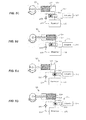
- FIGS. 4A-4D illustrate a rapidly modulated hydraulic supply 212 in accordance an example of the present disclosure.
- Hydraulic fluid plumbing and valving features or components such as inlet and outlet lines, check valves, etc., have been omitted for clarity.
- the hydraulic supply 212 includes a chamber 220, a displacement member 221, and a flow modulation system 222.
- the chamber 220 can comprise a cylinder and the displacement member 221 can comprise a piston disposed in the cylinder and configured for reciprocal or cyclical movement therein.
- the displacement member 221 can be coupled to a crankshaft 230 via a connecting rod 231, which can cause the displacement member 221 to move within the chamber 220 as the crankshaft rotates in direction 232.
- a flywheel 233 can be associated with the crankshaft 230 to provide energy storage for transient operation.
- the flow modulation system 222 can include a first portion 240 of the piston and a second portion 241 of the piston, which are moveable relative to one another.
- the second portion 241 of the piston can form a sleeve about at least a part of the first portion 240 of the piston.
- the flow modulation system 222 can also include a coupling mechanism 242, which can include a pin 243, configured to selectively couple and uncouple the first portion 240 and the second portion 241 of the piston to/from one another.
- the coupling mechanism 242 can include an actuator 244 (e.g., a solenoid, an electric motor, a pneumatic actuator, and/or a hydraulic actuator), to cause the pin 243 to couple and uncouple the first portion 240 and the second portion 241 of the piston.
- the actuator 244 can cause the pin 243 to move in direction 245 ( FIG. 4A ) to couple the first portion 240 and the second portion 241 of the piston to one another, and the actuator 244 can cause the pin 243 to move in direction 246 ( FIG. 4C ) to uncouple the first portion 240 and the second portion 241 of the piston from one another.
- the piston can have a variable piston area or can provide a variable displacement, thus providing the hydraulic supply 212 with a variable geometry.
- coupling and uncoupling of the first portion 240 and the second portion 241 of the piston can occur at bottom dead center, as shown in FIGS. 4A and 4C , where the movable piston portions 240, 241 are at or near zero velocity and loading on the piston portions 240, 241 is at a minimum.
- both portions are caused to move together ( FIG. 4B ) as forces from the crankshaft are transferred to both the first and second portions 240, 241 via the pin 243.
- reciprocal movement of the first portion 240 and the second portion 241 of the piston provides a first flow rate from the hydraulic supply 212.
- the first portion 240 and the second portion 241 of the piston are uncoupled from one another ( FIG. 4D ) the first portion 240 moves independently of the second portion as no forces from the crankshaft are transferred to the second portion 241.
- the second portion 241 can be held stationary and reciprocal movement of the first portion 240 of the piston provides a second flow rate from the hydraulic supply 212, which is lower than the first flow rate, due to the relatively smaller pumping displacement provided by the first portion 240 of the piston alone.
- the actuator 244 can be controlled to rapidly insert and remove the pin 243 to couple and uncouple the first and second portions 240, 241 on any given cycle of the piston to vary the flow rate as desired.
- the actuator 244 can require a low power to operate, thereby minimizing the power required to modulate the flow rate provided by the hydraulic supply 212.
- FIGS. 5A-5D illustrate a rapidly modulated hydraulic supply 312 in accordance another example of the present disclosure.
- the hydraulic supply 312 includes a chamber 320, a displacement member 321, and a flow modulation system 322.
- the chamber 320 can comprise a cylinder and the displacement member 321 can comprise a piston disposed in the cylinder and configured for reciprocal or cyclical movement therein.
- the flow modulation system 322 can include a valve 350, which can be a high throughput valve, between the chamber 320 and a fluid reservoir 316 configured to selectively open and close.
- An actuator 344 can be included to cause the valve 350 to open and close.
- the actuator 344 can comprise a solenoid.
- reciprocal movement of the displacement member 321 provides substantially no fluid output from the chamber 320, and therefore the hydraulic supply 312 is not pumping fluid.
- the prime mover can operate at low power, thus providing a power savings.
- the valve 350 can be opened and closed when the displacement member 321 is at bottom dead center, as shown in FIGS. 5A and 5C , where the displacement member 321 is at or near zero velocity and loading on the displacement member 321 is at a minimum.
- the valve 350 can comprise a one-way or check valve to prevent fluid from being forced by the displacement member 321 back to the reservoir 316 when pumping.
- a check valve can be located at 352 between the chamber 320 and the valve 350 to prevent fluid from being forced by the displacement member 321 back to the reservoir 316 when pumping.
- a check valve 353 can be included in a fluid conduit 354 coupling the reservoir 316 and the chamber 320, such that the check valve 353 is in parallel with the valve 350 between the reservoir 316 and the chamber 320.
- the valve 350 when the valve 350 is closed to prevent the flow of fluid therethrough ( FIGS. 5C and 5D ), reciprocal movement of the displacement member 321 draws fluid from the fluid reservoir 316 into the chamber 320 via the fluid conduit 354 and the check valve 353 and provides a first flow rate from hydraulic supply 312. Therefore, the hydraulic supply 312 is pumping fluid.
- FIGS. 5C and 5D When the valve 350 is closed to prevent the flow of fluid therethrough ( FIGS. 5C and 5D ), reciprocal movement of the displacement member 321 draws fluid from the fluid reservoir 316 into the chamber 320 via the fluid conduit 354 and the check valve 353 and provides a first flow rate from hydraulic supply 312. Therefore, the hydraulic supply 312 is pumping fluid.
- FIGS. 5C and 5D When the valve 350 is closed to prevent the flow
- reciprocal movement of the displacement member 321 draws fluid into the chamber 320 and forces fluid from the chamber 320 via the valve 350, such that the displacement member 321 provides substantially no fluid output from the chamber 320. Therefore, the hydraulic supply 312 is not pumping fluid.
- the actuator 344 can be controlled to rapidly open and close the valve 350 to permit or prevent pumping on any given cycle of the displacement member 321 to vary the flow rate as desired.
- selective opening and closing of the valve 350 can provide a second flow rate provided by the hydraulic supply 312.
- the actuator 344 can require a low power to operate, thereby minimizing the power required to modulate the flow rate provided by the hydraulic supply 312.
- FIGS. 6A-6D illustrate a rapidly modulated hydraulic supply 412 in accordance yet another example of the present disclosure.
- Hydraulic fluid plumbing and valving features or components such as inlet and outlet lines, check valves, etc., have been omitted for clarity.
- the hydraulic supply 412 includes a chamber 420, a displacement member 421, and a flow modulation system 422.
- the chamber 420 can comprise a cylinder and the displacement member 421 can comprise a piston disposed in the cylinder and configured for reciprocal or cyclical movement therein.
- the flow modulation system 422 can include a moveable head 460 disposed in the chamber 420 and opposed to the displacement member 421.
- the movable head 460 can be movable in a direction 464, parallel with a movement direction of the displacement member 421, within the chamber 420.
- the flow modulation system 422 can also include a range of motion limitation mechanism 461 to limit a range of motion of the moveable head 460 in the chamber 420 between a first range of motion and a second range of motion.
- the range of motion limitation mechanism 461 can comprise a movable stop member 462.
- An actuator 444 can be included to cause the movable stop member 462 to move, as described in more detail below.
- the actuator 444 can comprise a solenoid.
- the movable stop member 462 can be operable with the movable head 460 to provide the first range of motion at a first position (e.g., as in FIGS. 6A and 6B ) and the second range of motion at a second position (e.g., as in FIGS. 6C and 6D ).
- the movable stop member 462 can be movable relative to the movable head 460, such as in a direction 465, which may be perpendicular to the direction 464 of the movable head 460.
- the movable stop member 462 can be configured to interface with the movable head 460, or a component extending therefrom, to provide a stop for the movable head 460, which can establish or define a range of motion for the movable head 460.
- the movable stop member 462 can have a wedge configuration, as shown, or any other suitable configuration.
- the range of motion of the movable head 460 can vary based on a relative (i.e., lateral) position of the movable stop member 462 and the movable head 460.
- the movable head 460 can be prevented from moving.
- the first range of motion of the movable head is zero.
- the hydraulic supply 412 can function to provide a high output in this configuration with the wedge configuration of the movable stop member 462 fully inserted.
- the first range of motion can be such that movement of the displacement member 421 is operable with the movable head 460 to provide a first flow rate from the hydraulic supply 412.
- the movable stop member 462 when the movable stop member 462 is at the position shown in FIGS. 6C and 6D , with a narrow portion of the wedge configuration engaged with the movable head 460 or the movable member 462 is retracted or withdrawn such that no contact occurs between the movable head 460 and the movable stop member 462, the movable head 460 may move within the chamber 420 as limited by the second range of motion. With the movable head 460 movable relative to the chamber 420 as shown in FIGS. 6C and 6D , reciprocal movement of the displacement member 421 within the chamber 420 is less effective or ineffective to pump fluid from the hydraulic supply 412 as the pressure created by the displacement member 421 is absorbed by the movable head 460.
- the second range of motion can be such that movement of the displacement member 421 is operable with the movable head 460 to provide a second flow rate from the hydraulic supply 412, which is lower than the first flow rate, depending upon the position of the movable stop member 462. In some cases, the second flow rate may be zero.
- the movable head 460 can be biased toward the displacement member 421, such that the movable head 460 can move with the displacement member 421 within the available range of motion.
- a spring 463 can be included to bias the movable head 460 toward the displacement member 421. In this scenario, only a portion of the pressure is lost by movement of the movable head 460, with some of the pressure acting to provide the second flow rate above zero, but still at a lower pressure than the first flow rate.
- the actuator 444 can be controlled to rapidly insert and retract the movable stop member 462 to permit or reduce/prevent pumping on any given cycle of the displacement member 421 to vary the flow rate as desired, depending upon the selected position of the movable stop member 462.
- the movable stop member 462 can be selectively inserted and retracted to provide a desired flow rate from the hydraulic supply 412.
- the actuator 444 can require a low power to operate, thereby minimizing the power required to modulate the flow rate provided by the hydraulic supply 412.
- FIGS. 7A-7D illustrate a rapidly modulated hydraulic supply 512 in accordance yet another example of the present disclosure.
- the hydraulic supply 512 includes a chamber 520, a displacement member 521, and a flow modulation system 522.
- the chamber 520 can comprise a cylinder and the displacement member 521 can comprise a piston disposed in the cylinder and configured for reciprocal or cyclical movement therein.
- the flow modulation system 522 can include an inlet valve 570 between the chamber 520 and a fluid reservoir 516.
- the inlet valve 570 can be movable in a direction 564, parallel with a movement direction of the displacement member 521.
- the flow modulation system 522 can also include a range of motion limitation mechanism 561 to limit a range of motion for the inlet valve 570 between a first range of motion and a second range of motion.
- the range of motion limitation mechanism 561 can comprise a movable stop member 562.
- An actuator 544 can be included to cause the movable stop member 562 to move, as described in more detail below.
- the actuator 544 can comprise a solenoid.
- the movable stop member 562 can be operable with the inlet valve 570 to provide the first range of motion at a first position (e.g., as in FIGS. 7A and 7B ) and the second range of motion at a second position (e.g., as in FIGS. 7C and 7D ).
- the movable stop member 562 can be movable relative to the inlet valve 570, such as in a direction 565, which may be perpendicular to the direction 564 of the inlet valve 570.
- the movable stop member 562 can be configured to interface with the inlet valve 570 to provide a stop for the inlet valve 570, which can establish or define a range of motion for the inlet valve 570 between the movable stop member 562 and a valve seat 571.
- the movable stop member 562 can have a wedge configuration, as shown, or any other suitable configuration.
- the range of motion of the inlet valve 570 can vary based on a relative (i.e., lateral) position of the movable stop member 562 and the inlet valve 570.
- the inlet valve 570 may move from the valve seat 571 to the movable stop member 562 a distance that facilitates a higher output pumping operation of the displacement member 521 within the chamber 520 (as compared to the scenario where the inlet valve is caused to travel a greater distance from the valve seat, as described below and shown in FIGS. 7C and 7D ).
- the inlet valve 570 can open and close in a manner that facilitates a higher volume of fluid being pumped.
- the first range of motion established by the movable stop member 562 can facilitate closing of the inlet valve 570 such that movement of the displacement member 521 is operable to provide a first flow rate from the hydraulic supply 512.
- the inlet valve 570 may move within the chamber 520 between the valve seat 571 and the movable stop member 562 as limited by the second range of motion. With the inlet valve 570 movable relative to the chamber 520 as shown in FIGS.
- reciprocal movement of the displacement member 521 within the chamber 520 is less effective, and may be completely ineffective, to pump fluid from the hydraulic supply 512, because as the displacement member 521 moves to generate pressure within the chamber 520 fluid can escape the chamber 520 via the valve 570 due to the large gap between the valve 570 and the valve seat 571.
- a reduced amount or no pressure can be created within the chamber 520 by movement of the displacement member 521 when the inlet valve 570 is allowed to move toward or to the extent shown in FIGS. 7C and 7D .
- the second range of motion established by the movable stop member 562 can facilitate closing of the inlet valve 570 (i.e., by causing it to travel a greater distance to close) such that movement of the displacement member 521 is operable to provide a second flow rate lower than the first flow rate, depending upon the position of the movable stop member 562.
- the second flow rate may be zero.
- the actuator 544 can be controlled to rapidly insert and retract the movable stop member 562 to various positions to permit or prevent pumping on any given cycle of the displacement member 521 and to vary the flow rate as desired.
- the movable stop member 562 can be selectively inserted and retracted to provide a desired flow rate from the hydraulic supply 512.
- the actuator 544 can require a low power to operate, thereby minimizing the power required to modulate the flow rate provided by the hydraulic supply 512.
- FIG. 8 illustrates a rapidly modulated hydraulic supply 612 in accordance yet another example of the present disclosure.
- the hydraulic supply 612 includes a chamber 620, a displacement member 621, and a flow modulation system 622.
- the flow modulation system 622 can include an accumulator 680 and an actuator 644 (e.g., a solenoid, an electric motor, a pneumatic actuator, and/or a hydraulic actuator).
- the accumulator 680 can include a chamber 682 to receive fluid in the hydraulic system and a piston 683 to exert a force against the fluid in the chamber 682.
- the actuator 644 can be coupled to the piston 683.
- a spring 684 can be coupled to the piston 683 between the piston 683 and the actuator 644.
- the accumulator 680 can function as a normal piston type accumulator.
- the actuator 644 can be controlled to rapidly extend and retract the piston 683 to various positions within the chamber 682 to vary the pressure in the system as desired.
- the piston 683 can be selectively extended and retracted to provide a desired pressure from the hydraulic supply 612.
- the spring 683 can smooth the application and removal of pressure to the fluid when the actuator 644 causes the piston 683 to move within the chamber 682.
- the actuator 644 can require a low power to operate, thereby minimizing the power required to modulate the flow rate provided by the hydraulic supply 612.
- a rapidly modulated hydraulic supply as disclosed herein can provide rapid and efficient flow modulation to vary hydraulic system pressure dynamically to follow the instantaneous or average demand of the system (which may include some pressure/power overhead).
- the supply pressure and hydraulic power can be modulated to track the instantaneous demand of the actuators, while performing tasks such as walking and running with a load.
- Varying the supply pressure to optimally adjust system pressure to meet system demands at any given moment in time can save power and minimize undesirable heat generation. For example, by operating with the control ports nearly fully open, orifice losses (e.g., large pressure drops at high flow across pressure regulators and servo-valves used to control joint movement and torque) can be reduced, which minimizes power dissipation while the actuators generate positive power. In addition, the large power losses across pressure regulators are, for the most part, eliminated.
- a method for facilitating pressure and flow rate modulation of a hydraulic supply to track the present demand of an actuator can comprise providing a chamber for receiving fluid.
- the method can also comprise providing a displacement member operable to displace the fluid from the chamber.
- the method can comprise facilitating variable flow rates of the fluid output from the chamber, wherein a first flow rate corresponds to a first output pressure, and is different from a second flow rate corresponding to a second output pressure for a like or similar movement of the displacement member.
- the chamber can comprise a cylinder and the displacement member can comprise a piston disposed in the cylinder and configured for reciprocal or cyclical movement therein. It is noted that no specific order is required in this method, though generally in one embodiment, these method steps can be carried out sequentially.
Landscapes
- Engineering & Computer Science (AREA)
- Mechanical Engineering (AREA)
- General Engineering & Computer Science (AREA)
- Manipulator (AREA)
- Fluid-Pressure Circuits (AREA)
- Robotics (AREA)
- Reciprocating Pumps (AREA)
- Servomotors (AREA)
Applications Claiming Priority (2)
| Application Number | Priority Date | Filing Date | Title |
|---|---|---|---|
| US201461989517P | 2014-05-06 | 2014-05-06 | |
| US14/704,960 US10533542B2 (en) | 2014-05-06 | 2015-05-05 | Rapidly modulated hydraulic supply for a robotic device |
Publications (4)
| Publication Number | Publication Date |
|---|---|
| EP2960498A2 true EP2960498A2 (de) | 2015-12-30 |
| EP2960498A3 EP2960498A3 (de) | 2016-03-23 |
| EP2960498B1 EP2960498B1 (de) | 2024-02-21 |
| EP2960498C0 EP2960498C0 (de) | 2024-02-21 |
Family
ID=54367490
Family Applications (1)
| Application Number | Title | Priority Date | Filing Date |
|---|---|---|---|
| EP15166667.4A Active EP2960498B1 (de) | 2014-05-06 | 2015-05-06 | Schnell modulierte, hydraulische versorgung für eine robotervorrichtung |
Country Status (4)
| Country | Link |
|---|---|
| US (1) | US10533542B2 (de) |
| EP (1) | EP2960498B1 (de) |
| JP (1) | JP6073408B2 (de) |
| KR (1) | KR101759386B1 (de) |
Cited By (1)
| Publication number | Priority date | Publication date | Assignee | Title |
|---|---|---|---|---|
| CN109015649A (zh) * | 2018-08-23 | 2018-12-18 | 中国船舶重工集团公司第七0七研究所 | 实现节律柔顺运动的液压外骨骼机器人控制系统及方法 |
Families Citing this family (20)
| Publication number | Priority date | Publication date | Assignee | Title |
|---|---|---|---|---|
| US9789603B2 (en) | 2011-04-29 | 2017-10-17 | Sarcos Lc | Teleoperated robotic system |
| US10766133B2 (en) | 2014-05-06 | 2020-09-08 | Sarcos Lc | Legged robotic device utilizing modifiable linkage mechanism |
| US10821614B2 (en) | 2016-11-11 | 2020-11-03 | Sarcos Corp. | Clutched joint modules having a quasi-passive elastic actuator for a robotic assembly |
| US10828767B2 (en) | 2016-11-11 | 2020-11-10 | Sarcos Corp. | Tunable actuator joint modules having energy recovering quasi-passive elastic actuators with internal valve arrangements |
| US10919161B2 (en) | 2016-11-11 | 2021-02-16 | Sarcos Corp. | Clutched joint modules for a robotic system |
| US10843330B2 (en) | 2017-12-07 | 2020-11-24 | Sarcos Corp. | Resistance-based joint constraint for a master robotic system |
| US11331809B2 (en) | 2017-12-18 | 2022-05-17 | Sarcos Corp. | Dynamically controlled robotic stiffening element |
| CN109677501B (zh) * | 2018-12-26 | 2024-01-26 | 江苏集萃智能制造技术研究所有限公司 | 一种不依赖于外置动力源的液压双足机器人 |
| US11351675B2 (en) | 2018-12-31 | 2022-06-07 | Sarcos Corp. | Robotic end-effector having dynamic stiffening elements for conforming object interaction |
| US10906191B2 (en) | 2018-12-31 | 2021-02-02 | Sarcos Corp. | Hybrid robotic end effector |
| US11241801B2 (en) | 2018-12-31 | 2022-02-08 | Sarcos Corp. | Robotic end effector with dorsally supported actuation mechanism |
| US10907658B1 (en) * | 2019-06-04 | 2021-02-02 | Facebook Technologies, Llc | Fluidic power transmission apparatuses for haptics systems and related methods |
| US11833676B2 (en) | 2020-12-07 | 2023-12-05 | Sarcos Corp. | Combining sensor output data to prevent unsafe operation of an exoskeleton |
| US11794345B2 (en) | 2020-12-31 | 2023-10-24 | Sarcos Corp. | Unified robotic vehicle systems and methods of control |
| WO2023023564A1 (en) * | 2021-08-17 | 2023-02-23 | Roam Robotics Inc. | Unified pneumatic and electrical connector system and method |
| US11826907B1 (en) | 2022-08-17 | 2023-11-28 | Sarcos Corp. | Robotic joint system with length adapter |
| US11717956B1 (en) | 2022-08-29 | 2023-08-08 | Sarcos Corp. | Robotic joint system with integrated safety |
| WO2024098070A1 (en) | 2022-11-04 | 2024-05-10 | Sarcos Corp. | Robotic end-effector having dynamic stiffening elements with resilient spacers for conforming object interaction |
| US11924023B1 (en) | 2022-11-17 | 2024-03-05 | Sarcos Corp. | Systems and methods for redundant network communication in a robot |
| US11897132B1 (en) | 2022-11-17 | 2024-02-13 | Sarcos Corp. | Systems and methods for redundant network communication in a robot |
Family Cites Families (98)
| Publication number | Priority date | Publication date | Assignee | Title |
|---|---|---|---|---|
| GB686237A (en) | 1948-10-08 | 1953-01-21 | Bendix Aviat Corp | Improvements in or relating to toothed clutches |
| US2981198A (en) * | 1958-08-12 | 1961-04-25 | Nettel Frederick | Reciprocating variable delivery pump |
| US3358678A (en) | 1964-07-29 | 1967-12-19 | Kultsar Emery | Moving and support system for the human body |
| US3449769A (en) | 1966-06-27 | 1969-06-17 | Cornell Aeronautical Labor Inc | Powered exoskeletal apparatus for amplifying human strength in response to normal body movements |
| JPS506043B1 (de) * | 1969-05-19 | 1975-03-10 | ||
| JPS4932826B1 (de) | 1970-12-26 | 1974-09-03 | ||
| JPS5615348B2 (de) | 1973-05-22 | 1981-04-09 | ||
| JPS509803A (de) | 1973-06-02 | 1975-01-31 | ||
| JPS5267730A (en) | 1975-12-04 | 1977-06-04 | Matsushita Electric Ind Co Ltd | Stationary power converter |
| JPS5845724B2 (ja) | 1976-05-06 | 1983-10-12 | 株式会社日立製作所 | 力感覚を有する遠隔制御装置 |
| JPS5851139B2 (ja) * | 1978-05-18 | 1983-11-15 | 本田技研工業株式会社 | エンジンの絞り弁装置 |
| JPS58113586A (ja) | 1981-12-28 | 1983-07-06 | Denki Kagaku Keiki Co Ltd | 多重プランジヤポンプ |
| US4398110A (en) | 1982-05-05 | 1983-08-09 | Westinghouse Electric Corp. | Harmonic electric actuator |
| US4723353A (en) | 1984-05-14 | 1988-02-09 | Monforte Mathew L | Exchangeable multi-function end effector tools |
| SE463221B (sv) * | 1985-08-21 | 1990-10-22 | Tetra Pak Ab | Doseringspump |
| JPS62200600A (ja) | 1986-02-28 | 1987-09-04 | Yamatake Honeywell Co Ltd | 記憶素子の寿命判定装置 |
| JPH0439199Y2 (de) * | 1986-06-10 | 1992-09-14 | ||
| US4884720A (en) * | 1987-06-05 | 1989-12-05 | The Coca-Cola Company | Post-mix beverage dispenser valve with continuous solenoid modulation |
| JPH075129Y2 (ja) | 1991-04-10 | 1995-02-08 | ナショナル住宅産業株式会社 | 柱・床パネル連結構造 |
| JPH06213266A (ja) | 1993-01-18 | 1994-08-02 | Nissan Motor Co Ltd | 流体式サスペンションの供給流量制御装置 |
| US5785505A (en) * | 1996-10-21 | 1998-07-28 | Caterpillar Inc. | Integral fluid pump and internal combustion engine |
| US7064472B2 (en) | 1999-07-20 | 2006-06-20 | Sri International | Electroactive polymer devices for moving fluid |
| US20020094919A1 (en) | 2000-07-26 | 2002-07-18 | Rennex Brain G. | Energy-efficient running aid |
| IT1318801B1 (it) * | 2000-08-31 | 2003-09-10 | Nuovo Pignone Spa | Dispositivo per la regolazione continua della portata di gas trattatada un compressore alternativo. |
| JP3674778B2 (ja) | 2001-09-27 | 2005-07-20 | 本田技研工業株式会社 | 脚式移動ロボットの脚体関節アシスト装置 |
| JP2004308717A (ja) * | 2003-04-03 | 2004-11-04 | Asahi Organic Chem Ind Co Ltd | 流体作動弁 |
| US20070129653A1 (en) | 2003-04-24 | 2007-06-07 | Thomas Sugar | Spring-over-muscle actuator |
| WO2005025464A2 (en) | 2003-09-11 | 2005-03-24 | The Cleveland Clinic Foundation | Apparatus for assisting body movement |
| JP2005118938A (ja) | 2003-10-16 | 2005-05-12 | Sanyo Electric Co Ltd | ロボット装置の脚部機構 |
| US7628766B1 (en) | 2003-10-29 | 2009-12-08 | The Regents Of The University Of California | Lower extremity enhancer |
| US20060136072A1 (en) | 2004-05-07 | 2006-06-22 | Bisbee Charles R Iii | Magnetorheologically actuated prosthetic knee |
| JP2006051558A (ja) | 2004-08-10 | 2006-02-23 | Tokai Univ | 二足歩行ロボット |
| US7429253B2 (en) | 2004-09-21 | 2008-09-30 | Honda Motor Co., Ltd. | Walking assistance system |
| JP2006088258A (ja) | 2004-09-22 | 2006-04-06 | Honda Motor Co Ltd | 脚式移動ロボットの脚体関節アシスト装置 |
| CN101132753B (zh) | 2005-01-18 | 2011-06-29 | 加利福尼亚大学董事会 | 下部肢体外骨骼 |
| US20070162152A1 (en) | 2005-03-31 | 2007-07-12 | Massachusetts Institute Of Technology | Artificial joints using agonist-antagonist actuators |
| US20060249315A1 (en) | 2005-03-31 | 2006-11-09 | Massachusetts Institute Of Technology | Artificial human limbs and joints employing actuators, springs, and variable-damper elements |
| US20070123997A1 (en) | 2005-03-31 | 2007-05-31 | Massachusetts Institute Of Technology | Exoskeletons for running and walking |
| KR100855538B1 (ko) | 2005-05-27 | 2008-09-01 | 혼다 기켄 고교 가부시키가이샤 | 보행 보조 장치 |
| JP4417300B2 (ja) | 2005-07-13 | 2010-02-17 | 本田技研工業株式会社 | 歩行補助装置 |
| JP2007130234A (ja) | 2005-11-10 | 2007-05-31 | Matsushita Electric Ind Co Ltd | 人体動作補助装置 |
| US7883546B2 (en) | 2006-03-09 | 2011-02-08 | The Regents Of The University Of California | Power generating leg |
| JP4997416B2 (ja) | 2006-03-22 | 2012-08-08 | 国立大学法人 筑波大学 | 回動調整装置及び回動装置の制御方法 |
| US20080009771A1 (en) | 2006-03-29 | 2008-01-10 | Joel Perry | Exoskeleton |
| JP4736946B2 (ja) | 2006-05-19 | 2011-07-27 | トヨタ自動車株式会社 | 歩行補助具 |
| WO2008080231A1 (en) | 2007-01-05 | 2008-07-10 | Victhom Human Bionics Inc. | Joint actuation mechanism for a prosthetic and/or orthotic device having a compliant transmission |
| JP4852691B2 (ja) | 2007-07-24 | 2012-01-11 | 宮城県 | 中腰作業補助装置 |
| KR101393290B1 (ko) | 2007-09-27 | 2014-05-09 | 고쿠리쯔 다이가쿠 호징 츠쿠바 다이가쿠 | 회동 조정 장치 및 회동 장치의 제어 방법 |
| NZ586912A (en) | 2007-12-26 | 2013-03-28 | Rex Bionics Ltd | Walking aid as exoskeleton from pelvic support down to foot supports to power assist walking for a user |
| JP2009178253A (ja) | 2008-01-29 | 2009-08-13 | Toyota Motor Corp | 脚部補助具 |
| JP2009219650A (ja) | 2008-03-14 | 2009-10-01 | Gifu Univ | 装着型動作補助装置 |
| JP5273773B2 (ja) | 2008-03-31 | 2013-08-28 | 独立行政法人国立高等専門学校機構 | 歩行支援装置。 |
| JP5194213B2 (ja) | 2008-05-12 | 2013-05-08 | 学校法人 芝浦工業大学 | 肩甲骨鎖骨機構 |
| WO2010019300A1 (en) | 2008-05-20 | 2010-02-18 | University Of California At Berkeley | Device and method for decreasing oxygen consumption of a person during steady walking by use of a load-carrying exoskeleton |
| US8534439B2 (en) | 2008-05-30 | 2013-09-17 | American Axle & Manufacturing, Inc. | Electromechanical actuator for friction clutches |
| CN102196785B (zh) | 2008-08-28 | 2014-02-26 | 雷神公司 | 仿生机械关节 |
| CA2736079A1 (en) | 2008-09-04 | 2010-03-11 | Iwalk, Inc. | Hybrid terrain-adaptive lower-extremity systems |
| JP5120209B2 (ja) | 2008-11-04 | 2013-01-16 | トヨタ自動車株式会社 | 歩行補助装置 |
| JP5095583B2 (ja) | 2008-11-06 | 2012-12-12 | 本田技研工業株式会社 | 歩行補助装置の足首関節構造 |
| JP4744589B2 (ja) | 2008-12-17 | 2011-08-10 | 本田技研工業株式会社 | 歩行補助装置及びその制御装置 |
| US8375982B2 (en) * | 2009-09-28 | 2013-02-19 | The United States Of America, As Represented By The Administrator Of The U.S. Environmental Protection Agency | Hydraulic circuit and manifold with multifunction valve |
| JP2011193899A (ja) | 2010-03-17 | 2011-10-06 | Toyota Motor Corp | 下肢装具 |
| DE102010029088B4 (de) | 2010-05-18 | 2012-03-01 | Deutsches Zentrum für Luft- und Raumfahrt e.V. | Formvariables, rekonfigurierbares Strukturelement mit schaltbarer Steifigkeit |
| US10318002B2 (en) | 2010-09-15 | 2019-06-11 | Inventus Engineering Gmbh | Magnetorheological transmission device |
| US9295604B2 (en) | 2010-09-17 | 2016-03-29 | Ekso Bionics, Inc. | Human machine interface for human exoskeleton |
| US8776977B2 (en) | 2010-09-27 | 2014-07-15 | Foster-Miller, Inc. | Drive system for mobile robot arm |
| IT1401979B1 (it) | 2010-09-28 | 2013-08-28 | C N R Consiglio Naz Ricerche | Dispositivo biomedico per la riabilitazione robotizzata dell'arto superiore umano, particolarmente per la riabilitazione neuromotoria dell'articolazione della spalla e del gomito. |
| US9554960B2 (en) | 2010-11-24 | 2017-01-31 | Kawasaki Jukogyo Kabushiki Kaisha | Wearable motion supporting device |
| JP5267730B2 (ja) | 2010-11-25 | 2013-08-21 | トヨタ自動車株式会社 | 歩行支援装置 |
| US9200625B2 (en) * | 2010-12-02 | 2015-12-01 | Sarcos Lc | Regenerative hydraulic pump |
| JP2012125279A (ja) | 2010-12-13 | 2012-07-05 | Toyota Motor Corp | 脚装具 |
| US9103339B2 (en) * | 2011-02-28 | 2015-08-11 | James H. Gammon | Piston pump |
| KR101307265B1 (ko) | 2011-03-15 | 2013-09-11 | 한국생산기술연구원 | 착용형 로봇의 유압 장치 |
| KR20130001409A (ko) | 2011-06-27 | 2013-01-04 | 대우조선해양 주식회사 | 착용로봇의 가변링크, 가변링크를 구비한 착용로봇 및 착용로봇의 제어방법 |
| JP5854454B2 (ja) | 2011-07-15 | 2016-02-09 | 国立大学法人 筑波大学 | 装着式動作補助装置 |
| WO2013022833A1 (en) | 2011-08-05 | 2013-02-14 | Ohio University | Motorized drive system and method for articulating a joint |
| US9198821B2 (en) | 2011-09-28 | 2015-12-01 | Northeastern University | Lower extremity exoskeleton for gait retraining |
| JP5636352B2 (ja) | 2011-10-24 | 2014-12-03 | 本田技研工業株式会社 | 動作補助装置及び歩行補助装置 |
| KR101219795B1 (ko) | 2011-10-26 | 2013-01-09 | 한양대학교 에리카산학협력단 | 근력 지원용 착용형 로봇 |
| KR101290174B1 (ko) | 2011-10-26 | 2013-07-30 | 한양대학교 에리카산학협력단 | 근력 지원용 착용형 로봇 |
| US9283673B2 (en) | 2012-01-31 | 2016-03-15 | Florida Institute For Human And Machine Cognition, Inc. | Fast runner limb articulation system |
| US9682005B2 (en) | 2012-02-24 | 2017-06-20 | Massachusetts Institute Of Technology | Elastic element exoskeleton and method of using same |
| US20130253385A1 (en) | 2012-03-21 | 2013-09-26 | Amit Goffer | Motorized exoskeleton unit |
| JP5976401B2 (ja) | 2012-05-31 | 2016-08-23 | Thk株式会社 | 脚式ロボットの下肢構造及び脚式ロボット |
| US20130333368A1 (en) | 2012-06-18 | 2013-12-19 | Regents Of The University Of Minnesota | System and method for the production of compressed fluids |
| KR102191477B1 (ko) | 2012-09-07 | 2020-12-16 | 더 리전츠 오브 더 유니버시티 오브 캘리포니아 | 조절가능한 수동적 인공 무릎 |
| JP2014054273A (ja) | 2012-09-11 | 2014-03-27 | Univ Of Tsukuba | 駆動ユニット及びその駆動ユニットを備えた装着式動作補助装置 |
| JP2014073222A (ja) | 2012-10-04 | 2014-04-24 | Sony Corp | 運動補助装置及び運動補助方法 |
| FR3014348B1 (fr) | 2013-12-06 | 2016-01-22 | Commissariat Energie Atomique | Dispositif de commande a retour d'effort multidirectionnel |
| CN103610524B (zh) | 2013-12-16 | 2015-09-09 | 哈尔滨工业大学 | 一种便携储能式外骨骼助力机器人 |
| US10512583B2 (en) | 2014-05-06 | 2019-12-24 | Sarcos Lc | Forward or rearward oriented exoskeleton |
| US10406676B2 (en) | 2014-05-06 | 2019-09-10 | Sarcos Lc | Energy recovering legged robotic device |
| US9427872B1 (en) | 2014-12-21 | 2016-08-30 | Google Inc. | Devices and methods for encoder calibration |
| US10028855B2 (en) | 2015-05-14 | 2018-07-24 | Worcester Polytechnic Institute | Variable stiffness devices and methods of use |
| DE102015117594A1 (de) | 2015-10-15 | 2017-04-20 | Inventus Engineering Gmbh | Drehdämpfer |
| CN108603549B (zh) | 2016-02-29 | 2019-09-13 | Abb瑞士股份有限公司 | 用于工业机器人的多盘式制动器和包括多盘式制动器的工业机器人 |
| WO2018118004A1 (en) | 2016-12-19 | 2018-06-28 | Intel Corporation | Wearable assistive jamming apparatus and related methods |
| FR3066422B1 (fr) | 2017-05-22 | 2020-10-16 | Peugeot Citroen Automobiles Sa | Prehenseur pour manipulateur, muni de bras de prehension comprenant des branches reliees par des organes d'articulation a changement d'etats. |
-
2015
- 2015-05-05 US US14/704,960 patent/US10533542B2/en active Active
- 2015-05-06 EP EP15166667.4A patent/EP2960498B1/de active Active
- 2015-05-06 KR KR1020150063311A patent/KR101759386B1/ko not_active Expired - Fee Related
- 2015-05-07 JP JP2015094933A patent/JP6073408B2/ja not_active Expired - Fee Related
Non-Patent Citations (1)
| Title |
|---|
| None |
Cited By (1)
| Publication number | Priority date | Publication date | Assignee | Title |
|---|---|---|---|---|
| CN109015649A (zh) * | 2018-08-23 | 2018-12-18 | 中国船舶重工集团公司第七0七研究所 | 实现节律柔顺运动的液压外骨骼机器人控制系统及方法 |
Also Published As
| Publication number | Publication date |
|---|---|
| JP2015212580A (ja) | 2015-11-26 |
| KR101759386B1 (ko) | 2017-07-19 |
| US10533542B2 (en) | 2020-01-14 |
| JP6073408B2 (ja) | 2017-02-01 |
| KR20150127003A (ko) | 2015-11-16 |
| EP2960498B1 (de) | 2024-02-21 |
| EP2960498A3 (de) | 2016-03-23 |
| US20150323135A1 (en) | 2015-11-12 |
| EP2960498C0 (de) | 2024-02-21 |
Similar Documents
| Publication | Publication Date | Title |
|---|---|---|
| US10533542B2 (en) | Rapidly modulated hydraulic supply for a robotic device | |
| US11224968B2 (en) | Energy recovering legged robotic device | |
| US9422947B1 (en) | High efficiency actuator method, system and apparatus | |
| CN108343646B (zh) | 一种电液混合驱动式机械臂控制系统及控制方法 | |
| CN108657305A (zh) | 液态金属压力驱动型机器人关节及自发电装置 | |
| CN104533865A (zh) | 一种液压节能控制器 | |
| US8626326B1 (en) | Task flexibility for actuators | |
| CN208010677U (zh) | 一种电液混合驱动式机械臂控制系统 | |
| Khan et al. | Development of a lightweight on-board hydraulic system for a quadruped robot | |
| Scheidl | Digital fluid power for exoskeleton actuation-guidelines, opportunities, challenges | |
| CN103953597A (zh) | 大型四足仿生机械恐龙的液压动力系统 | |
| Peng et al. | The use of a hydraulic DC-DC converter in the actuation of a robotic leg | |
| CN107639626A (zh) | 节流调速液压系统和助力下肢外骨骼 | |
| Guglielmino et al. | Energy efficient fluid power in autonomous legged robotics | |
| CN103807249B (zh) | 机器人仿生液压系统 | |
| CN214366952U (zh) | 一种高效液压系统、四足机器人 | |
| Shimizu et al. | Downsizing the motors of a biped robot using a hydraulic direct drive system | |
| CN207309933U (zh) | 容积调速液压系统和助力下肢外骨骼 | |
| Xue et al. | A new converter for improving efficiency of multi-actuators fluid power system | |
| CN113232014A (zh) | 一种用于外骨骼机器人的变刚度关节液压驱动系统 | |
| Chapman et al. | Parametric study of a fluidic artificial muscle actuated electrohydraulic system | |
| CN203879830U (zh) | 大型四足仿生机械恐龙的液压动力系统 | |
| Denis et al. | Reconfigurable hydrostatics: Toward multifunctional and powerful wearable robotics | |
| CN113367930B (zh) | 一种用于外骨骼机器人的变刚度关节液压驱动控制系统及其控制方法 | |
| CN107618022A (zh) | 容积调速液压系统和助力下肢外骨骼 |
Legal Events
| Date | Code | Title | Description |
|---|---|---|---|
| PUAI | Public reference made under article 153(3) epc to a published international application that has entered the european phase |
Free format text: ORIGINAL CODE: 0009012 |
|
| AK | Designated contracting states |
Kind code of ref document: A2 Designated state(s): AL AT BE BG CH CY CZ DE DK EE ES FI FR GB GR HR HU IE IS IT LI LT LU LV MC MK MT NL NO PL PT RO RS SE SI SK SM TR |
|
| AX | Request for extension of the european patent |
Extension state: BA ME |
|
| PUAL | Search report despatched |
Free format text: ORIGINAL CODE: 0009013 |
|
| AK | Designated contracting states |
Kind code of ref document: A3 Designated state(s): AL AT BE BG CH CY CZ DE DK EE ES FI FR GB GR HR HU IE IS IT LI LT LU LV MC MK MT NL NO PL PT RO RS SE SI SK SM TR |
|
| AX | Request for extension of the european patent |
Extension state: BA ME |
|
| RIC1 | Information provided on ipc code assigned before grant |
Ipc: F04B 3/00 20060101AFI20160215BHEP |
|
| 17P | Request for examination filed |
Effective date: 20160923 |
|
| RBV | Designated contracting states (corrected) |
Designated state(s): AL AT BE BG CH CY CZ DE DK EE ES FI FR GB GR HR HU IE IS IT LI LT LU LV MC MK MT NL NO PL PT RO RS SE SI SK SM TR |
|
| STAA | Information on the status of an ep patent application or granted ep patent |
Free format text: STATUS: EXAMINATION IS IN PROGRESS |
|
| 17Q | First examination report despatched |
Effective date: 20180328 |
|
| RIC1 | Information provided on ipc code assigned before grant |
Ipc: F04B 49/22 20060101ALI20230316BHEP Ipc: F04B 9/02 20060101ALI20230316BHEP Ipc: F04B 3/00 20060101AFI20230316BHEP |
|
| GRAP | Despatch of communication of intention to grant a patent |
Free format text: ORIGINAL CODE: EPIDOSNIGR1 |
|
| STAA | Information on the status of an ep patent application or granted ep patent |
Free format text: STATUS: GRANT OF PATENT IS INTENDED |
|
| INTG | Intention to grant announced |
Effective date: 20230918 |
|
| GRAS | Grant fee paid |
Free format text: ORIGINAL CODE: EPIDOSNIGR3 |
|
| GRAA | (expected) grant |
Free format text: ORIGINAL CODE: 0009210 |
|
| STAA | Information on the status of an ep patent application or granted ep patent |
Free format text: STATUS: THE PATENT HAS BEEN GRANTED |
|
| AK | Designated contracting states |
Kind code of ref document: B1 Designated state(s): AL AT BE BG CH CY CZ DE DK EE ES FI FR GB GR HR HU IE IS IT LI LT LU LV MC MK MT NL NO PL PT RO RS SE SI SK SM TR |
|
| REG | Reference to a national code |
Ref country code: GB Ref legal event code: FG4D |
|
| REG | Reference to a national code |
Ref country code: CH Ref legal event code: EP |
|
| REG | Reference to a national code |
Ref country code: IE Ref legal event code: FG4D |
|
| REG | Reference to a national code |
Ref country code: DE Ref legal event code: R096 Ref document number: 602015087597 Country of ref document: DE |
|
| U01 | Request for unitary effect filed |
Effective date: 20240222 |
|
| U07 | Unitary effect registered |
Designated state(s): AT BE BG DE DK EE FI FR IT LT LU LV MT NL PT SE SI Effective date: 20240228 |
|
| REG | Reference to a national code |
Ref country code: LT Ref legal event code: MG9D |
|
| PG25 | Lapsed in a contracting state [announced via postgrant information from national office to epo] |
Ref country code: IS Free format text: LAPSE BECAUSE OF FAILURE TO SUBMIT A TRANSLATION OF THE DESCRIPTION OR TO PAY THE FEE WITHIN THE PRESCRIBED TIME-LIMIT Effective date: 20240621 |
|
| PG25 | Lapsed in a contracting state [announced via postgrant information from national office to epo] |
Ref country code: GR Free format text: LAPSE BECAUSE OF FAILURE TO SUBMIT A TRANSLATION OF THE DESCRIPTION OR TO PAY THE FEE WITHIN THE PRESCRIBED TIME-LIMIT Effective date: 20240522 |
|
| PG25 | Lapsed in a contracting state [announced via postgrant information from national office to epo] |
Ref country code: HR Free format text: LAPSE BECAUSE OF FAILURE TO SUBMIT A TRANSLATION OF THE DESCRIPTION OR TO PAY THE FEE WITHIN THE PRESCRIBED TIME-LIMIT Effective date: 20240221 Ref country code: RS Free format text: LAPSE BECAUSE OF FAILURE TO SUBMIT A TRANSLATION OF THE DESCRIPTION OR TO PAY THE FEE WITHIN THE PRESCRIBED TIME-LIMIT Effective date: 20240521 |
|
| PG25 | Lapsed in a contracting state [announced via postgrant information from national office to epo] |
Ref country code: ES Free format text: LAPSE BECAUSE OF FAILURE TO SUBMIT A TRANSLATION OF THE DESCRIPTION OR TO PAY THE FEE WITHIN THE PRESCRIBED TIME-LIMIT Effective date: 20240221 |
|
| PG25 | Lapsed in a contracting state [announced via postgrant information from national office to epo] |
Ref country code: RS Free format text: LAPSE BECAUSE OF FAILURE TO SUBMIT A TRANSLATION OF THE DESCRIPTION OR TO PAY THE FEE WITHIN THE PRESCRIBED TIME-LIMIT Effective date: 20240521 Ref country code: NO Free format text: LAPSE BECAUSE OF FAILURE TO SUBMIT A TRANSLATION OF THE DESCRIPTION OR TO PAY THE FEE WITHIN THE PRESCRIBED TIME-LIMIT Effective date: 20240521 Ref country code: IS Free format text: LAPSE BECAUSE OF FAILURE TO SUBMIT A TRANSLATION OF THE DESCRIPTION OR TO PAY THE FEE WITHIN THE PRESCRIBED TIME-LIMIT Effective date: 20240621 Ref country code: HR Free format text: LAPSE BECAUSE OF FAILURE TO SUBMIT A TRANSLATION OF THE DESCRIPTION OR TO PAY THE FEE WITHIN THE PRESCRIBED TIME-LIMIT Effective date: 20240221 Ref country code: GR Free format text: LAPSE BECAUSE OF FAILURE TO SUBMIT A TRANSLATION OF THE DESCRIPTION OR TO PAY THE FEE WITHIN THE PRESCRIBED TIME-LIMIT Effective date: 20240522 Ref country code: ES Free format text: LAPSE BECAUSE OF FAILURE TO SUBMIT A TRANSLATION OF THE DESCRIPTION OR TO PAY THE FEE WITHIN THE PRESCRIBED TIME-LIMIT Effective date: 20240221 |
|
| PG25 | Lapsed in a contracting state [announced via postgrant information from national office to epo] |
Ref country code: PL Free format text: LAPSE BECAUSE OF FAILURE TO SUBMIT A TRANSLATION OF THE DESCRIPTION OR TO PAY THE FEE WITHIN THE PRESCRIBED TIME-LIMIT Effective date: 20240221 |
|
| PG25 | Lapsed in a contracting state [announced via postgrant information from national office to epo] |
Ref country code: PL Free format text: LAPSE BECAUSE OF FAILURE TO SUBMIT A TRANSLATION OF THE DESCRIPTION OR TO PAY THE FEE WITHIN THE PRESCRIBED TIME-LIMIT Effective date: 20240221 |
|
| PG25 | Lapsed in a contracting state [announced via postgrant information from national office to epo] |
Ref country code: SM Free format text: LAPSE BECAUSE OF FAILURE TO SUBMIT A TRANSLATION OF THE DESCRIPTION OR TO PAY THE FEE WITHIN THE PRESCRIBED TIME-LIMIT Effective date: 20240221 |
|
| PG25 | Lapsed in a contracting state [announced via postgrant information from national office to epo] |
Ref country code: CZ Free format text: LAPSE BECAUSE OF FAILURE TO SUBMIT A TRANSLATION OF THE DESCRIPTION OR TO PAY THE FEE WITHIN THE PRESCRIBED TIME-LIMIT Effective date: 20240221 |
|
| PG25 | Lapsed in a contracting state [announced via postgrant information from national office to epo] |
Ref country code: SK Free format text: LAPSE BECAUSE OF FAILURE TO SUBMIT A TRANSLATION OF THE DESCRIPTION OR TO PAY THE FEE WITHIN THE PRESCRIBED TIME-LIMIT Effective date: 20240221 |
|
| PG25 | Lapsed in a contracting state [announced via postgrant information from national office to epo] |
Ref country code: SM Free format text: LAPSE BECAUSE OF FAILURE TO SUBMIT A TRANSLATION OF THE DESCRIPTION OR TO PAY THE FEE WITHIN THE PRESCRIBED TIME-LIMIT Effective date: 20240221 Ref country code: SK Free format text: LAPSE BECAUSE OF FAILURE TO SUBMIT A TRANSLATION OF THE DESCRIPTION OR TO PAY THE FEE WITHIN THE PRESCRIBED TIME-LIMIT Effective date: 20240221 Ref country code: RO Free format text: LAPSE BECAUSE OF FAILURE TO SUBMIT A TRANSLATION OF THE DESCRIPTION OR TO PAY THE FEE WITHIN THE PRESCRIBED TIME-LIMIT Effective date: 20240221 Ref country code: CZ Free format text: LAPSE BECAUSE OF FAILURE TO SUBMIT A TRANSLATION OF THE DESCRIPTION OR TO PAY THE FEE WITHIN THE PRESCRIBED TIME-LIMIT Effective date: 20240221 |
|
| REG | Reference to a national code |
Ref country code: DE Ref legal event code: R097 Ref document number: 602015087597 Country of ref document: DE |
|
| PLBE | No opposition filed within time limit |
Free format text: ORIGINAL CODE: 0009261 |
|
| STAA | Information on the status of an ep patent application or granted ep patent |
Free format text: STATUS: NO OPPOSITION FILED WITHIN TIME LIMIT |
|
| REG | Reference to a national code |
Ref country code: CH Ref legal event code: PL |
|
| PG25 | Lapsed in a contracting state [announced via postgrant information from national office to epo] |
Ref country code: MC Free format text: LAPSE BECAUSE OF FAILURE TO SUBMIT A TRANSLATION OF THE DESCRIPTION OR TO PAY THE FEE WITHIN THE PRESCRIBED TIME-LIMIT Effective date: 20240221 |
|
| U90 | Renewal fees not paid: noting of loss of rights |
Free format text: RENEWAL FEE NOT PAID FOR YEAR 10 Effective date: 20241217 |
|
| 26N | No opposition filed |
Effective date: 20241122 |
|
| GBPC | Gb: european patent ceased through non-payment of renewal fee |
Effective date: 20240521 |
|
| PG25 | Lapsed in a contracting state [announced via postgrant information from national office to epo] |
Ref country code: MC Free format text: LAPSE BECAUSE OF FAILURE TO SUBMIT A TRANSLATION OF THE DESCRIPTION OR TO PAY THE FEE WITHIN THE PRESCRIBED TIME-LIMIT Effective date: 20240221 Ref country code: CH Free format text: LAPSE BECAUSE OF NON-PAYMENT OF DUE FEES Effective date: 20240531 |
|
| U93 | Unitary patent lapsed |
Free format text: RENEWAL FEE NOT PAID Effective date: 20240531 |
|
| PG25 | Lapsed in a contracting state [announced via postgrant information from national office to epo] |
Ref country code: IE Free format text: LAPSE BECAUSE OF NON-PAYMENT OF DUE FEES Effective date: 20240506 |
|
| PG25 | Lapsed in a contracting state [announced via postgrant information from national office to epo] |
Ref country code: GB Free format text: LAPSE BECAUSE OF NON-PAYMENT OF DUE FEES Effective date: 20240521 |
|
| PG25 | Lapsed in a contracting state [announced via postgrant information from national office to epo] |
Ref country code: CY Free format text: LAPSE BECAUSE OF FAILURE TO SUBMIT A TRANSLATION OF THE DESCRIPTION OR TO PAY THE FEE WITHIN THE PRESCRIBED TIME-LIMIT; INVALID AB INITIO Effective date: 20150506 |
|
| PG25 | Lapsed in a contracting state [announced via postgrant information from national office to epo] |
Ref country code: HU Free format text: LAPSE BECAUSE OF FAILURE TO SUBMIT A TRANSLATION OF THE DESCRIPTION OR TO PAY THE FEE WITHIN THE PRESCRIBED TIME-LIMIT; INVALID AB INITIO Effective date: 20150506 |