EP2960552A2 - Park lock unit - Google Patents
Park lock unit Download PDFInfo
- Publication number
- EP2960552A2 EP2960552A2 EP15173928.1A EP15173928A EP2960552A2 EP 2960552 A2 EP2960552 A2 EP 2960552A2 EP 15173928 A EP15173928 A EP 15173928A EP 2960552 A2 EP2960552 A2 EP 2960552A2
- Authority
- EP
- European Patent Office
- Prior art keywords
- guide member
- receiving body
- holding element
- spring
- parking brake
- Prior art date
- Legal status (The legal status is an assumption and is not a legal conclusion. Google has not performed a legal analysis and makes no representation as to the accuracy of the status listed.)
- Granted
Links
Images


Classifications
-
- F—MECHANICAL ENGINEERING; LIGHTING; HEATING; WEAPONS; BLASTING
- F16—ENGINEERING ELEMENTS AND UNITS; GENERAL MEASURES FOR PRODUCING AND MAINTAINING EFFECTIVE FUNCTIONING OF MACHINES OR INSTALLATIONS; THERMAL INSULATION IN GENERAL
- F16H—GEARING
- F16H63/00—Control outputs from the control unit to change-speed- or reversing-gearings for conveying rotary motion or to other devices than the final output mechanism
- F16H63/02—Final output mechanisms therefor; Actuating means for the final output mechanisms
- F16H63/30—Constructional features of the final output mechanisms
- F16H63/34—Locking or disabling mechanisms
- F16H63/3416—Parking lock mechanisms or brakes in the transmission
Definitions
- the invention relates to a Parksperrenbauaji with an elongate receiving body, the rear end portion is provided with a transversely to the longitudinal axis of the receiving body of this projecting, rigidly connected to the receiving body engaging portion and the front end portion with a terminal projecting, a holding element having support portion by means of a guide member limited against the spring force of an arranged on the receiving body, axially extending spring and slidably mounted on the receiving body and carries in its front region at least one support element, wherein the spring with its rear part against a fixedly attached to the receiving body rear abutment is supported.
- Such a parking lock assembly is used in vehicles with automatic transmission as a mechanical transmission unit for introducing a locking element in a parking lock gear when the shift lever is brought into the parking position.
- a parking lock construction unit the type mentioned above is in the DE 697 07 779 T2 specified.
- On a straight, rod-like receiving body is at a front end portion a holding member having a support portion for operating further mechanical coupling members fixedly mounted to move the locking element in the desired position.
- the other end portion of the receiving body is provided with a projecting from the receiving body perpendicular to the longitudinal axis engaging portion.
- the support portion is axially displaceable over a limited way against a spring force on the receiving body, while the engagement portion is coupled via correspondingly formed further elements with the shift lever.
- the present invention has for its object to provide a Parksperrenbauisme of the type mentioned above, which results in the simplest possible manufacturing steps a precise structure and reliable operation.
- the holding element is firmly connected in its rear region with the guide member, that the guide member is sleeve-shaped and slidably mounted on the receiving body, wherein it surrounds a portion of the front end portion of the receiving body and supported against the arranged on the receiving body spring is that the holding element by means of a with its inner circumference adapted to an outer circumference of the guide member receiving opening the guide member is mounted and fixed in position for coupling to an actuating mechanism, wherein the guide member has two paragraphs merging into each other via a paragraph sections and the rear portion forms an enlarged outer diameter portion and the front portion forms a sliding portion on which the support portion is attached, and that the extended portion of the guide member is supported on the front part of the spring.
- the support portion with the guide member provides advantageous manufacturing possibilities for a precise construction and a reliable function.
- the guide member is sleeve-shaped and is mounted slidably on the receiving body, wherein it surrounds a portion of the front end portion and is supported against a arranged on the receiving body, axially extending spring, and that the support portion a holding element which is fixedly connected in its rear region with the guide piece and carries at least one support element in its front region, and precise Justierdes are obtained in that the holding element by means of an adapted with its inner periphery to an outer periphery of the guide member receiving opening on the guide member mounted and fixed in position for coupling to an actuating mechanism.
- the guide member can be accurately positioned in a simple manner and thus adjust the length between the engaging portion and the support portion exactly.
- the measures are also advantageous in that the guide member has two subsections which merge into one another via a shoulder, wherein the rear subsection has an outer section widened in the outer diameter forms and the front portion forms a sliding portion on which the support portion is fixed.
- the heel between the two sections of the guide member results in an additional limitation for the support portion, which can be pushed upon adaptation of the receiving opening of the guide member to the smaller outer diameter of the front portion at most up to the stop on the shoulder on the front portion, creating an additional safeguard , Is given for engaging a locking member in a parking lock gear.
- a measure which is advantageous for an exact production consists in the fact that the support section is welded to the guide member.
- An alternative to this attachment of the support portion to the guide member is z.
- the holding element is U-shaped with a guide web attached to the U-web and two thereof bent forward U-legs, at the front of the at least one support element is mounted.
- the at least one support element is designed as at least one roller which is rotatably mounted on the holding element.
- the engagement portion is formed as a bent portion of the receiving body.
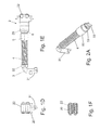
- the Fig. 1A shows a parking lock assembly 1 with a receiving body 3, a mounted on the rear end portion, laterally projecting engagement portion 31 and a bearing at the front end portion by means of a guide member 5 support portion 2.
- the parking lock assembly 1 is between an adjusting mechanism, in particular a manually operated shift lever, and a Parksperrenrad installed to engage in parking position a locking member in the parking lock gear and disengage outside the parking position.
- the receiving body 3 is formed by a longitudinally extending straight rod, at the rear end portion of the engaging portion 31 is rigidly mounted at right angles, in particular bent.
- a helical spring 4 is arranged coaxially, which is supported at its rear end against a fixedly mounted on the receiving body 3 rear abutment 32 and which is supported with its front end portion against the displaceably mounted guide member 5, which against one of the Spring 4 exerted compressive force adjustable to the rear and by means of the pressure force in a front end position is movable, which is determined by a fixed to the front end portion of the receiving body 3 front abutment 33.
- the sleeve-shaped and coaxially mounted on the receiving body 3 slidably guide member 5 abuts in the front end position with its front end against the front abutment 33, as in particular Fig. 1B is apparent.
- the front and the rear abutment 33, 32 can z. B. by means of an embossing of the receiving body 3 integrally formed on this.
- a holding member 20 of the support portion 2 is fixed immovably relative to the guide member 5.
- the holding member 20 is in a plan view (axially to the engaging portion 31) U-shaped and secured with its U-web to the front portion of the guide member 5, while the symmetrical in plan view with respect to the longitudinal axis of the receiving body 3 projecting U-legs between their front Wear end support elements in the form of two roller-like rollers 22 whose axis of rotation is perpendicular to the longitudinal axis of the receiving body 3, as from the Fig. 1B, 1C . 1D and 1E seen.
- the roller-shaped support elements relevant (not shown) coupling members are actuated for engaging and disengaging a locking member in the parking wheel.
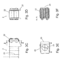
- the front portion 52 of the guide member 5 passes via a shoulder 51 in a rear portion of the guide member 5, which is formed as a in its outer diameter relative to the front portion extended portion 50 and supported against the front portion of the spring 4.
- the front abutment 33 on which the front end face of the guide member 5 is supported, protrudes radially at most to the outer periphery of the front portion 52 of the guide member 5.
- 3A and 3E show, are simply pushed onto the pre-assembled with the guide member 5 and the spring 4 receiving body 3 from the front on the front portion 52 until it reaches a predetermined distance from the engagement portion 31.
- This distance can be accurately adjusted, after which the holding member 20 on the front portion 52 z. B. is fixed in position by welding or gluing.
- the receiving opening 23 is advantageously matched in diameter to the outer diameter of the front sections 52, so that even if the fixation should break by means of the connecting means 6, a support against the shoulder 51 of the guide member 5 is achieved and a support function for actuation of Parking lock is given.
- the receiving body 3, the guide member 5 slidably mounted thereon and the spring 4 are designed as coaxial with each other, cylindrical parts, whereby an exact coordination with each other and reliable operation with a simple structure and ease of assembly are obtained.
Landscapes
- Engineering & Computer Science (AREA)
- General Engineering & Computer Science (AREA)
- Mechanical Engineering (AREA)
- Braking Elements And Transmission Devices (AREA)
- Braking Arrangements (AREA)
- Gear-Shifting Mechanisms (AREA)
Abstract
Die Erfindung bezieht sich auf eine Parksperrenbaueinheit mit einem längserstreckten Aufnahmekörper (3), dessen hinterer Endabschnitt mit einem quer zur Längsachse des Aufnahmekörpers (3) von diesem abstehenden Eingriffabschnitt (31) und dessen vorderer Endabschnitt mit einem endseitig vorstehenden Stützabschnitt (2) versehen ist. Ein für die Herstellung und Funktion vorteilhafter Aufbau wird dadurch erreicht, dass der Eingriffabschnitt (31) starr mit dem Aufnahmekörper (3) verbunden und der Stützabschnitt (2) mittels eines Führungsgliedes (5) begrenzt gegen eine Federkraft verschieblich auf dem Aufnahmekörper (3) gelagert ist (Fig. 1A).The invention relates to a parking brake assembly having an elongated receiving body (3) whose rear end portion is provided with a transversely to the longitudinal axis of the receiving body (3) projecting from this engaging portion (31) and its front end portion with a terminal projecting support portion (2). An advantageous structure for the production and function is achieved in that the engagement portion (31) rigidly connected to the receiving body (3) and the support portion (2) by means of a guide member (5) mounted displaceably against the spring force on the receiving body (3) is (Fig. 1A).
Description
Die Erfindung bezieht sich auf eine Parksperrenbaueinheit mit einem längserstreckten Aufnahmekörper, dessen hinterer Endabschnitt mit einem quer zur Längsachse des Aufnahmekörpers von diesem abstehenden, starr mit dem Aufnahmekörper verbundenen Eingriffabschnitt und dessen vorderer Endabschnitt mit einem endseitig vorstehenden, ein Halteelement aufweisenden Stützabschnitt versehen ist, der mittels eines Führungsgliedes begrenzt gegen die Federkraft einer auf dem Aufnahmekörper angeordneten, sich axial erstreckenden Feder abgestützt und verschieblich auf dem Aufnahmekörper gelagert ist und in seinem vorderen Bereich mindestens ein Stützelement trägt, wobei die Feder mit ihrem hinteren Teil gegen ein an dem Aufnahmekörper fest angebrachtes hinteres Widerlager abgestützt ist.The invention relates to a Parksperrenbaueinheit with an elongate receiving body, the rear end portion is provided with a transversely to the longitudinal axis of the receiving body of this projecting, rigidly connected to the receiving body engaging portion and the front end portion with a terminal projecting, a holding element having support portion by means of a guide member limited against the spring force of an arranged on the receiving body, axially extending spring and slidably mounted on the receiving body and carries in its front region at least one support element, wherein the spring with its rear part against a fixedly attached to the receiving body rear abutment is supported.
Eine derartige Parksperrenbaueinheit dient bei Fahrzeugen mit Automatikgetriebe als mechanische Übertragungseinheit zum Einführen eines Sperrelements in ein Parksperrenrad, wenn der Schalthebel in die Parkposition gebracht wird. Eine Parksperrenbaueinheit der vorstehend genannten Art ist in der
Verschiedene weitere Ausführungen von Parksperren für Automatikgetriebe mit unterschiedlich ausgebildeten Parksperrenbaueinheiten zeigen die
Der vorliegenden Erfindung liegt die Aufgabe zugrunde, eine Parksperrenbaueinheit der eingangs genannten Art bereit zu stellen, die bei möglichst einfachen Fertigungsschritten einen präzisen Aufbau und eine zuverlässige Funktion ergibt.The present invention has for its object to provide a Parksperrenbaueinheit of the type mentioned above, which results in the simplest possible manufacturing steps a precise structure and reliable operation.
Diese Aufgabe wird mit den Merkmalen des Anspruchs 1 gelöst. Hierbei ist vorgesehen, dass das Halteelement in seinem hinteren Bereich fest mit dem Führungsglied verbunden ist, dass das Führungsglied hülsenförmig ausgebildet und gleitend auf dem Aufnahmekörper gelagert ist, wobei es einen Teilbereich des vorderen Endabschnitt des Aufnahmekörpers umgibt und gegen die auf dem Aufnahmekörper angeordnete Feder abgestützt ist, dass das Halteelement mittels einer mit ihrem Innenumfang an einen Außenumfang des Führungsglieds angepassten Aufnahmeöffnung auf das Führungsglied aufgesetzt und positionsgerecht für eine Kopplung an einen Betätigungsmechanismus fixiert ist, wobei das Führungsglied zwei über einen Absatz ineinander übergehende Teilabschnitte aufweist und der hintere Teilabschnitt einen im Außendurchmesser erweiterten Teilabschnitt bildet und der vordere Teilabschnitt einen Gleitabschnitt bildet, auf dem der Stützabschnitt befestigt ist, und dass der erweiterte Teilabschnitt des Führungsglieds an dem vorderen Teil der Feder abgestützt ist.This object is achieved with the features of
Der Stützabschnitt mit dem Führungsglied ergibt vorteilhafte Herstellungsmöglichkeiten für einen präzisen Aufbau und eine zuverlässige Funktion.The support portion with the guide member provides advantageous manufacturing possibilities for a precise construction and a reliable function.
Für den Aufbau und die Funktion ist dabei vorteilhaft, dass das Führungsglied hülsenförmig ausgebildet und gleitend auf dem Aufnahmekörper gelagert ist, wobei es einen Teilbereich des vorderen Endabschnitts umgibt und gegen eine auf dem Aufnahmekörper angeordnete, sich axial erstreckende Feder abgestützt ist, und dass der Stützabschnitt ein Halteelement aufweist, welches in seinem hinteren Bereich fest mit dem Führungsstück verbunden ist und in seinem vorderen Bereich mindestens ein Stützelement trägt, und genaue Justiermöglichkeiten werden dadurch erhalten, dass das Halteelement mittels einer mit ihrem Innenumfang an einen Außenumfang des Führungsglieds angepassten Aufnahmeöffnung auf das Führungsglied aufgesetzt und positionsgerecht für eine Kopplung an einen Betätigungsmechanismus fixiert ist. Mittels der Aufnahmeöffnung lässt sich das Führungsglied in einfacher Weise exakt positionieren und damit die Länge zwischen dem Eingriffabschnitt und dem Stützabschnitt genau justieren.It is advantageous for the structure and the function that the guide member is sleeve-shaped and is mounted slidably on the receiving body, wherein it surrounds a portion of the front end portion and is supported against a arranged on the receiving body, axially extending spring, and that the support portion a holding element which is fixedly connected in its rear region with the guide piece and carries at least one support element in its front region, and precise Justiermöglichkeiten are obtained in that the holding element by means of an adapted with its inner periphery to an outer periphery of the guide member receiving opening on the guide member mounted and fixed in position for coupling to an actuating mechanism. By means of the receiving opening, the guide member can be accurately positioned in a simple manner and thus adjust the length between the engaging portion and the support portion exactly.
Zu einer zuverlässigen Funktion sind ferner die Maßnahmen von Vorteil, dass das Führungsglied zwei über einen Absatz ineinander übergehende Teilabschnitte aufweist, wobei der hintere Teilabschnitt einen im Außendurchmesser erweiterten Teilabschnitt bildet und der vordere Teilabschnitt einen Gleitabschnitt bildet, auf dem der Stützabschnitt befestigt ist. Der Absatz zwischen den beiden Teilabschnitten des Führungsglieds ergibt dabei eine zusätzliche Begrenzung für den Stützabschnitt, der bei Anpassung der Aufnahmeöffnung des Führungsglieds an den kleineren Außendurchmesser des vorderen Teilabschnitts höchstens bis zum Anschlag an den Absatz auf den vorderen Teilabschnitt aufgeschoben werden kann, wodurch eine zusätzliche Sicherung, zum Einrücken eines Sperrglieds in ein Parksperrenrad gegeben ist.For a reliable function, the measures are also advantageous in that the guide member has two subsections which merge into one another via a shoulder, wherein the rear subsection has an outer section widened in the outer diameter forms and the front portion forms a sliding portion on which the support portion is fixed. The heel between the two sections of the guide member results in an additional limitation for the support portion, which can be pushed upon adaptation of the receiving opening of the guide member to the smaller outer diameter of the front portion at most up to the stop on the shoulder on the front portion, creating an additional safeguard , Is given for engaging a locking member in a parking lock gear.
Weitere Vorteile für den Aufbau ergeben sich dadurch, dass der erweitere Teilabschnitt an dem vordere Teil der Feder abgestützt ist, welche mit ihrem hinteren Teil gegen ein an dem Aufnahmekörper fest angebrachtes hinteres Widerlager abgestützt ist.Further advantages for the structure result from the fact that the extended portion is supported on the front part of the spring, which is supported with its rear part against a fixedly attached to the receiving body rear abutment.
Eine für eine exakte Herstellung vorteilhafte Maßnahme besteht des Weiteren darin, dass der Stützabschnitt an dem Führungsglied angeschweißt ist. Eine Alternative zu dieser Befestigung des Stützabschnitts an dem Führungsglied ist z. B. eine Verbindung durch Kleben. Diese Verbindungsweisen lassen eine genaue Längenjustierung der Parksperrenbaueinheit zu.Furthermore, a measure which is advantageous for an exact production consists in the fact that the support section is welded to the guide member. An alternative to this attachment of the support portion to the guide member is z. B. a connection by gluing. These ways of connection allow accurate length adjustment of the parking lock assembly.
Weitere vorteilhafte Maßnahmen für die Herstellung bestehen darin, dass das Halteelement U-förmig mit einem an dem Führungsglied befestigten U-Steg und zwei davon nach vorne abgekanteten U-Schenkeln ausgebildet ist, an deren vorderem Bereich das mindestens eine Stützelement angebracht ist.Further advantageous measures for the production are that the holding element is U-shaped with a guide web attached to the U-web and two thereof bent forward U-legs, at the front of the at least one support element is mounted.
Zu einer vorteilhaften Funktion tragen auch die Maßnahmen bei, dass das mindestens eine Stützelement als mindestens eine Rolle ausgebildet ist, die drehbar an dem Halteelement gelagert ist.For an advantageous function also contribute to the measures that the at least one support element is designed as at least one roller which is rotatably mounted on the holding element.
Zu einem vorteilhaften Aufbau und einer zuverlässigen Funktion tragen auch die Maßnahmen bei, dass das Führungsglied mittels der Federkraft in Ruhelage gegen ein an dem Aufnahmekörper in dessen vorderem Endbereich fest angebrachtes vorderes Widerlager gedrückt ist und entgegen der Federkraft begrenzt zurückschiebbar ist.To an advantageous structure and a reliable function also contribute to the measures that the guide member is pressed by the spring force in rest position against a fixed to the receiving body in the front end portion mounted front abutment and against the spring force is limited zurückschiebbar.
Weitere Vorteile für die Herstellung und Funktion ergeben sich dadurch, dass der Eingriffabschnitt als ein von dem Aufnahmekörper abgebogener Abschnitt ausgebildet ist.Further advantages for the production and function result from the fact that the engagement portion is formed as a bent portion of the receiving body.
Die Erfindung wird nachfolgend anhand von Ausführungsbeispielen unter Bezugnahme auf die Zeichnungen näher erläutert. Es zeigen:
- Fig. 1A bis 1F
- eine zusammengebaute Parksperrenbaueinheit in perspektivischer Ansicht, einem Längsschnitt, einer Draufsicht, einer Seitenansicht, einer Vorderansicht und einer Schnittansicht entlang einer Linie A-A in einem Stützabschnitt,
- Fig. 2A, 2B und 2C
- eine perspektivische Ansicht, eine Seitenansicht und eine Vorderansicht der Parksperrenbaueinheit nach
Fig. 1A bis 1F ohne Stützabschnitt und - Fig. 3A und 3F
- den Stützabschnitt der Parksperrenbaueinheit nach den
Fig. 1A bis 1 F in perspektivischer Ansicht, Draufsicht, seitlicher Ansicht, Vorderansicht, rückseitiger Ansicht und in einer geschnittenen Ansicht entlang einer Linie A-A.
- Fig. 1A to 1F
- an assembled parking brake assembly in perspective view, a longitudinal section, a plan view, a side view, a front view and a sectional view along a line AA in a support portion,
- Figs. 2A, 2B and 2C
- a perspective view, a side view and a front view of the parking brake assembly after
Fig. 1A to 1F without support section and - Figs. 3A and 3F
- the support portion of the parking lock assembly after the
Fig. 1A to 1 F in perspective view, plan view, side view, front view, rear view and in a sectional view along a line AA.
Die
Der Aufnahmekörper 3 ist durch eine sich längs erstreckende gerade Stange gebildet, an dessen hinterem Endabschnitt der Eingriffabschnitt 31 rechtwinklig starr angebracht, insbesondere abgebogen ist. Auf dem Aufnahmekörper 3 ist eine schraubenförmige Feder 4 koaxial angeordnet, die an ihrem hinteren Ende gegen ein fest an dem Aufnahmekörper 3 angebrachten hinteres Widerlager 32 abgestützt ist und die mit ihrem vorderen Endabschnitt gegen das verschieblich gelagerte Führungsglied 5 abgestützt ist, welches gegen eine von der Feder 4 ausgeübte Druckkraft nach hinten verstellbar und mittels der Druckkraft in eine vordere Endlage bewegbar ist, welche durch ein an dem vorderen Endabschnitt des Aufnahmekörpers 3 fest gebrachtes vorderes Widerlager 33 bestimmt ist. Das hülsenförmig ausgebildete und koaxial auf den Aufnahmekörper 3 verschieblich aufgesetzte Führungsglied 5 stößt in der vorderen Endlage mit seiner vorderen Stirnseite gegen das vordere Widerlager 33 an, wie insbesondere aus
An einem vorderen Teilabschnitt des Führungsglieds 5 ist ein Halteelement 20 des Stützabschnitts 2 relativ zu dem Führungsglied 5 unbeweglich fixiert. Das Halteelement 20 ist in Draufsicht (axial zu dem Eingriffabschnitt 31) U-förmig ausgeführt und mit seinem U-Steg an dem vorderen Teilabschnitt des Führungsglieds 5 befestigt, während die in Draufsicht symmetrisch bezüglich der Längsachse des Aufnahmekörpers 3 vorstehenden U-Schenkel zwischen ihren vorderen Endbereichen Stützelemente in Form von zwei walzenartigen Rollen 22 tragen, deren Drehachse rechtwinklig zur Längsachse des Aufnahmekörpers 3 verläuft, wie aus den
Wie aus den
Bei dem gezeigten Ausführungsbeispiel sind der Aufnahmekörper 3, das darauf verschieblich gelagerte Führungsglied 5 und die Feder 4 als koaxial zueinander angeordnete, zylinderförmige Teile ausgeführt, wodurch eine exakte Abstimmung aufeinander und zuverlässige Funktion bei einfachem Aufbau und einfacher Montage erhalten werden.In the embodiment shown, the receiving
Claims (6)
dadurch gekennzeichnet,
dass das Halteelement (20) in seinem hinteren Bereich fest mit dem Führungsglied (5) verbunden ist,
dass das Führungsglied (5) hülsenförmig ausgebildet und gleitend auf dem Aufnahmekörper (3) gelagert ist, wobei es einen Teilbereich des vorderen Endabschnitts des Aufnahmekörpers (3) umgibt und gegen die auf dem Aufnahmekörper (3) angeordnete Feder (4) abgestützt ist,
dass das Halteelement (20) mittels einer mit ihrem Innenumfang an einen Außenumfang des Führungsglieds (5) angepassten Aufnahmeöffnung (23) auf das Führungsglied (5) aufgesetzt und positionsgerecht für eine Kopplung an einen Betätigungsmechanismus fixiert ist, wobei das Führungsglied (5) zwei über einen Absatz (51) ineinander übergehende Teilabschnitte aufweist und der hintere Teilabschnitt einen im Außendurchmesser erweiterten Teilabschnitt (50) bildet und der vordere Teilabschnitt einen Gleitabschnitt (52) bildet, auf dem das Halteelement (20) befestigt ist, und
dass der erweiterte Teilabschnitt (50) des Führungsglieds (5) an dem vorderen Teil der Feder (4) abgestützt ist.Parksperrenbaueinheit with an elongate receiving body (3), the rear end portion with a transversely to the longitudinal axis of the receiving body (3) projecting from this, rigidly connected to the receiving body (3) engaging portion (31) and its front end portion with a terminal projecting, a holding element ( 20) having the support portion (2) is provided, which by means of a guide member (5) limited against the spring force of a on the receiving body (3) arranged, axially extending spring (4) supported and slidably mounted on the receiving body (3) and in at least one support element bears on its front region, wherein the spring (4) is supported with its rear part against a rear abutment (32) fixedly attached to the receiving body (3),
characterized,
in that the holding element (20) is fixedly connected to the guide member (5) in its rear region,
is mounted to the guide member (5) is formed sleeve-shaped and slidably mounted on the retaining body (3), wherein it surrounds a portion of the front end portion of the holding body (3) and against which on the receiving body (3) arranged spring (4) is supported,
in that the holding element (20) is placed on the guide member (5) by means of a receiving opening (23) adapted to an outer circumference of the guide member (5) and fixed in position for coupling to an actuating mechanism, wherein the guide member (5) has two a paragraph (51) into each other merging subsections and the rear portion forms an enlarged outer diameter portion (50) and the front portion forms a sliding portion (52) on which the holding element (20) is attached, and
that the extended portion (50) of the guide member (5) at the front part of the spring (4) is supported.
dadurch gekennzeichnet,
dass das Halteelement (20) an dem Führungsglied (5) angeschweißt ist.Parking brake assembly according to one of the preceding claims,
characterized,
that the holding element (20) on the guide member (5) is welded.
dadurch gekennzeichnet,
dass das Halteelement (20) U-förmig mit einem an dem Führungsglied (5) befestigten U-Steg und zwei davon nach vorne abgekanteten U-Schenkeln ausgebildet ist, an deren vorderem Bereich das mindestens eine Stützelement angebracht ist.Parking brake assembly according to claim 1 or 2,
characterized,
in that the holding element (20) is formed in a U-shaped manner with a U-web fastened to the guide member (5) and two U-legs folded forwards, at the front region of which the at least one support element is attached.
dadurch gekennzeichnet,
dass das mindestens eine Stützelement als mindestens eine Rolle (22) ausgebildet ist, die drehbar an dem Halteelement (20) gelagert ist.Parking brake assembly according to one of the preceding claims,
characterized,
in that the at least one support element is designed as at least one roller (22) which is rotatably mounted on the holding element (20).
dadurch gekennzeichnet,
dass das Führungsglied (5) mittels der Federkraft in Ruhelage gegen ein an dem Aufnahmekörper (3) in dessen vorderem Endbereich fest angebrachtes vorderes Widerlager (33) gedrückt ist und entgegen der Federkraft begrenzt zurückschiebbar ist.Parking brake assembly according to one of the preceding claims,
characterized,
that the guide member (5) by means of the spring force in the rest position against a on the receiving body (3) in the front end portion fixedly mounted front abutment (33) is pressed and limited against the spring force is pushed back.
dadurch gekennzeichnet,
dass der Eingriffabschnitt als ein von dem Aufnahmekörper (3) abgebogener Abschnitt ausgebildet ist.Parking brake assembly according to one of the preceding claims,
characterized,
that the engagement portion is formed as one of the receiving body (3) bent portion.
Applications Claiming Priority (1)
| Application Number | Priority Date | Filing Date | Title |
|---|---|---|---|
| DE102014108866.2A DE102014108866B4 (en) | 2014-06-25 | 2014-06-25 | Parksperrenbaueinheit |
Publications (4)
| Publication Number | Publication Date |
|---|---|
| EP2960552A2 true EP2960552A2 (en) | 2015-12-30 |
| EP2960552A3 EP2960552A3 (en) | 2016-03-09 |
| EP2960552C0 EP2960552C0 (en) | 2025-03-19 |
| EP2960552B1 EP2960552B1 (en) | 2025-03-19 |
Family
ID=53498818
Family Applications (1)
| Application Number | Title | Priority Date | Filing Date |
|---|---|---|---|
| EP15173928.1A Active EP2960552B1 (en) | 2014-06-25 | 2015-06-25 | Park lock unit |
Country Status (2)
| Country | Link |
|---|---|
| EP (1) | EP2960552B1 (en) |
| DE (1) | DE102014108866B4 (en) |
Cited By (3)
| Publication number | Priority date | Publication date | Assignee | Title |
|---|---|---|---|---|
| EP3620690A1 (en) * | 2018-09-07 | 2020-03-11 | DURA Automotive Holdings U.K., Ltd. | Parking lock system for transmission of an automatic, hybrid or electric gearbox of a motor vehicle |
| WO2020086984A1 (en) * | 2018-10-25 | 2020-04-30 | Linamar Corporation | Park lock roller assembly |
| CN111173928A (en) * | 2020-01-22 | 2020-05-19 | 海马汽车有限公司 | A parking lever assembly, a parking actuator and a parking lock assembly |
Families Citing this family (3)
| Publication number | Priority date | Publication date | Assignee | Title |
|---|---|---|---|---|
| DE102016124391B4 (en) | 2016-12-14 | 2018-09-13 | Hugo Benzing Gmbh & Co. Kg | Deflection mechanism for a parking brake and method for producing such |
| DE202017102386U1 (en) | 2017-04-21 | 2018-04-24 | Hugo Benzing Gmbh & Co. Kg | Actuator for a parking brake |
| DE102017122747A1 (en) | 2017-08-16 | 2018-08-16 | Schaeffler Technologies AG & Co. KG | Carriage unit of a parking brake of a motor vehicle and method for producing such |
Citations (8)
| Publication number | Priority date | Publication date | Assignee | Title |
|---|---|---|---|---|
| DE19818752A1 (en) | 1997-05-06 | 1998-11-12 | Steyr Daimler Puch Ag | Vehicle-parking brake with ratchet unit and cog wheel |
| DE69707779T2 (en) | 1996-08-05 | 2002-08-08 | General Motors Corp., Detroit | Actuation for the parking brake on a power transmission |
| DE10144056A1 (en) | 2001-09-07 | 2003-03-27 | Ina Schaeffler Kg | Parking-lock for automatic gear has locking ring on gear shaft, locking holes for pawls, selector lever with rods system holding rollers, and thrust piece |
| DE102007007681A1 (en) | 2007-02-16 | 2008-08-21 | Audi Ag | Vehicle operating i.e. stopping, device, has automatic transmission, and parking lock coupled by external force actuation and actuated by mechanical coupling between actuator and locking unit of parking lock |
| DE102010028281A1 (en) | 2010-04-28 | 2011-11-03 | Zf Friedrichshafen Ag | Parking lock device for motor car-machine gear box, has balance spring supported on counter bearing, where spring path of spring and path of lock pawl are limited by sleeve that is supported on bearing and arranged on connection rod |
| US20120018259A1 (en) | 2010-07-23 | 2012-01-26 | Magna Powertrain Ag & Co Kg | Blocking mechanism |
| DE102010061171A1 (en) | 2010-12-10 | 2012-06-14 | Stiwa Holding Gmbh | Parking lock for e.g. automatic transmission of motor car, has operating device comprising operating member forming wedge-shaped active area for engagement with counter-active surface at latch and formed by non-machining component |
| DE102012012673A1 (en) | 2012-06-23 | 2013-12-24 | Daimler Ag | Drive train device for driving passenger motor car, has locking element fixed at gear housing and positively engaging into parking lock wheel, and drum switch actuator system comprising drum switch for operation of parking lock and gear box |
Family Cites Families (1)
| Publication number | Priority date | Publication date | Assignee | Title |
|---|---|---|---|---|
| DE102005010211B4 (en) * | 2005-03-05 | 2017-06-22 | Zf Friedrichshafen Ag | A parking brake mechanism for a motor vehicle comprising an automatic transmission or an automated manual transmission |
-
2014
- 2014-06-25 DE DE102014108866.2A patent/DE102014108866B4/en active Active
-
2015
- 2015-06-25 EP EP15173928.1A patent/EP2960552B1/en active Active
Patent Citations (8)
| Publication number | Priority date | Publication date | Assignee | Title |
|---|---|---|---|---|
| DE69707779T2 (en) | 1996-08-05 | 2002-08-08 | General Motors Corp., Detroit | Actuation for the parking brake on a power transmission |
| DE19818752A1 (en) | 1997-05-06 | 1998-11-12 | Steyr Daimler Puch Ag | Vehicle-parking brake with ratchet unit and cog wheel |
| DE10144056A1 (en) | 2001-09-07 | 2003-03-27 | Ina Schaeffler Kg | Parking-lock for automatic gear has locking ring on gear shaft, locking holes for pawls, selector lever with rods system holding rollers, and thrust piece |
| DE102007007681A1 (en) | 2007-02-16 | 2008-08-21 | Audi Ag | Vehicle operating i.e. stopping, device, has automatic transmission, and parking lock coupled by external force actuation and actuated by mechanical coupling between actuator and locking unit of parking lock |
| DE102010028281A1 (en) | 2010-04-28 | 2011-11-03 | Zf Friedrichshafen Ag | Parking lock device for motor car-machine gear box, has balance spring supported on counter bearing, where spring path of spring and path of lock pawl are limited by sleeve that is supported on bearing and arranged on connection rod |
| US20120018259A1 (en) | 2010-07-23 | 2012-01-26 | Magna Powertrain Ag & Co Kg | Blocking mechanism |
| DE102010061171A1 (en) | 2010-12-10 | 2012-06-14 | Stiwa Holding Gmbh | Parking lock for e.g. automatic transmission of motor car, has operating device comprising operating member forming wedge-shaped active area for engagement with counter-active surface at latch and formed by non-machining component |
| DE102012012673A1 (en) | 2012-06-23 | 2013-12-24 | Daimler Ag | Drive train device for driving passenger motor car, has locking element fixed at gear housing and positively engaging into parking lock wheel, and drum switch actuator system comprising drum switch for operation of parking lock and gear box |
Cited By (4)
| Publication number | Priority date | Publication date | Assignee | Title |
|---|---|---|---|---|
| EP3620690A1 (en) * | 2018-09-07 | 2020-03-11 | DURA Automotive Holdings U.K., Ltd. | Parking lock system for transmission of an automatic, hybrid or electric gearbox of a motor vehicle |
| WO2020086984A1 (en) * | 2018-10-25 | 2020-04-30 | Linamar Corporation | Park lock roller assembly |
| US11614168B2 (en) | 2018-10-25 | 2023-03-28 | Linamar Corporation | Park lock roller assembly |
| CN111173928A (en) * | 2020-01-22 | 2020-05-19 | 海马汽车有限公司 | A parking lever assembly, a parking actuator and a parking lock assembly |
Also Published As
| Publication number | Publication date |
|---|---|
| EP2960552A3 (en) | 2016-03-09 |
| DE102014108866B4 (en) | 2017-04-06 |
| DE102014108866A1 (en) | 2015-12-31 |
| EP2960552C0 (en) | 2025-03-19 |
| EP2960552B1 (en) | 2025-03-19 |
Similar Documents
| Publication | Publication Date | Title |
|---|---|---|
| DE102014108866B4 (en) | Parksperrenbaueinheit | |
| EP1426633B1 (en) | Fastening system | |
| EP3484719B1 (en) | Caster comprising a running wheel | |
| DE102013014718B4 (en) | Steering column for a vehicle | |
| DE102005000150A1 (en) | Fastener feeding device for power driven tackers | |
| DE68903549T2 (en) | CONTROL DEVICE FOR A LOCKABLE GAS SPRING. | |
| DE19919335A1 (en) | Guide sleeve for rod of vehicle head restraint has locking section fixed on lower end of spring-biased deflection lever mounted axially parallel on outside of sleeve so that locking section is pretensioned against rod | |
| WO1999016624A1 (en) | Manual seal with a self-inking device | |
| EP2816243B1 (en) | Fastening element | |
| DE68903707T2 (en) | ROLLING CURTAIN WITH A BRAKE DEVICE WITH A CYLINDRICAL CAM. | |
| EP1834868B1 (en) | Gear change mechanism with compression spring | |
| DE202017102386U1 (en) | Actuator for a parking brake | |
| DE202015106773U1 (en) | Ejector arrangement for a movable furniture part | |
| DE202004017974U1 (en) | Surgical punch | |
| EP0248101B1 (en) | Mechanism for feeding fasteners mounted on magazine strips to an application tool | |
| DE20007948U1 (en) | Swivel joint with snap coupling | |
| DE202014010484U1 (en) | disc brake | |
| EP1555151B1 (en) | Roller blind for vehicle | |
| DE202020107574U1 (en) | Drive device with a support device | |
| DE2107272C3 (en) | Writing element | |
| EP3141677A1 (en) | Handle for driving a connecting rod liner | |
| DE102011102846A1 (en) | Arrangement of path-wear adjuster for adjustment of friction clutch of motor vehicle, has spring provided for pressing thread of spindle nut on external thread of spindle | |
| EP3107773A1 (en) | Activation device for a parking brake | |
| DE1525364C (en) | ||
| DE3322880C2 (en) | Gear shifting device |
Legal Events
| Date | Code | Title | Description |
|---|---|---|---|
| PUAI | Public reference made under article 153(3) epc to a published international application that has entered the european phase |
Free format text: ORIGINAL CODE: 0009012 |
|
| AK | Designated contracting states |
Kind code of ref document: A2 Designated state(s): AL AT BE BG CH CY CZ DE DK EE ES FI FR GB GR HR HU IE IS IT LI LT LU LV MC MK MT NL NO PL PT RO RS SE SI SK SM TR |
|
| AX | Request for extension of the european patent |
Extension state: BA ME |
|
| PUAL | Search report despatched |
Free format text: ORIGINAL CODE: 0009013 |
|
| AK | Designated contracting states |
Kind code of ref document: A3 Designated state(s): AL AT BE BG CH CY CZ DE DK EE ES FI FR GB GR HR HU IE IS IT LI LT LU LV MC MK MT NL NO PL PT RO RS SE SI SK SM TR |
|
| AX | Request for extension of the european patent |
Extension state: BA ME |
|
| RIC1 | Information provided on ipc code assigned before grant |
Ipc: F16H 63/34 20060101AFI20160203BHEP |
|
| 17P | Request for examination filed |
Effective date: 20160909 |
|
| RBV | Designated contracting states (corrected) |
Designated state(s): AL AT BE BG CH CY CZ DE DK EE ES FI FR GB GR HR HU IE IS IT LI LT LU LV MC MK MT NL NO PL PT RO RS SE SI SK SM TR |
|
| STAA | Information on the status of an ep patent application or granted ep patent |
Free format text: STATUS: EXAMINATION IS IN PROGRESS |
|
| 17Q | First examination report despatched |
Effective date: 20171004 |
|
| GRAP | Despatch of communication of intention to grant a patent |
Free format text: ORIGINAL CODE: EPIDOSNIGR1 |
|
| STAA | Information on the status of an ep patent application or granted ep patent |
Free format text: STATUS: GRANT OF PATENT IS INTENDED |
|
| INTG | Intention to grant announced |
Effective date: 20241028 |
|
| GRAS | Grant fee paid |
Free format text: ORIGINAL CODE: EPIDOSNIGR3 |
|
| GRAA | (expected) grant |
Free format text: ORIGINAL CODE: 0009210 |
|
| STAA | Information on the status of an ep patent application or granted ep patent |
Free format text: STATUS: THE PATENT HAS BEEN GRANTED |
|
| AK | Designated contracting states |
Kind code of ref document: B1 Designated state(s): AL AT BE BG CH CY CZ DE DK EE ES FI FR GB GR HR HU IE IS IT LI LT LU LV MC MK MT NL NO PL PT RO RS SE SI SK SM TR |
|
| REG | Reference to a national code |
Ref country code: GB Ref legal event code: FG4D Free format text: NOT ENGLISH |
|
| REG | Reference to a national code |
Ref country code: CH Ref legal event code: EP |
|
| REG | Reference to a national code |
Ref country code: DE Ref legal event code: R096 Ref document number: 502015017050 Country of ref document: DE |
|
| REG | Reference to a national code |
Ref country code: IE Ref legal event code: FG4D Free format text: LANGUAGE OF EP DOCUMENT: GERMAN |
|
| U01 | Request for unitary effect filed |
Effective date: 20250319 |
|
| U07 | Unitary effect registered |
Designated state(s): AT BE BG DE DK EE FI FR IT LT LU LV MT NL PT RO SE SI Effective date: 20250325 |
|
| PG25 | Lapsed in a contracting state [announced via postgrant information from national office to epo] |
Ref country code: RS Free format text: LAPSE BECAUSE OF FAILURE TO SUBMIT A TRANSLATION OF THE DESCRIPTION OR TO PAY THE FEE WITHIN THE PRESCRIBED TIME-LIMIT Effective date: 20250619 |
|
| PG25 | Lapsed in a contracting state [announced via postgrant information from national office to epo] |
Ref country code: NO Free format text: LAPSE BECAUSE OF FAILURE TO SUBMIT A TRANSLATION OF THE DESCRIPTION OR TO PAY THE FEE WITHIN THE PRESCRIBED TIME-LIMIT Effective date: 20250619 |
|
| PG25 | Lapsed in a contracting state [announced via postgrant information from national office to epo] |
Ref country code: HR Free format text: LAPSE BECAUSE OF FAILURE TO SUBMIT A TRANSLATION OF THE DESCRIPTION OR TO PAY THE FEE WITHIN THE PRESCRIBED TIME-LIMIT Effective date: 20250319 |
|
| PG25 | Lapsed in a contracting state [announced via postgrant information from national office to epo] |
Ref country code: GR Free format text: LAPSE BECAUSE OF FAILURE TO SUBMIT A TRANSLATION OF THE DESCRIPTION OR TO PAY THE FEE WITHIN THE PRESCRIBED TIME-LIMIT Effective date: 20250620 |
|
| U20 | Renewal fee for the european patent with unitary effect paid |
Year of fee payment: 11 Effective date: 20250630 |
|
| PG25 | Lapsed in a contracting state [announced via postgrant information from national office to epo] |
Ref country code: SM Free format text: LAPSE BECAUSE OF FAILURE TO SUBMIT A TRANSLATION OF THE DESCRIPTION OR TO PAY THE FEE WITHIN THE PRESCRIBED TIME-LIMIT Effective date: 20250319 |
|
| PG25 | Lapsed in a contracting state [announced via postgrant information from national office to epo] |
Ref country code: ES Free format text: LAPSE BECAUSE OF FAILURE TO SUBMIT A TRANSLATION OF THE DESCRIPTION OR TO PAY THE FEE WITHIN THE PRESCRIBED TIME-LIMIT Effective date: 20250319 |
|
| PG25 | Lapsed in a contracting state [announced via postgrant information from national office to epo] |
Ref country code: PL Free format text: LAPSE BECAUSE OF FAILURE TO SUBMIT A TRANSLATION OF THE DESCRIPTION OR TO PAY THE FEE WITHIN THE PRESCRIBED TIME-LIMIT Effective date: 20250319 |
|
| PG25 | Lapsed in a contracting state [announced via postgrant information from national office to epo] |
Ref country code: CZ Free format text: LAPSE BECAUSE OF FAILURE TO SUBMIT A TRANSLATION OF THE DESCRIPTION OR TO PAY THE FEE WITHIN THE PRESCRIBED TIME-LIMIT Effective date: 20250319 |
|
| PG25 | Lapsed in a contracting state [announced via postgrant information from national office to epo] |
Ref country code: SK Free format text: LAPSE BECAUSE OF FAILURE TO SUBMIT A TRANSLATION OF THE DESCRIPTION OR TO PAY THE FEE WITHIN THE PRESCRIBED TIME-LIMIT Effective date: 20250319 |
|
| PG25 | Lapsed in a contracting state [announced via postgrant information from national office to epo] |
Ref country code: IS Free format text: LAPSE BECAUSE OF FAILURE TO SUBMIT A TRANSLATION OF THE DESCRIPTION OR TO PAY THE FEE WITHIN THE PRESCRIBED TIME-LIMIT Effective date: 20250719 |
|
| PLBE | No opposition filed within time limit |
Free format text: ORIGINAL CODE: 0009261 |
|
| STAA | Information on the status of an ep patent application or granted ep patent |
Free format text: STATUS: NO OPPOSITION FILED WITHIN TIME LIMIT |
|
| REG | Reference to a national code |
Ref country code: CH Ref legal event code: H13 Free format text: ST27 STATUS EVENT CODE: U-0-0-H10-H13 (AS PROVIDED BY THE NATIONAL OFFICE) Effective date: 20260127 |
|
| REG | Reference to a national code |
Ref country code: CH Ref legal event code: L10 Free format text: ST27 STATUS EVENT CODE: U-0-0-L10-L00 (AS PROVIDED BY THE NATIONAL OFFICE) Effective date: 20260128 |
|
| PG25 | Lapsed in a contracting state [announced via postgrant information from national office to epo] |
Ref country code: MC Free format text: LAPSE BECAUSE OF FAILURE TO SUBMIT A TRANSLATION OF THE DESCRIPTION OR TO PAY THE FEE WITHIN THE PRESCRIBED TIME-LIMIT Effective date: 20250319 |
|
| 26N | No opposition filed |
Effective date: 20251222 |
|
| GBPC | Gb: european patent ceased through non-payment of renewal fee |
Effective date: 20250625 |
|
| PG25 | Lapsed in a contracting state [announced via postgrant information from national office to epo] |
Ref country code: GB Free format text: LAPSE BECAUSE OF NON-PAYMENT OF DUE FEES Effective date: 20250625 |
|
| PG25 | Lapsed in a contracting state [announced via postgrant information from national office to epo] |
Ref country code: IE Free format text: LAPSE BECAUSE OF NON-PAYMENT OF DUE FEES Effective date: 20250625 |