EP2960552A2 - Composant de frein de stationnement - Google Patents
Composant de frein de stationnement Download PDFInfo
- Publication number
- EP2960552A2 EP2960552A2 EP15173928.1A EP15173928A EP2960552A2 EP 2960552 A2 EP2960552 A2 EP 2960552A2 EP 15173928 A EP15173928 A EP 15173928A EP 2960552 A2 EP2960552 A2 EP 2960552A2
- Authority
- EP
- European Patent Office
- Prior art keywords
- guide member
- receiving body
- holding element
- spring
- parking brake
- Prior art date
- Legal status (The legal status is an assumption and is not a legal conclusion. Google has not performed a legal analysis and makes no representation as to the accuracy of the status listed.)
- Granted
Links
Images


Classifications
-
- F—MECHANICAL ENGINEERING; LIGHTING; HEATING; WEAPONS; BLASTING
- F16—ENGINEERING ELEMENTS AND UNITS; GENERAL MEASURES FOR PRODUCING AND MAINTAINING EFFECTIVE FUNCTIONING OF MACHINES OR INSTALLATIONS; THERMAL INSULATION IN GENERAL
- F16H—GEARING
- F16H63/00—Control outputs from the control unit to change-speed- or reversing-gearings for conveying rotary motion or to other devices than the final output mechanism
- F16H63/02—Final output mechanisms therefor; Actuating means for the final output mechanisms
- F16H63/30—Constructional features of the final output mechanisms
- F16H63/34—Locking or disabling mechanisms
- F16H63/3416—Parking lock mechanisms or brakes in the transmission
Definitions
- the invention relates to a Parksperrenbauaji with an elongate receiving body, the rear end portion is provided with a transversely to the longitudinal axis of the receiving body of this projecting, rigidly connected to the receiving body engaging portion and the front end portion with a terminal projecting, a holding element having support portion by means of a guide member limited against the spring force of an arranged on the receiving body, axially extending spring and slidably mounted on the receiving body and carries in its front region at least one support element, wherein the spring with its rear part against a fixedly attached to the receiving body rear abutment is supported.
- Such a parking lock assembly is used in vehicles with automatic transmission as a mechanical transmission unit for introducing a locking element in a parking lock gear when the shift lever is brought into the parking position.
- a parking lock construction unit the type mentioned above is in the DE 697 07 779 T2 specified.
- On a straight, rod-like receiving body is at a front end portion a holding member having a support portion for operating further mechanical coupling members fixedly mounted to move the locking element in the desired position.
- the other end portion of the receiving body is provided with a projecting from the receiving body perpendicular to the longitudinal axis engaging portion.
- the support portion is axially displaceable over a limited way against a spring force on the receiving body, while the engagement portion is coupled via correspondingly formed further elements with the shift lever.
- the present invention has for its object to provide a Parksperrenbauisme of the type mentioned above, which results in the simplest possible manufacturing steps a precise structure and reliable operation.
- the holding element is firmly connected in its rear region with the guide member, that the guide member is sleeve-shaped and slidably mounted on the receiving body, wherein it surrounds a portion of the front end portion of the receiving body and supported against the arranged on the receiving body spring is that the holding element by means of a with its inner circumference adapted to an outer circumference of the guide member receiving opening the guide member is mounted and fixed in position for coupling to an actuating mechanism, wherein the guide member has two paragraphs merging into each other via a paragraph sections and the rear portion forms an enlarged outer diameter portion and the front portion forms a sliding portion on which the support portion is attached, and that the extended portion of the guide member is supported on the front part of the spring.
- the support portion with the guide member provides advantageous manufacturing possibilities for a precise construction and a reliable function.
- the guide member is sleeve-shaped and is mounted slidably on the receiving body, wherein it surrounds a portion of the front end portion and is supported against a arranged on the receiving body, axially extending spring, and that the support portion a holding element which is fixedly connected in its rear region with the guide piece and carries at least one support element in its front region, and precise Justierdes are obtained in that the holding element by means of an adapted with its inner periphery to an outer periphery of the guide member receiving opening on the guide member mounted and fixed in position for coupling to an actuating mechanism.
- the guide member can be accurately positioned in a simple manner and thus adjust the length between the engaging portion and the support portion exactly.
- the measures are also advantageous in that the guide member has two subsections which merge into one another via a shoulder, wherein the rear subsection has an outer section widened in the outer diameter forms and the front portion forms a sliding portion on which the support portion is fixed.
- the heel between the two sections of the guide member results in an additional limitation for the support portion, which can be pushed upon adaptation of the receiving opening of the guide member to the smaller outer diameter of the front portion at most up to the stop on the shoulder on the front portion, creating an additional safeguard , Is given for engaging a locking member in a parking lock gear.
- a measure which is advantageous for an exact production consists in the fact that the support section is welded to the guide member.
- An alternative to this attachment of the support portion to the guide member is z.
- the holding element is U-shaped with a guide web attached to the U-web and two thereof bent forward U-legs, at the front of the at least one support element is mounted.
- the at least one support element is designed as at least one roller which is rotatably mounted on the holding element.
- the engagement portion is formed as a bent portion of the receiving body.
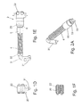
- the Fig. 1A shows a parking lock assembly 1 with a receiving body 3, a mounted on the rear end portion, laterally projecting engagement portion 31 and a bearing at the front end portion by means of a guide member 5 support portion 2.
- the parking lock assembly 1 is between an adjusting mechanism, in particular a manually operated shift lever, and a Parksperrenrad installed to engage in parking position a locking member in the parking lock gear and disengage outside the parking position.
- the receiving body 3 is formed by a longitudinally extending straight rod, at the rear end portion of the engaging portion 31 is rigidly mounted at right angles, in particular bent.
- a helical spring 4 is arranged coaxially, which is supported at its rear end against a fixedly mounted on the receiving body 3 rear abutment 32 and which is supported with its front end portion against the displaceably mounted guide member 5, which against one of the Spring 4 exerted compressive force adjustable to the rear and by means of the pressure force in a front end position is movable, which is determined by a fixed to the front end portion of the receiving body 3 front abutment 33.
- the sleeve-shaped and coaxially mounted on the receiving body 3 slidably guide member 5 abuts in the front end position with its front end against the front abutment 33, as in particular Fig. 1B is apparent.
- the front and the rear abutment 33, 32 can z. B. by means of an embossing of the receiving body 3 integrally formed on this.
- a holding member 20 of the support portion 2 is fixed immovably relative to the guide member 5.
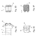
- the holding member 20 is in a plan view (axially to the engaging portion 31) U-shaped and secured with its U-web to the front portion of the guide member 5, while the symmetrical in plan view with respect to the longitudinal axis of the receiving body 3 projecting U-legs between their front Wear end support elements in the form of two roller-like rollers 22 whose axis of rotation is perpendicular to the longitudinal axis of the receiving body 3, as from the Fig. 1B, 1C . 1D and 1E seen.
- the roller-shaped support elements relevant (not shown) coupling members are actuated for engaging and disengaging a locking member in the parking wheel.
- the front portion 52 of the guide member 5 passes via a shoulder 51 in a rear portion of the guide member 5, which is formed as a in its outer diameter relative to the front portion extended portion 50 and supported against the front portion of the spring 4.
- the front abutment 33 on which the front end face of the guide member 5 is supported, protrudes radially at most to the outer periphery of the front portion 52 of the guide member 5.
- 3A and 3E show, are simply pushed onto the pre-assembled with the guide member 5 and the spring 4 receiving body 3 from the front on the front portion 52 until it reaches a predetermined distance from the engagement portion 31.
- This distance can be accurately adjusted, after which the holding member 20 on the front portion 52 z. B. is fixed in position by welding or gluing.
- the receiving opening 23 is advantageously matched in diameter to the outer diameter of the front sections 52, so that even if the fixation should break by means of the connecting means 6, a support against the shoulder 51 of the guide member 5 is achieved and a support function for actuation of Parking lock is given.
- the receiving body 3, the guide member 5 slidably mounted thereon and the spring 4 are designed as coaxial with each other, cylindrical parts, whereby an exact coordination with each other and reliable operation with a simple structure and ease of assembly are obtained.
Landscapes
- Engineering & Computer Science (AREA)
- General Engineering & Computer Science (AREA)
- Mechanical Engineering (AREA)
- Braking Elements And Transmission Devices (AREA)
- Braking Arrangements (AREA)
- Gear-Shifting Mechanisms (AREA)
Applications Claiming Priority (1)
| Application Number | Priority Date | Filing Date | Title |
|---|---|---|---|
| DE102014108866.2A DE102014108866B4 (de) | 2014-06-25 | 2014-06-25 | Parksperrenbaueinheit |
Publications (4)
| Publication Number | Publication Date |
|---|---|
| EP2960552A2 true EP2960552A2 (fr) | 2015-12-30 |
| EP2960552A3 EP2960552A3 (fr) | 2016-03-09 |
| EP2960552B1 EP2960552B1 (fr) | 2025-03-19 |
| EP2960552C0 EP2960552C0 (fr) | 2025-03-19 |
Family
ID=53498818
Family Applications (1)
| Application Number | Title | Priority Date | Filing Date |
|---|---|---|---|
| EP15173928.1A Active EP2960552B1 (fr) | 2014-06-25 | 2015-06-25 | Composant de frein de stationnement |
Country Status (2)
| Country | Link |
|---|---|
| EP (1) | EP2960552B1 (fr) |
| DE (1) | DE102014108866B4 (fr) |
Cited By (3)
| Publication number | Priority date | Publication date | Assignee | Title |
|---|---|---|---|---|
| EP3620690A1 (fr) * | 2018-09-07 | 2020-03-11 | DURA Automotive Holdings U.K., Ltd. | Système de blocage en stationnement pour une transmission d'une boîte de vitesses automatique, hybride, ou électrique d'un véhicule automobile |
| WO2020086984A1 (fr) * | 2018-10-25 | 2020-04-30 | Linamar Corporation | Ensemble rouleau de verrouillage de stationnement |
| CN111173928A (zh) * | 2020-01-22 | 2020-05-19 | 海马汽车有限公司 | 一种驻车拉杆组件、驻车执行机构和驻车锁止总成 |
Families Citing this family (3)
| Publication number | Priority date | Publication date | Assignee | Title |
|---|---|---|---|---|
| DE102016124391B4 (de) | 2016-12-14 | 2018-09-13 | Hugo Benzing Gmbh & Co. Kg | Auslenkmechanismus für eine Parksperre und Verfahren zur Herstellung eines solchen |
| DE202017102386U1 (de) | 2017-04-21 | 2018-04-24 | Hugo Benzing Gmbh & Co. Kg | Betätigungseinheit für eine Parksperre |
| DE102017122747A1 (de) | 2017-08-16 | 2018-08-16 | Schaeffler Technologies AG & Co. KG | Schlitteneinheit einer Parksperre eines Kraftfahrzeugs und Verfahren zum Herstellen einer solchen |
Citations (8)
| Publication number | Priority date | Publication date | Assignee | Title |
|---|---|---|---|---|
| DE19818752A1 (de) | 1997-05-06 | 1998-11-12 | Steyr Daimler Puch Ag | Parksperre für ein Kraftfahrzeug |
| DE69707779T2 (de) | 1996-08-05 | 2002-08-08 | General Motors Corp., Detroit | Betätigung für die Parkbremse an einem Leistungsgetriebe |
| DE10144056A1 (de) | 2001-09-07 | 2003-03-27 | Ina Schaeffler Kg | Parksperre für ein Automatikgetriebe eines Kraftfahrzeuges |
| DE102007007681A1 (de) | 2007-02-16 | 2008-08-21 | Audi Ag | Vorrichtung und Verfahren zum Abstellen eines Fahrzeugs mit einem automatischen Getriebe |
| DE102010028281A1 (de) | 2010-04-28 | 2011-11-03 | Zf Friedrichshafen Ag | Parksperreneinrichtung für ein Kraftfahrzeug-Automatgetriebe |
| US20120018259A1 (en) | 2010-07-23 | 2012-01-26 | Magna Powertrain Ag & Co Kg | Blocking mechanism |
| DE102010061171A1 (de) | 2010-12-10 | 2012-06-14 | Stiwa Holding Gmbh | Parksperre für ein Kraftfahrzeuggetriebe |
| DE102012012673A1 (de) | 2012-06-23 | 2013-12-24 | Daimler Ag | Kraftfahrzeugantriebsstrangvorrichtung mit einer Parksperre |
Family Cites Families (1)
| Publication number | Priority date | Publication date | Assignee | Title |
|---|---|---|---|---|
| DE102005010211B4 (de) * | 2005-03-05 | 2017-06-22 | Zf Friedrichshafen Ag | Parksperrenmechanismus für ein Kraftfahrzeug, welches ein Automatgetriebe oder ein automatisiertes Handschaltgetriebe umfasst |
-
2014
- 2014-06-25 DE DE102014108866.2A patent/DE102014108866B4/de active Active
-
2015
- 2015-06-25 EP EP15173928.1A patent/EP2960552B1/fr active Active
Patent Citations (8)
| Publication number | Priority date | Publication date | Assignee | Title |
|---|---|---|---|---|
| DE69707779T2 (de) | 1996-08-05 | 2002-08-08 | General Motors Corp., Detroit | Betätigung für die Parkbremse an einem Leistungsgetriebe |
| DE19818752A1 (de) | 1997-05-06 | 1998-11-12 | Steyr Daimler Puch Ag | Parksperre für ein Kraftfahrzeug |
| DE10144056A1 (de) | 2001-09-07 | 2003-03-27 | Ina Schaeffler Kg | Parksperre für ein Automatikgetriebe eines Kraftfahrzeuges |
| DE102007007681A1 (de) | 2007-02-16 | 2008-08-21 | Audi Ag | Vorrichtung und Verfahren zum Abstellen eines Fahrzeugs mit einem automatischen Getriebe |
| DE102010028281A1 (de) | 2010-04-28 | 2011-11-03 | Zf Friedrichshafen Ag | Parksperreneinrichtung für ein Kraftfahrzeug-Automatgetriebe |
| US20120018259A1 (en) | 2010-07-23 | 2012-01-26 | Magna Powertrain Ag & Co Kg | Blocking mechanism |
| DE102010061171A1 (de) | 2010-12-10 | 2012-06-14 | Stiwa Holding Gmbh | Parksperre für ein Kraftfahrzeuggetriebe |
| DE102012012673A1 (de) | 2012-06-23 | 2013-12-24 | Daimler Ag | Kraftfahrzeugantriebsstrangvorrichtung mit einer Parksperre |
Cited By (4)
| Publication number | Priority date | Publication date | Assignee | Title |
|---|---|---|---|---|
| EP3620690A1 (fr) * | 2018-09-07 | 2020-03-11 | DURA Automotive Holdings U.K., Ltd. | Système de blocage en stationnement pour une transmission d'une boîte de vitesses automatique, hybride, ou électrique d'un véhicule automobile |
| WO2020086984A1 (fr) * | 2018-10-25 | 2020-04-30 | Linamar Corporation | Ensemble rouleau de verrouillage de stationnement |
| US11614168B2 (en) | 2018-10-25 | 2023-03-28 | Linamar Corporation | Park lock roller assembly |
| CN111173928A (zh) * | 2020-01-22 | 2020-05-19 | 海马汽车有限公司 | 一种驻车拉杆组件、驻车执行机构和驻车锁止总成 |
Also Published As
| Publication number | Publication date |
|---|---|
| EP2960552B1 (fr) | 2025-03-19 |
| EP2960552C0 (fr) | 2025-03-19 |
| EP2960552A3 (fr) | 2016-03-09 |
| DE102014108866A1 (de) | 2015-12-31 |
| DE102014108866B4 (de) | 2017-04-06 |
Similar Documents
| Publication | Publication Date | Title |
|---|---|---|
| DE102014108866B4 (de) | Parksperrenbaueinheit | |
| EP3484719B1 (fr) | Galet de direction muni d'une roue directrice | |
| DE102013014718B4 (de) | Lenksäule für ein Fahrzeug | |
| DE102005000150A1 (de) | Befestigungsmittel-Zuführeinrichtung für kraftbetriebene Eintreibgeräte | |
| DE68903549T2 (de) | Regelvorrichtung fuer eine sperrbare gasfeder. | |
| DE19919335A1 (de) | Führungshülse für die Stange einer Kopfstütze | |
| WO1999016624A1 (fr) | Timbre manuel auto-encreur | |
| EP2816243B1 (fr) | Élément de fixation | |
| DE68903707T2 (de) | Rollvorhang mit einer bremsvorrichtung mit einer zylindrischen nocke. | |
| EP1834868B1 (fr) | Mécanisme de changement de vitesses doté d'un ressort de compression | |
| DE202017102386U1 (de) | Betätigungseinheit für eine Parksperre | |
| DE202015106773U1 (de) | Auswerferanordnung für ein bewegbares Möbelteil | |
| DE202004017974U1 (de) | Chirurgisches Stanzinstrument | |
| EP0248101B1 (fr) | Mécanisme d'alimentation des éléments de fixation montés sur une bande à un outil de pose de tels éléments | |
| DE20007948U1 (de) | Drehgelenk mit Rastkupplung | |
| DE202014010484U1 (de) | Scheibenbremse | |
| EP1555151B1 (fr) | Store à enrouleur pour véhicule | |
| DE202020107574U1 (de) | Antriebsvorrichtung mit einer Stützvorrichtung | |
| DE2107272C3 (de) | Schreibelement | |
| EP3141677A1 (fr) | Systeme de manutention destine a l'entrainement d'une ferrure de bielle | |
| DE102011102846A1 (de) | Anordnung mit einem anzutreibenden Bauteil und einem entsprechenden Spindeltrieb zum Antrieb des Bauteils | |
| EP3107773A1 (fr) | Dispositif d'actionnement pour un frein de stationnement | |
| DE1525364C (fr) | ||
| DE3322880C2 (de) | Zahnrad-Schaltvorrichtung | |
| DE102007002632B4 (de) | Kupplung für eine Wickelwelle eines Springrollos |
Legal Events
| Date | Code | Title | Description |
|---|---|---|---|
| PUAI | Public reference made under article 153(3) epc to a published international application that has entered the european phase |
Free format text: ORIGINAL CODE: 0009012 |
|
| AK | Designated contracting states |
Kind code of ref document: A2 Designated state(s): AL AT BE BG CH CY CZ DE DK EE ES FI FR GB GR HR HU IE IS IT LI LT LU LV MC MK MT NL NO PL PT RO RS SE SI SK SM TR |
|
| AX | Request for extension of the european patent |
Extension state: BA ME |
|
| PUAL | Search report despatched |
Free format text: ORIGINAL CODE: 0009013 |
|
| AK | Designated contracting states |
Kind code of ref document: A3 Designated state(s): AL AT BE BG CH CY CZ DE DK EE ES FI FR GB GR HR HU IE IS IT LI LT LU LV MC MK MT NL NO PL PT RO RS SE SI SK SM TR |
|
| AX | Request for extension of the european patent |
Extension state: BA ME |
|
| RIC1 | Information provided on ipc code assigned before grant |
Ipc: F16H 63/34 20060101AFI20160203BHEP |
|
| 17P | Request for examination filed |
Effective date: 20160909 |
|
| RBV | Designated contracting states (corrected) |
Designated state(s): AL AT BE BG CH CY CZ DE DK EE ES FI FR GB GR HR HU IE IS IT LI LT LU LV MC MK MT NL NO PL PT RO RS SE SI SK SM TR |
|
| STAA | Information on the status of an ep patent application or granted ep patent |
Free format text: STATUS: EXAMINATION IS IN PROGRESS |
|
| 17Q | First examination report despatched |
Effective date: 20171004 |
|
| GRAP | Despatch of communication of intention to grant a patent |
Free format text: ORIGINAL CODE: EPIDOSNIGR1 |
|
| STAA | Information on the status of an ep patent application or granted ep patent |
Free format text: STATUS: GRANT OF PATENT IS INTENDED |
|
| INTG | Intention to grant announced |
Effective date: 20241028 |
|
| GRAS | Grant fee paid |
Free format text: ORIGINAL CODE: EPIDOSNIGR3 |
|
| GRAA | (expected) grant |
Free format text: ORIGINAL CODE: 0009210 |
|
| STAA | Information on the status of an ep patent application or granted ep patent |
Free format text: STATUS: THE PATENT HAS BEEN GRANTED |
|
| AK | Designated contracting states |
Kind code of ref document: B1 Designated state(s): AL AT BE BG CH CY CZ DE DK EE ES FI FR GB GR HR HU IE IS IT LI LT LU LV MC MK MT NL NO PL PT RO RS SE SI SK SM TR |
|
| REG | Reference to a national code |
Ref country code: GB Ref legal event code: FG4D Free format text: NOT ENGLISH |
|
| REG | Reference to a national code |
Ref country code: CH Ref legal event code: EP |
|
| REG | Reference to a national code |
Ref country code: DE Ref legal event code: R096 Ref document number: 502015017050 Country of ref document: DE |
|
| REG | Reference to a national code |
Ref country code: IE Ref legal event code: FG4D Free format text: LANGUAGE OF EP DOCUMENT: GERMAN |
|
| U01 | Request for unitary effect filed |
Effective date: 20250319 |
|
| U07 | Unitary effect registered |
Designated state(s): AT BE BG DE DK EE FI FR IT LT LU LV MT NL PT RO SE SI Effective date: 20250325 |
|
| PG25 | Lapsed in a contracting state [announced via postgrant information from national office to epo] |
Ref country code: RS Free format text: LAPSE BECAUSE OF FAILURE TO SUBMIT A TRANSLATION OF THE DESCRIPTION OR TO PAY THE FEE WITHIN THE PRESCRIBED TIME-LIMIT Effective date: 20250619 |
|
| PG25 | Lapsed in a contracting state [announced via postgrant information from national office to epo] |
Ref country code: NO Free format text: LAPSE BECAUSE OF FAILURE TO SUBMIT A TRANSLATION OF THE DESCRIPTION OR TO PAY THE FEE WITHIN THE PRESCRIBED TIME-LIMIT Effective date: 20250619 |
|
| PG25 | Lapsed in a contracting state [announced via postgrant information from national office to epo] |
Ref country code: HR Free format text: LAPSE BECAUSE OF FAILURE TO SUBMIT A TRANSLATION OF THE DESCRIPTION OR TO PAY THE FEE WITHIN THE PRESCRIBED TIME-LIMIT Effective date: 20250319 |
|
| PG25 | Lapsed in a contracting state [announced via postgrant information from national office to epo] |
Ref country code: GR Free format text: LAPSE BECAUSE OF FAILURE TO SUBMIT A TRANSLATION OF THE DESCRIPTION OR TO PAY THE FEE WITHIN THE PRESCRIBED TIME-LIMIT Effective date: 20250620 |
|
| U20 | Renewal fee for the european patent with unitary effect paid |
Year of fee payment: 11 Effective date: 20250630 |
|
| PG25 | Lapsed in a contracting state [announced via postgrant information from national office to epo] |
Ref country code: SM Free format text: LAPSE BECAUSE OF FAILURE TO SUBMIT A TRANSLATION OF THE DESCRIPTION OR TO PAY THE FEE WITHIN THE PRESCRIBED TIME-LIMIT Effective date: 20250319 |
|
| PG25 | Lapsed in a contracting state [announced via postgrant information from national office to epo] |
Ref country code: ES Free format text: LAPSE BECAUSE OF FAILURE TO SUBMIT A TRANSLATION OF THE DESCRIPTION OR TO PAY THE FEE WITHIN THE PRESCRIBED TIME-LIMIT Effective date: 20250319 |
|
| PG25 | Lapsed in a contracting state [announced via postgrant information from national office to epo] |
Ref country code: PL Free format text: LAPSE BECAUSE OF FAILURE TO SUBMIT A TRANSLATION OF THE DESCRIPTION OR TO PAY THE FEE WITHIN THE PRESCRIBED TIME-LIMIT Effective date: 20250319 |
|
| PG25 | Lapsed in a contracting state [announced via postgrant information from national office to epo] |
Ref country code: CZ Free format text: LAPSE BECAUSE OF FAILURE TO SUBMIT A TRANSLATION OF THE DESCRIPTION OR TO PAY THE FEE WITHIN THE PRESCRIBED TIME-LIMIT Effective date: 20250319 |
|
| PG25 | Lapsed in a contracting state [announced via postgrant information from national office to epo] |
Ref country code: SK Free format text: LAPSE BECAUSE OF FAILURE TO SUBMIT A TRANSLATION OF THE DESCRIPTION OR TO PAY THE FEE WITHIN THE PRESCRIBED TIME-LIMIT Effective date: 20250319 |
|
| PG25 | Lapsed in a contracting state [announced via postgrant information from national office to epo] |
Ref country code: IS Free format text: LAPSE BECAUSE OF FAILURE TO SUBMIT A TRANSLATION OF THE DESCRIPTION OR TO PAY THE FEE WITHIN THE PRESCRIBED TIME-LIMIT Effective date: 20250719 |
|
| PLBE | No opposition filed within time limit |
Free format text: ORIGINAL CODE: 0009261 |
|
| STAA | Information on the status of an ep patent application or granted ep patent |
Free format text: STATUS: NO OPPOSITION FILED WITHIN TIME LIMIT |
|
| REG | Reference to a national code |
Ref country code: CH Ref legal event code: H13 Free format text: ST27 STATUS EVENT CODE: U-0-0-H10-H13 (AS PROVIDED BY THE NATIONAL OFFICE) Effective date: 20260127 |
|
| REG | Reference to a national code |
Ref country code: CH Ref legal event code: L10 Free format text: ST27 STATUS EVENT CODE: U-0-0-L10-L00 (AS PROVIDED BY THE NATIONAL OFFICE) Effective date: 20260128 |
|
| PG25 | Lapsed in a contracting state [announced via postgrant information from national office to epo] |
Ref country code: MC Free format text: LAPSE BECAUSE OF FAILURE TO SUBMIT A TRANSLATION OF THE DESCRIPTION OR TO PAY THE FEE WITHIN THE PRESCRIBED TIME-LIMIT Effective date: 20250319 |
|
| 26N | No opposition filed |
Effective date: 20251222 |
|
| GBPC | Gb: european patent ceased through non-payment of renewal fee |
Effective date: 20250625 |
|
| PG25 | Lapsed in a contracting state [announced via postgrant information from national office to epo] |
Ref country code: GB Free format text: LAPSE BECAUSE OF NON-PAYMENT OF DUE FEES Effective date: 20250625 |
|
| PG25 | Lapsed in a contracting state [announced via postgrant information from national office to epo] |
Ref country code: IE Free format text: LAPSE BECAUSE OF NON-PAYMENT OF DUE FEES Effective date: 20250625 |
|
| PG25 | Lapsed in a contracting state [announced via postgrant information from national office to epo] |
Ref country code: CH Free format text: LAPSE BECAUSE OF NON-PAYMENT OF DUE FEES Effective date: 20250630 |