EP2960725A1 - Schwingungssystem für Uhrwerk mit Ankerhemmung - Google Patents
Schwingungssystem für Uhrwerk mit Ankerhemmung Download PDFInfo
- Publication number
- EP2960725A1 EP2960725A1 EP14173905.2A EP14173905A EP2960725A1 EP 2960725 A1 EP2960725 A1 EP 2960725A1 EP 14173905 A EP14173905 A EP 14173905A EP 2960725 A1 EP2960725 A1 EP 2960725A1
- Authority
- EP
- European Patent Office
- Prior art keywords
- bar
- anchor
- cap
- oscillating system
- movement according
- Prior art date
- Legal status (The legal status is an assumption and is not a legal conclusion. Google has not performed a legal analysis and makes no representation as to the accuracy of the status listed.)
- Withdrawn
Links
- 230000010355 oscillation Effects 0.000 claims description 21
- 239000000463 material Substances 0.000 claims description 13
- 230000008719 thickening Effects 0.000 claims description 10
- 239000000919 ceramic Substances 0.000 claims description 2
- 239000011521 glass Substances 0.000 claims description 2
- 239000002184 metal Substances 0.000 claims description 2
- 229910052751 metal Inorganic materials 0.000 claims description 2
- 150000002739 metals Chemical class 0.000 claims description 2
- 239000010453 quartz Substances 0.000 claims description 2
- VYPSYNLAJGMNEJ-UHFFFAOYSA-N silicon dioxide Inorganic materials O=[Si]=O VYPSYNLAJGMNEJ-UHFFFAOYSA-N 0.000 claims description 2
- 229910052710 silicon Inorganic materials 0.000 claims 1
- 239000010703 silicon Substances 0.000 claims 1
- 239000000835 fiber Substances 0.000 description 6
- 210000003423 ankle Anatomy 0.000 description 4
- 230000007935 neutral effect Effects 0.000 description 4
- 239000013598 vector Substances 0.000 description 4
- 230000008901 benefit Effects 0.000 description 3
- 238000005459 micromachining Methods 0.000 description 3
- 230000008878 coupling Effects 0.000 description 2
- 238000010168 coupling process Methods 0.000 description 2
- 238000005859 coupling reaction Methods 0.000 description 2
- 238000010586 diagram Methods 0.000 description 2
- 238000006073 displacement reaction Methods 0.000 description 2
- 230000001105 regulatory effect Effects 0.000 description 2
- 238000004873 anchoring Methods 0.000 description 1
- 238000005452 bending Methods 0.000 description 1
- 239000011247 coating layer Substances 0.000 description 1
- 229910021419 crystalline silicon Inorganic materials 0.000 description 1
- 230000007423 decrease Effects 0.000 description 1
- 230000000694 effects Effects 0.000 description 1
- 230000005489 elastic deformation Effects 0.000 description 1
- 238000002955 isolation Methods 0.000 description 1
- 238000000034 method Methods 0.000 description 1
- 238000012986 modification Methods 0.000 description 1
- 230000004048 modification Effects 0.000 description 1
- 229910021421 monocrystalline silicon Inorganic materials 0.000 description 1
- 230000035939 shock Effects 0.000 description 1
- 230000001360 synchronised effect Effects 0.000 description 1
Images



Classifications
-
- G—PHYSICS
- G04—HOROLOGY
- G04B—MECHANICALLY-DRIVEN CLOCKS OR WATCHES; MECHANICAL PARTS OF CLOCKS OR WATCHES IN GENERAL; TIME PIECES USING THE POSITION OF THE SUN, MOON OR STARS
- G04B15/00—Escapements
- G04B15/06—Free escapements
- G04B15/08—Lever escapements
-
- G—PHYSICS
- G04—HOROLOGY
- G04B—MECHANICALLY-DRIVEN CLOCKS OR WATCHES; MECHANICAL PARTS OF CLOCKS OR WATCHES IN GENERAL; TIME PIECES USING THE POSITION OF THE SUN, MOON OR STARS
- G04B17/00—Mechanisms for stabilising frequency
- G04B17/04—Oscillators acting by spring tension
- G04B17/045—Oscillators acting by spring tension with oscillating blade springs
-
- G—PHYSICS
- G04—HOROLOGY
- G04B—MECHANICALLY-DRIVEN CLOCKS OR WATCHES; MECHANICAL PARTS OF CLOCKS OR WATCHES IN GENERAL; TIME PIECES USING THE POSITION OF THE SUN, MOON OR STARS
- G04B15/00—Escapements
- G04B15/14—Component parts or constructional details, e.g. construction of the lever or the escape wheel
Definitions
- the present invention relates to an oscillating system for watch movement with anchor escapement, the oscillating system comprising a mechanical resonator comprising at least one flexible bar held by one end, said proximal end, and arranged to oscillate in a plane around a position of balance, the anchor being arranged to pivot about an axis perpendicular to the plane in which the flexible bar is arranged to oscillate, and the other end of the flexible bar, said distal end, carrying first connecting means arranged for s articulate with second joining means integral with the anchor, so that the anchor pivots alternately in concert with the oscillations of the bar.
- the patent document CH 442'153 proposes to realize improved regulator devices which comprise, on the one hand, a mechanical oscillator-regulator, for example a tuning fork mounted on a base, and secondly, an elastic member whose one end is fixed on one base, while the other end has a lift for cooperating with the toothing of the escape wheel of a movement of watchmaking whose speed is regulated by the oscillator-regulator.
- a mechanical oscillator-regulator for example a tuning fork mounted on a base
- an elastic member whose one end is fixed on one base, while the other end has a lift for cooperating with the toothing of the escape wheel of a movement of watchmaking whose speed is regulated by the oscillator-regulator.
- the patent document EP 2 574 994 describes an oscillating system for free escapement clock movement as defined in the introduction.
- the anchor has a fork having two teeth
- the distal end of the flexible bar carries two pegs spaced from each other and arranged to oscillate transversely to the axis of the bar and to cooperate alternately and respectively with the two teeth of the fork so as to rotate the anchor.
- the implementation of this known oscillating system presents certain difficulties. Indeed, to allow the mechanical exhaust to work well, it is necessary that the flexible bar can oscillate with sufficient energy. However, a high oscillation energy implies oscillations of relatively large amplitude and therefore including a relatively high oscillation speed at the ankles.
- An object of the present invention is to overcome the disadvantages of the prior art just mentioned.
- the invention achieves this goal by providing an oscillating system for an escape clock movement.
- anchor which conforms to the definition given in the introduction.
- This oscillating system is further characterized in that the flexible bar carries a rigid cap attached to the distal end, the first connecting means being fixed on the rigid cap at a predetermined location whose position is such that, when the bar is in the equilibrium position, a first segment connecting the determined location to the pivot axis of the anchor and a second segment connecting the determined location to a reference point form between them an angle ⁇ of between 150 ° and 180 °; where said reference point is the center of inertia of a straight section of the bar whose position is determined so that the length of the portion of the bar between the reference point and the distal end is equal to the quotient the value of the arrow at a given moment, when the bar is not in the equilibrium position, on the value at the same time of the derivative of the deformation of the bar
- the reference point of the bar is itself defined according to the invention as the point of the bar for which the length of the portion of the bar between the reference point and the distal end is equal to the quotient of the value of the arrow at a given time, when the bar is not in the equilibrium position, on the value at the same time of the derivative of the deformation of the bar evaluated at the distal end of the bar. It should be noted that the invention is not limited to an oscillating system in which the flexible bar has a particular shape. This is the reason for the distance between the distal end and the reference point of the bar is expressed in the very general terms above.
- the oscillation movement of the rigid cap driven by the flexible bar thus corresponds to an alternating rotational movement around the virtual center.
- the amplitude and speed of the oscillations of a given point of the cap are proportional to a distance separating this given point from the virtual center.
- the distance separating the virtual center of the joint is less than the distance separating the virtual center from the distal end of the flexible bar. It will be understood that under these conditions, the speed of the oscillations at the articulation between the cap and the anchor is advantageously reduced.
- the oscillating system of the invention comprises a mechanical resonator which comprises at least one flexible bar held by one end.
- the second end of the bar is free, and the bar is arranged to oscillate in a plane around an equilibrium position.
- the figure 4 is a schematic diagram illustrating the elastic deformation of a flexible bar recessed.
- the flexible bar of length L is represented by a single line referenced 3.
- Line 3 is the average fiber. It is an imaginary curve passing through the centers of inertia G of all the straight (transversal) sections of the bar (we can specify that the average fiber corresponds to the neutral fiber in the case where the straight sections have a profile symmetrical).
- the dashed line referenced 5 on the figure 4 is the undeformed average line. It will therefore be understood that, when the bar is in its equilibrium position, the curve 3 is superimposed on the average line 5.
- the flexural deformations of the bar can be quantified by a function called "the deformed" ⁇ (x).
- the Deformed ⁇ (x) is defined as the displacement of the center of inertia G of a cross-section located at a distance "x" from the point of embedding of the bar (o ⁇ x ⁇ L). This displacement is measured perpendicularly to the average line 5. Moreover, when the deformations of the bar are weak, the deformed ⁇ (x) is proportional to the force (referenced F) which causes the bending. The value of the deformation at the free end of the bar is called “arrow" (denoted f). Under the same conditions of small deformations, it can also be considered that the straight sections of the bar remain straight and perpendicular to the neutral fiber during the deformation.
- a rigid cap is attached to the free end of the bar.
- the cap moves parallel to the plane of oscillation of the bar integrally with its free end.
- the classical kinematics teaches us that at each instant when the bar oscillates, it is possible to identify an instantaneous center of rotation (CIR) around which the rigid cap is rotating without translation.
- the CIR is the point of the headdress whose speed is zero.
- the theory also teaches us that the CIR is at the intersection between the perpendiculars to the velocity vectors of each point of the cap.
- the figure 1 attached is a schematic plan view of an oscillating system according to a first embodiment of the invention. It is possible to see in the figure a flexible bar 11 secured by one of its ends, called the proximal end, of a fixed support 13. The other end of the bar, called the distal end, bears a rigid cap 15 which is large in size. comparison with the flexible bar.
- the bar 11, the support 13 and the cap 15 are made of material and extend in the same plane.
- These three elements are preferably made by micromachining of a crystalline silicon wafer. It will be understood, however, that these elements do not necessarily come from material according to the invention, and that in general, these elements could be made of any other suitable material known to those skilled in the art. For example quartz, glass, ceramics or amorphous metals. In addition, the skilled person could use a method other than micromachining.
- the cap 15 has a shape that is almost symmetrical with respect to the axis of the undeformed bar. In addition, the cap is almost double the length of the bar 11. It can be seen in the cap a head portion 15a which extends in the extension of the bar and two side portions 15b and 15c which extend back symmetrically. on either side of the axis of the bar.
- the shape of the cap 15 is preferably chosen so that its center of inertia is in the immediate vicinity of the distal end of the bar 11.
- an escape wheel 18 which cooperates with an anchor 17 mounted on a pivot 19.
- the anchor 17 is provided with a rod 21 which ends with a fork 23.
- the side part 15c of the cap wears a peg 25 arranged to cooperate with the fork 23.
- the peg and the fork constitute the first and the second joining means according to the invention.
- the pin and the fork are arranged to cooperate to form an articulation connecting the cap 15 to the anchor 17.
- the pivot 19 of the anchor and the articulation between the ankle and the fork are on the same line which is perpendicular to the bar 11 in its rest position.
- the figure 1 is a plan view. It will thus be understood that in the absence of information concerning the elevation of the elements shown, the anchor 17 and the flexible bar 11 may be located, or together in the plane of oscillation of the bar (the plane of the sheet of the drawing of the figure 1 ), or at different heights. However, even in the second alternative, the articulation is contained in the rod plane which is a plane perpendicular to the plane in which the rod oscillates (perpendicular to the drawing sheet). Whatever the variant of the embodiment of the figure 1 the rod plane is perpendicular to the axis of the bar 11 in the rest position, and the trace of the rod plane on the plane of the sheet is a line perpendicular to the bar.
- the figure 2 is a schematic plan view of an oscillating system according to a second embodiment of the invention.
- the elements that are common to the oscillating systems according to the first and second embodiments are designated by the same reference numerals on the figure 2 and on the figure 1 .
- the cap 115 does not have exactly the same shape as the cap 15. It is nevertheless verified that the distance between the virtual center (the reference point 27) and the articulation is the same on the figure 2 that on the figure 1 .
- the rod plane containing the pivot 19 and the joint intersects the axis of the bar 11 at the location of the reference point 27 obliquely (with an angle of about 45 ° in the illustrated example).
- the figure 3 is a schematic plan view of an oscillating system according to a third embodiment of the invention.
- the mechanical resonator is constituted by a tuning fork referenced 10.
- the tuning fork comprises two parallel bars 11a and 11b which are connected by one of their ends, called the proximal end, to a bar cross link 12.
- the connecting bar is itself connected in the middle to a fixed support 13.
- Each of the two bars carries a cap (referenced 15) which is identical to the cap illustrated in FIG. figure 1 .
- one of the two caps (the one on the right in the illustrated variant) is connected via an ankle 25 and a fork 23 to the anchor 17.
- each bar 11a, 11b can be considered in isolation to determine the resonance frequency.
- a benefit associated with the symmetry of the tuning fork 10 is that it favors some well-defined vibration modes having a high quality factor.
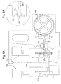
- the Figure 5A is a more detailed plan representation of an oscillating system according to a fourth embodiment of the invention.
- the mechanical resonator is constituted by a tuning fork (referenced 110).
- the tuning fork 110 comprises two parallel bars 111a and 111b of constant section and which are connected to each other by a connecting bar 112 which extends transversely between the proximal ends of the two bars.
- the connecting bar 112 is itself connected in the middle to a fixing arm 113.
- the distal end of the bar 111 has a cap 114, and that of the bar 111 b carries a cap 116. It can be seen in the figure that the caps are large in comparison with the bars of the tuning fork.
- the whole formed by the tuning fork 110 and the caps 114 and 116 has an axis of symmetry which, in the example shown, coincides with the attachment arm 113.
- the caps 114 and 116 are designed so that their center of inertia is at immediate proximity of the distal end of the bar (respectively 111a and 111b) to which they are attached.
- the tuning fork 110, the attachment arm 113 and the caps 114 and 116 are made of material and extend in the same plane. These four elements are preferably made by micromachining a monocrystalline silicon wafer.
- an escape wheel 118 with 90 teeth cooperates with an anchor 117 mounted on a pivot 119.
- the anchor 117 is provided with a rod 121 which ends with an apple 123.
- the cap 114 (the one on the right ) has a notch 125 arranged to receive the apple 123.
- the notch and the apple are shown in more detail in the Figure 5B .
- the notch and the apple cooperate to form an articulation connecting the cap 114 to the anchor 117.
- the articulation between the apple and the notch preferably has a certain clearance.
- the apple could have a diameter of 200 ⁇ m and the width of the notch could be 240 ⁇ m.
- the first and second joining means according to the invention could be designed to be coupled magnetically or electrostatically to each other (possibly even without any mechanical contact).
- the distance between the virtual center (or equivalently the reference point 27) and the articulation corresponds approximately to 2/5 of the distance between the virtual center and the distal end of the bar 111 a.
- the amplitude and the speed of the oscillations at the joint correspond to about 40% of the amplitude and the speed of the oscillations of the distal end of the bar 111a.
- the escape wheel 118 shown on the figure 5 has 90 teeth, which corresponds to an unusually high number of teeth.
- a high number of teeth is an advantageous characteristic.
- the tuning fork 110 is designed to oscillate with a frequency considerably higher than that of a balance-spring resonator. For example, if the tuning fork oscillates at the frequency of 90 Hz, it follows that the illustrated escapement wheel advances at the speed of one revolution per second. This speed is already considerably higher than that of the exhaust wheel of a classic watch. If the escape wheel 118 had half the teeth, it would run twice as fast.
- the figure 6 annexed is a schematic plan view of an oscillating system according to a fifth embodiment of the invention.
- This oscillating system is very similar to the first embodiment illustrated by the figure 1 .
- the oscillating system of the figure 6 according to the invention it can be described as "non-optimal". Indeed, it can be verified that if a straight line is drawn in the drawing which passes through both the pivot 19 and the articulation between the first and the second joining means 23 and 25, this line intersects the bar flexible in a certain distance from the reference point 27.
- the segment connecting the hinge to the reference point 27 is not exactly in the extension of the segment connecting the pivot 19 to the joint .
- the joint Since the joint is not located on the segment that connects the pivot 19 to the virtual center, it follows that the segment connecting the articulation to the pivot axis 19 forms an angle with the segment connecting the articulation to the point of rotation. 27. Note however that according to the invention, the angle ⁇ between the segment connecting the joint to the pivot axis 19 and the segment connecting the joint to the reference point 27 can not be less than 150 °. The angle ⁇ is therefore between 150 and 180 °.
- the figure 7 is a detailed plan representation of an alternative variant of the oscillating system illustrated in FIG. Figure 5A .
- the elements that are common to the oscillating systems according to the two illustrated variants of the fourth embodiment are designated by the same reference numerals on the figure 7 and on the Figure 5A .
- the caps 214 and 216 are not identical to the caps 114 and 116.
- the caps 214 and 216 each have a thickening (respectively referenced 220 and 222) located in the immediate vicinity of the distal end of one of the flexible bars 111a, 111b.
- the thickenings 220 and 222 make it possible to increase the mass of inertia of the caps 214 and 216 without unduly increasing the moment of inertia of the caps relative to their point of attachment on the distal end.
- the caps are arranged in the plane in which the flexible bars 111a and 111b are arranged to oscillate, and each of the caps has two thickenings arranged symmetrically on its two main faces on either side of the plane in which the flexible bars 111a and 111b are arranged to oscillate.
- the thickenings 220, 222 are preferably formed of a denser material than the material of the cap 214, 216 and the bar 111a, 111b. In the illustrated example, these thickenings are in the form of coating layers. However, these thickenings could as well be in the form of inserts for example. It will be further understood that the thickenings could be formed of the same material as the caps.
- a flexible anchor comprises one or more anchoring points integral with a fixed support, and further comprises flexible portions which give it mobility relative to said fixed support.
- a flexible anchor is arranged to pivot about an axis (it will be understood that even if it is not precisely the entire structure of the anchor which pivots about an axis, the anchor proper, or in other words, its part intended to cooperate with the escape wheel, necessarily pivots about an axis). This is called a “virtual pivot”. It will therefore be understood that according to certain embodiments, the pivot axis according to the invention may correspond to a virtual pivot.
Landscapes
- Physics & Mathematics (AREA)
- General Physics & Mathematics (AREA)
- Micromachines (AREA)
Priority Applications (3)
| Application Number | Priority Date | Filing Date | Title |
|---|---|---|---|
| CH00963/14A CH709811B1 (fr) | 2014-06-25 | 2014-06-25 | Système oscillant pour mouvement horloger à échappement à ancre. |
| EP14173905.2A EP2960725A1 (de) | 2014-06-25 | 2014-06-25 | Schwingungssystem für Uhrwerk mit Ankerhemmung |
| PCT/EP2015/063329 WO2015197411A1 (fr) | 2014-06-25 | 2015-06-15 | Systeme oscillant pour mouvement horloger a echappement a ancre |
Applications Claiming Priority (1)
| Application Number | Priority Date | Filing Date | Title |
|---|---|---|---|
| EP14173905.2A EP2960725A1 (de) | 2014-06-25 | 2014-06-25 | Schwingungssystem für Uhrwerk mit Ankerhemmung |
Publications (1)
| Publication Number | Publication Date |
|---|---|
| EP2960725A1 true EP2960725A1 (de) | 2015-12-30 |
Family
ID=50980980
Family Applications (1)
| Application Number | Title | Priority Date | Filing Date |
|---|---|---|---|
| EP14173905.2A Withdrawn EP2960725A1 (de) | 2014-06-25 | 2014-06-25 | Schwingungssystem für Uhrwerk mit Ankerhemmung |
Country Status (3)
| Country | Link |
|---|---|
| EP (1) | EP2960725A1 (de) |
| CH (1) | CH709811B1 (de) |
| WO (1) | WO2015197411A1 (de) |
Families Citing this family (2)
| Publication number | Priority date | Publication date | Assignee | Title |
|---|---|---|---|---|
| EP3032351A1 (de) * | 2014-12-09 | 2016-06-15 | LVMH Swiss Manufactures SA | Uhrmechanismus, Uhrwerk und Uhr mit solch einem Mechanismus |
| EP3812843B1 (de) | 2019-10-25 | 2025-04-23 | ETA SA Manufacture Horlogère Suisse | Flexible führung und gesamtheit von übereinander angeordneten flexiblen führungen für sich drehenden resonatormechanismus, insbesondere für uhrwerk |
Citations (4)
| Publication number | Priority date | Publication date | Assignee | Title |
|---|---|---|---|---|
| CH442153A (fr) | 1965-08-13 | 1967-03-31 | Golay Bernard Sa | Mouvement d'horlogerie |
| FR1505656A (fr) * | 1965-12-07 | 1967-12-15 | Golay Bernard Sa | Dispositif d'échappement |
| EP2574994A1 (de) | 2011-09-29 | 2013-04-03 | Asgalium Unitec SA | Stimmgabelresonator für ein mechanisches Uhrwerk |
| CH705967A1 (fr) * | 2012-01-09 | 2013-07-15 | Lvmh Swiss Mft Sa | Organe réglant pour montre ou chronographe. |
-
2014
- 2014-06-25 EP EP14173905.2A patent/EP2960725A1/de not_active Withdrawn
- 2014-06-25 CH CH00963/14A patent/CH709811B1/fr not_active IP Right Cessation
-
2015
- 2015-06-15 WO PCT/EP2015/063329 patent/WO2015197411A1/fr not_active Ceased
Patent Citations (4)
| Publication number | Priority date | Publication date | Assignee | Title |
|---|---|---|---|---|
| CH442153A (fr) | 1965-08-13 | 1967-03-31 | Golay Bernard Sa | Mouvement d'horlogerie |
| FR1505656A (fr) * | 1965-12-07 | 1967-12-15 | Golay Bernard Sa | Dispositif d'échappement |
| EP2574994A1 (de) | 2011-09-29 | 2013-04-03 | Asgalium Unitec SA | Stimmgabelresonator für ein mechanisches Uhrwerk |
| CH705967A1 (fr) * | 2012-01-09 | 2013-07-15 | Lvmh Swiss Mft Sa | Organe réglant pour montre ou chronographe. |
Also Published As
| Publication number | Publication date |
|---|---|
| WO2015197411A1 (fr) | 2015-12-30 |
| CH709811B1 (fr) | 2018-03-15 |
| CH709811A2 (fr) | 2015-12-31 |
Similar Documents
| Publication | Publication Date | Title |
|---|---|---|
| EP3054358B1 (de) | Oszillatormechanismus für uhr | |
| EP2105806B1 (de) | Hemmungsmechanismus | |
| EP3548973B1 (de) | Vorrichtung für uhren, uhrmechanismus und uhr mit einer solchen vorrichtung. | |
| EP4009115A1 (de) | Spiralfeder für resonatormechanismus eines uhrwerks, der mit mitteln zum ausgleichen der starrheit ausgestattet ist | |
| EP2405313B1 (de) | Spiralfeder mit unbeweglichem Massenzentrum | |
| EP2995999B1 (de) | Synchronisierung der resonatoren eines uhrwerks | |
| EP2790068B1 (de) | Hemmungssystem für einen Spiralunruh-Schwinger | |
| EP3254158A1 (de) | Isochroner zeitmesserresonator | |
| EP4224257A1 (de) | Monolithische spiralfeder-spiralrolle-anordnung | |
| EP2706416A1 (de) | Flexibler Anker mit konstanter Kraft | |
| EP2613206A1 (de) | Spirale mit zwei Spiralfedern mit verbessertem Isochronismus | |
| EP3382470B1 (de) | Oszillator einer uhr mit flexiblem zapfen | |
| EP3206091B1 (de) | Isochroner resonator für eine uhr | |
| CH718113B1 (fr) | Ressort-spiral pour mécanisme résonateur d'horlogerie muni de moyens d'ajustement de la rigidité | |
| EP2960725A1 (de) | Schwingungssystem für Uhrwerk mit Ankerhemmung | |
| EP3336613B1 (de) | Resonator für uhr, der zwei pendellager umfasst, die so angeordnet sind, dass sie auf derselben ebene schwingen können | |
| EP3451073B1 (de) | Uhrwerkoszillator mit flexiblen führungen mit grosser winkelförmiger laufbahn | |
| CH713790B1 (fr) | Mécanisme pour pièce d'horlogerie, mouvement horloger et pièce d'horlogerie comprenant un tel mécanisme. | |
| CH714030A2 (fr) | Oscillateur d'horlogerie à guidages flexibles à grande course angulaire. | |
| FR3140621A1 (fr) | Dispositif micro-électromécanique | |
| EP3572885B1 (de) | Mechanischer oszillator eines isochronen uhrwerks in jeder position | |
| CH720388A2 (fr) | Résonateur piézoélectrique, moteur piézoélectrique et pièce d'horlogerie | |
| EP3561604A1 (de) | Uhrreglermechanismus mit über gelenke verbundenen resonatoren | |
| EP4391347A1 (de) | Piezoelektrischer resonator mit flexibler führung, insbesondere für rotationsmotoren von uhrwerken | |
| CH713791B1 (fr) | Micro mécanisme à réglage de position, mouvement horloger et pièce d'horlogerie comprenant un tel mécanisme. |
Legal Events
| Date | Code | Title | Description |
|---|---|---|---|
| PUAI | Public reference made under article 153(3) epc to a published international application that has entered the european phase |
Free format text: ORIGINAL CODE: 0009012 |
|
| AK | Designated contracting states |
Kind code of ref document: A1 Designated state(s): AL AT BE BG CH CY CZ DE DK EE ES FI FR GB GR HR HU IE IS IT LI LT LU LV MC MK MT NL NO PL PT RO RS SE SI SK SM TR |
|
| AX | Request for extension of the european patent |
Extension state: BA ME |
|
| 17P | Request for examination filed |
Effective date: 20160630 |
|
| RBV | Designated contracting states (corrected) |
Designated state(s): AL AT BE BG CH CY CZ DE DK EE ES FI FR GB GR HR HU IE IS IT LI LT LU LV MC MK MT NL NO PL PT RO RS SE SI SK SM TR |
|
| GRAP | Despatch of communication of intention to grant a patent |
Free format text: ORIGINAL CODE: EPIDOSNIGR1 |
|
| INTG | Intention to grant announced |
Effective date: 20161109 |
|
| STAA | Information on the status of an ep patent application or granted ep patent |
Free format text: STATUS: THE APPLICATION IS DEEMED TO BE WITHDRAWN |
|
| 18D | Application deemed to be withdrawn |
Effective date: 20170321 |