EP4391347A1 - Piezoelektrischer resonator mit flexibler führung, insbesondere für rotationsmotoren von uhrwerken - Google Patents
Piezoelektrischer resonator mit flexibler führung, insbesondere für rotationsmotoren von uhrwerken Download PDFInfo
- Publication number
- EP4391347A1 EP4391347A1 EP22216410.5A EP22216410A EP4391347A1 EP 4391347 A1 EP4391347 A1 EP 4391347A1 EP 22216410 A EP22216410 A EP 22216410A EP 4391347 A1 EP4391347 A1 EP 4391347A1
- Authority
- EP
- European Patent Office
- Prior art keywords
- flexible blade
- oscillating mass
- piezoelectric
- piezoelectric resonator
- flexible
- Prior art date
- Legal status (The legal status is an assumption and is not a legal conclusion. Google has not performed a legal analysis and makes no representation as to the accuracy of the status listed.)
- Pending
Links
Images


Classifications
-
- H—ELECTRICITY
- H02—GENERATION; CONVERSION OR DISTRIBUTION OF ELECTRIC POWER
- H02N—ELECTRIC MACHINES NOT OTHERWISE PROVIDED FOR
- H02N2/00—Electric machines in general using piezoelectric effect, electrostriction or magnetostriction
- H02N2/10—Electric machines in general using piezoelectric effect, electrostriction or magnetostriction producing rotary motion, e.g. rotary motors
- H02N2/101—Electric machines in general using piezoelectric effect, electrostriction or magnetostriction producing rotary motion, e.g. rotary motors using intermittent driving, e.g. step motors
-
- H—ELECTRICITY
- H03—ELECTRONIC CIRCUITRY
- H03H—IMPEDANCE NETWORKS, e.g. RESONANT CIRCUITS; RESONATORS
- H03H9/00—Networks comprising electromechanical or electro-acoustic elements; Electromechanical resonators
- H03H9/15—Constructional features of resonators consisting of piezoelectric or electrostrictive material
-
- F—MECHANICAL ENGINEERING; LIGHTING; HEATING; WEAPONS; BLASTING
- F16—ENGINEERING ELEMENTS AND UNITS; GENERAL MEASURES FOR PRODUCING AND MAINTAINING EFFECTIVE FUNCTIONING OF MACHINES OR INSTALLATIONS; THERMAL INSULATION IN GENERAL
- F16C—SHAFTS; FLEXIBLE SHAFTS; ELEMENTS OR CRANKSHAFT MECHANISMS; ROTARY BODIES OTHER THAN GEARING ELEMENTS; BEARINGS
- F16C11/00—Pivots; Pivotal connections
- F16C11/04—Pivotal connections
- F16C11/12—Pivotal connections incorporating flexible connections, e.g. leaf springs
-
- G—PHYSICS
- G04—HOROLOGY
- G04C—ELECTROMECHANICAL CLOCKS OR WATCHES
- G04C3/00—Electromechanical clocks or watches independent of other time-pieces and in which the movement is maintained by electric means
- G04C3/08—Electromechanical clocks or watches independent of other time-pieces and in which the movement is maintained by electric means wherein movement is regulated by a mechanical oscillator other than a pendulum or balance, e.g. by a tuning fork, e.g. electrostatically
- G04C3/12—Electromechanical clocks or watches independent of other time-pieces and in which the movement is maintained by electric means wherein movement is regulated by a mechanical oscillator other than a pendulum or balance, e.g. by a tuning fork, e.g. electrostatically driven by piezoelectric means; driven by magneto-strictive means
-
- H—ELECTRICITY
- H02—GENERATION; CONVERSION OR DISTRIBUTION OF ELECTRIC POWER
- H02N—ELECTRIC MACHINES NOT OTHERWISE PROVIDED FOR
- H02N2/00—Electric machines in general using piezoelectric effect, electrostriction or magnetostriction
- H02N2/0005—Electric machines in general using piezoelectric effect, electrostriction or magnetostriction producing non-specific motion; Details common to machines covered by H02N2/02 - H02N2/16
- H02N2/001—Driving devices, e.g. vibrators
-
- H—ELECTRICITY
- H02—GENERATION; CONVERSION OR DISTRIBUTION OF ELECTRIC POWER
- H02N—ELECTRIC MACHINES NOT OTHERWISE PROVIDED FOR
- H02N2/00—Electric machines in general using piezoelectric effect, electrostriction or magnetostriction
- H02N2/02—Electric machines in general using piezoelectric effect, electrostriction or magnetostriction producing linear motion, e.g. actuators; Linear positioners ; Linear motors
- H02N2/04—Constructional details
- H02N2/043—Mechanical transmission means, e.g. for stroke amplification
- H02N2/046—Mechanical transmission means, e.g. for stroke amplification for conversion into rotary motion
-
- H—ELECTRICITY
- H02—GENERATION; CONVERSION OR DISTRIBUTION OF ELECTRIC POWER
- H02N—ELECTRIC MACHINES NOT OTHERWISE PROVIDED FOR
- H02N2/00—Electric machines in general using piezoelectric effect, electrostriction or magnetostriction
- H02N2/10—Electric machines in general using piezoelectric effect, electrostriction or magnetostriction producing rotary motion, e.g. rotary motors
- H02N2/12—Constructional details
- H02N2/123—Mechanical transmission means, e.g. for gearing
Definitions
- the invention relates to the technical field of piezoelectric resonators, in particular for rotary piezoelectric motors.
- the invention also relates to the technical field of timepieces equipped with such a rotary piezoelectric motor.
- the electric motors usually used in watchmaking are “Lavet” type rotary motors, which operate on electromagnetic physical principles.
- Such a motor generally comprises a stator equipped with coils and a magnetized rotor, which rotates by out-of-phase actuation of the coils.
- motors have limited resistance to high magnetic fields. From a certain magnetic field value, the motor blocks. In general, they block under the effect of a magnetic field that exceeds 2 mT.
- electrostatic comb motors such as that described in the patent CH709512 . But the combs take up space, and they consume more energy than “Lavet” type motors.
- the aim of the present invention is to provide a piezoelectric resonator, in particular for a rotary piezoelectric motor, which can withstand high electromagnetic fields, while keeping energy consumption and volume reduced.
- the invention relates to a piezoelectric resonator, in particular for a rotary piezoelectric motor of a timepiece, the resonator comprising a stationary base and an oscillating mass extending around a longitudinal axis, the oscillating mass being provided with at least one weight, preferably two opposite weights.
- the invention is remarkable in that it comprises a guide with flexible blades connecting the oscillating mass to the base, so as to be able to make the oscillating mass oscillate around a center of rotation in a pendulum movement, the guidance flexible comprising at least a first flexible blade connecting the base to the oscillating mass, the first flexible blade comprising at least in part an electrically actuable piezoelectric material to deform the first flexible blade and cause the oscillating mass to oscillate.
- a resonator having such a configuration makes it possible to provide movement efficiently.
- they bend, so that the oscillating mass oscillates by pivoting on itself around a center of rotation.
- the resonator produces an oscillatory movement of the oscillating mass, while consuming little energy, because the actuation of the flexible blade(s) requires less energy.
- the resonator piezoelectric By choosing resonance conditions of the resonator at the natural frequency of the resonator, the resonator piezoelectric, and therefore the motor consumes little energy. Actuation at resonance allows for greater amplitude with little energy.
- the oscillatory movement can thus be transmitted to other mechanical parts depending on the field of application of the piezoelectric resonator, for example to a toothed wheel of a movement.
- the center of rotation is arranged substantially in the middle of the oscillating mass, preferably at the center of mass of the oscillating mass.
- the flexible guide comprises a second flexible blade connecting the oscillating mass to the base or to a fixed support.
- the second flexible blade comprises at least in part a piezoelectric material electrically actuable to deform the second flexible blade and cause the oscillating mass to oscillate.
- the first flexible blade and the second flexible blade form an angle of between 30° and 150°, preferably between 60° and 130°, or even between 90° and 120°.
- the first flexible blade and the second flexible blade are uncrossed and move away from a central part of the oscillating mass to eccentric parts of the base.
- the resonator comprises a third flexible blade, the second flexible blade and the third flexible blade being uncrossed and moving apart from a central part of the oscillating mass to eccentric parts of the base.
- the second flexible blade and the third flexible blade form an angle of between 30° and 150°, preferably between 60° and 130°, or even between 90° and 120°.
- the first flexible blade is arranged between the second flexible blade and the third flexible blade.
- the first flexible blade is closer to the second flexible blade than to the third flexible blade.
- the first flexible blade comprises a rigid portion.
- the oscillating mass comprises a weight folded into the shape of an elbow.
- the first flexible blade is oblique and connected to the end of the weight folded into an elbow shape.
- the second flexible blade is substantially parallel to the longitudinal axis of the oscillating mass, and is connected to the inside of the elbow of the flyweight.
- the first flexible blade and the second flexible blade form an angle of between 10 and 90°, preferably between 30° and 60°.
- the first flexible blade has a U shape, and is connected to a weight of the oscillating mass.
- the first flexible blade is arranged parallel to the longitudinal axis of the oscillating mass.
- the second flexible blade is arranged on a side opposite the first flexible blade relative to the oscillating mass.
- the piezoelectric resonator is arranged substantially in the same plane.
- the resonator is configured to oscillate the mass at the natural frequency of the resonator.
- the resonator comprises, preferably predominantly, a mono-crystalline or poly-crystalline material which is non-magnetic and has low conductivity, such as silicon, glass, ceramic, or a metal, and is obtained for example by a photo-lithographic micro-machining process of the MEMS type.
- the flexible guide is in one piece.
- the invention also relates to a piezoelectric motor, in particular for a display device for a timepiece, comprising such a piezoelectric resonator.
- the piezoelectric motor comprises at least one pawl, preferably two pawls, and a movable wheel, the pawl being mounted on the oscillating mass of the piezoelectric resonator, so as to rotate the movable wheel in a first sense, when the oscillating mass carries out its oscillations.
- the invention also relates to a timepiece comprising a timepiece movement comprising a gear transmission configured to rotate at least one hand, and comprising such a piezoelectric motor arranged to actuate the gear transmission.
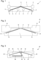
- THE figures 1 to 6 show different embodiments of a piezoelectric resonator, particularly used in a rotary motor.
- the motor can in particular be used in a timepiece to operate a display device comprising hands arranged on a dial.
- the piezoelectric resonator 1, 10, 20, 30, 40 preferably extends substantially in a plane.
- the first embodiment of piezoelectric resonator comprises a base 3, which here has a substantially triangular shape, preferably isosceles.
- the base 3 has two holes 11 to be able to assemble the base on a plate or on a bridge, in particular in a watch movement.
- the triangle has a main vertex and two opposite eccentric vertices.
- the triangle here has two equal sides and a base of length greater than the height, preferably at least twice as long, or even four or five times as long.
- the two opposite vertices each include a protrusion 5 extending towards the top of the triangle.
- the resonator 1 further comprises an oscillating mass 2.
- the oscillating mass 2 comprises a main arm at the ends of which two weights 4 are arranged.
- the arm comprises a stud 8 arranged in its middle and oriented towards the base 3.
- the arm is arranged tangentially to the main vertex of the triangle.
- the arm is substantially straight, except at the middle where it forms a triangular step to correspond to the main vertex of the triangle.
- the stud 8 is arranged inside the triangular recess.
- the oscillating mass 2 and the base 3 are preferably arranged in the same plane.
- the resonator comprises a guide with flexible blades connecting the oscillating mass 2 to the base 3, so as to be able to oscillate the oscillating mass 2 around a center of rotation in a pendulum movement.
- the center of rotation is arranged substantially in the middle of the oscillating mass 2, that is to say in the middle of the arm, preferably at the center of mass of the oscillating mass 2.
- the flexible guide includes two flexible blades.
- a first flexible blade 6 and a second flexible blade 7 are connected to the same central part of the oscillating mass 2, here the stud 8.
- the first flexible blade 6 and the second flexible blade 7 are also connected to two opposite eccentric parts of the base 3, here the two protrusions 5.
- each flexible blade 6, 7 connects a protrusion 5 of the base 3 to the stud 8 of the oscillating mass, along one of the equal sides of the isosceles triangle.
- the first 6 and the second flexible blade 7 form a non-zero angle between them, the angle being between 30° and 150°, preferably between 60° and 130°, or even between 90° and 120°.
- the flexible blades 6, 7 each comprise a piezoelectric material, which is operable to actuate the flexible blades and cause the oscillating mass to oscillate relative to the base.
- the material piezoelectric piezoelectric is arranged on each flexible blade 6, 7 in entirety.
- Flexible blades for example, have a layer of piezoelectric material sandwiched between two layers of electrodes.
- the protrusions 5 comprise several electrical contacts 9 connected to the electrode layers to receive an electrical voltage and actuate the piezoelectric layers of the flexible blades.
- the piezoelectric layers are preferably formed of a crystalline or polycrystalline material, for example ceramic of the KNN type (for sodium potassium niobate) or of the PZT type (for lead titano-zirconates), the flexible blades 6, 7 having a thickness allowing them to deform.
- a crystalline or polycrystalline material for example ceramic of the KNN type (for sodium potassium niobate) or of the PZT type (for lead titano-zirconates), the flexible blades 6, 7 having a thickness allowing them to deform.
- the flexible blades 6, 7 deform alternately laterally towards the center and the outside. Activation is produced with an alternating voltage.
- the oscillating mass makes small oscillations around the center of rotation corresponding to the crossing point of the two flexible blades , here at the level of pad 8.
- the oscillating mass 2 oscillates and the two weights 4 move laterally at a certain frequency, preferably at the resonance frequency.
- the base 13 and the protrusions 25 are substantially identical to the first embodiment.
- the third embodiment of a resonator 20 of figures 3 And 4 shows a resonator provided with a flexible guide with three flexible blades 26, 27, 28.
- the resonator is similar to the first two embodiments regarding the shape of the base 23 and the protrusions 25.
- the base 23 includes a channel 21 open from the main top to the inside of the base 23.
- the channel 21 forms an elbow in the base 23.
- a first flexible blade 26 connects the stud of the oscillating mass 22 to the base 23 between the second 27 and the third flexible blade 28.
- the second 27 and the third flexible blade 28 are arranged like the flexible blades of the first of the second embodiment. They form a non-zero angle between them, the angle being between 30° and 150°, preferably between 60° and 130°, or even between 90° and 120°, the first flexible blade. In this embodiment, these two flexible blades do not include piezoelectric material.
- the second 27 and the third flexible blade 28 are connected to the same central part of the oscillating mass 22 and to two opposite protrusions 25 eccentric from the base 23.
- the second 27 and the third blade 28 are uncrossed and move apart from the central part, here a stud of the oscillating mass 22 up to the eccentric parts of the base 23.
- the first flexible blade 26 is actuated using electrical contacts mounted on the base 23, not shown in the figures.
- the first flexible blade 26 extends in the bent channel 21 to a fixing point at the bottom of the channel 21.
- the first flexible blade 26 comprises a portion 29 provided with piezoelectric material at the bottom of channel 21 after the elbow, and a rigid portion 31 at the entrance to channel 21.
- the two portions 29, 31 are separated by a flexible neck arranged at the elbow.
- FIG. 4 is an enlargement of the Figure 3 , the central zone of the first flexible blade 26 being eccentric by a non-zero distance r relative to the crossing point of the second 27 and the third flexible blade 28, so that when the first flexible blade 26 is actuated, alternately , it pulls the oscillating mass 22 to one side, then releases it to make it oscillate around a center of rotation passing through the crossing point of the first two flexible blades 26, 27.
- the oscillating mass 32 comprises a main arm, a first flyweight 34 at a first end, and a second flyweight 35 at a second end, this second flyweight 35 forming a rigid elbow folded under the main arm.
- the resonator comprises a flexible guide provided with a first flexible blade 36 connecting the oscillating mass 32 to the base 33, from the end of the folded elbow, the first flexible blade 36 extending in the oblique channel 39 up to the second connection point at the bottom of the oblique channel 39.
- the flexible guide comprises a second flexible blade 37 extending parallel to the arm of the oscillating mass 32, from a first corner of the base 33 to an engagement point inside the folded elbow of the oscillating mass 32
- the second flexible blade 37 is arranged above the first flexible blade 36.
- the base 33 has a first point of engagement of the second flexible blade 37, at the level of the first flyweight 34, and a second point of engagement here arranged at 45° counterclockwise (non-limiting value), connected to the first flexible blade 36.
- the second point mounting is arranged in an oblique channel 38 open from a first corner of the base 33.
- the first flexible blade 36 and the second flexible blade 37 extend so as to form a non-zero angle between 10° and 80°, preferably between 30° and 60°, or even between 40° and 50°.
- the two flexible blades 36, 37 comprise a piezoelectric material, placed here entirely on the second flexible blade 37, and partly on the first flexible blade 36.
- the actuation of the flexible blades 36, 37 is identical to that of the embodiments previous, thanks to electrical contacts not shown in the figures.
- the configuration of this embodiment is different from the other embodiments, but the oscillating mass 32 oscillates in a similar manner, that is to say around an axis located at the intersection of the neutral fibers of the two flexible blades 36 , 37.
- the oscillating mass 42 comprising an arm connecting two weights 44, 45.
- the base 43 has a rectangular shape.
- the resonator 40 comprises a first flexible blade 46 in the shape of a U, connecting the oscillating mass 42 to the base 43.
- the U is arranged parallel to the arm and to the base 43.
- a first end 48 of the U is connected to the base 43, and a second end 49 of the U, extending further from the center than the first end 48, is connected to a flyweight 45 of the oscillating mass 42.
- the first flexible U-shaped blade 46 comprises a piezoelectric material, preferably over its entire length.
- the resonator also includes a second flexible blade 47 forming an active ratchet blade.
- the second flexible blade 47 is arranged on the other side of the arm relative to the first flexible blade 46. preferably, the second flexible blade 47 does not include piezoelectric material.
- the oscillating mass 42 and the weights 44, 45 oscillate around a center of rotation.
- the center of rotation is arranged on the center of gravity of the oscillating mass 42.
- the actuation of the first flexible blade 46 is carried out using electrical contacts mounted on the base 43, not shown in the figures.
- the resonators 1, 10, 20, 30 preferably comprise a monocrystalline or polycrystalline material, such as silicon, glass, ceramic, or a metal.
- the resonators 1, 10, 20, 30 are for example obtained by photo-lithographic micro-machining processes of the MEMS type (for micro-electro mechanical systems).
- the qualities of rigidity, elasticity and the machining precision of such materials confer a high quality of resonance to the resonators 1, 10, 20, 30.
- non-magnetism and low conductivity characteristics of some of these materials make it possible to obtain excellent resistance to high-value direct and alternating magnetic fields.
- the resonators 1, 10, 20, 30 are configured to oscillate the oscillating mass 2, 12, 22, 32, 42 at the natural frequency of the resonator 1, 10, 20, 30, 40.
- FIG. 7 shows an embodiment of a rotary piezoelectric motor 50, in particular for a display device for a timepiece.
- the motor can in particular be used in a timepiece to operate a display device, such as hands arranged on a dial.
- the piezoelectric motor 50 is configured to be able to rotate and operate a mechanical gear transmission of the display device.
- the piezoelectric motor 50 comprises a piezoelectric resonator according to the invention, here the piezoelectric resonator 30 of the fourth embodiment of the Figure 5 .
- the other embodiments of piezoelectric resonators can also be used without changing the operation of the piezoelectric motor 50.
- the piezoelectric resonator 30 is assembled to a plate by its base 33.
- the piezoelectric motor 50 further comprises a toothed movable wheel 51 and two pawls 52, 53 configured to rotate the movable wheel 51 in one direction.
- the movable wheel 51 preferably comprises peripheral teeth, preferably asymmetrical, and which defines the direction of rotation.
- the movable wheel 50 is connected to a cog equipped with needles of the display device.
- the first pawl 52 is active and has the function of rotating the movable wheel 51 in a counterclockwise direction, while the second pawl 53 is passive and retains the movable wheel 51, when the movable wheel 51 has rotated, while the first pawl 52 active resets on the next tooth of the rotor.
- Each pawl 52, 53 comprises a flexible blade 54 provided with a tooth 55, preferably asymmetrical, at its end.
- the rotation of the mobile wheel 51 is generated thanks to the movement of the first active pawl 52.
- the first pawl 52 is mounted on the oscillating mass 32 of the piezoelectric resonator 30.
- the first pawl 52 also oscillates, so that it pushes or pulls the mobile toothed wheel 51 in a first direction depending on the positioning of the piezoelectric resonator relative to the mobile wheel 51.
- the second pawl 53 is either assembled directly on the plate or on a plate bridge, or more advantageously integral with the base 30 to limit the positioning error due to the sequence of assembly tolerances. Its function is to prevent the gear wheel from rotating in the opposite direction to the first direction.
- the tooth 55 of the second pawl 53 is configured to cooperate with the asymmetrical teeth, so as to let the movable wheel 51 rotate in the first direction, and to block it in the opposite direction.
- the flexible arms 54 of the pawls 52, 53 are in the relaxed straight position, when the tooth 55 is inserted at the bottom of the teeth of the toothed wheel 51, while it is armed and curved, when it is pushed back outwards by the teeth, when the toothed wheel 51 turns in the first direction.
- the resonance frequency or natural frequency of the motor 50 is adapted to the frequency of the quartz, which is used to regulate the running of the movement.
- an excitation frequency corresponding to a submultiple of the quartz frequency which is generally 32764 Hz.
- a frequency of 128 Hz we choose a frequency of 128 Hz.
- the frequency of the motor 50 is preferably adjusted and tuned to the excitation frequency so that its oscillation amplitude does not fall below 90-95% of the maximum amplitude.
- the second pawl 53 can be configured to serve as a step sensor, in order to determine the distance or the speed of rotation of the movable wheel 51.
- the flexible arm 54 of the second pawl 53 is provided with a piezoelectric material connected to a counting unit.
- the counting unit records a rotation of the mobile wheel 51 of one tooth.
Landscapes
- Physics & Mathematics (AREA)
- General Physics & Mathematics (AREA)
- Engineering & Computer Science (AREA)
- General Engineering & Computer Science (AREA)
- Mechanical Engineering (AREA)
- Acoustics & Sound (AREA)
- General Electrical Machinery Utilizing Piezoelectricity, Electrostriction Or Magnetostriction (AREA)
Priority Applications (4)
| Application Number | Priority Date | Filing Date | Title |
|---|---|---|---|
| EP22216410.5A EP4391347A1 (de) | 2022-12-23 | 2022-12-23 | Piezoelektrischer resonator mit flexibler führung, insbesondere für rotationsmotoren von uhrwerken |
| US18/528,966 US20240210891A1 (en) | 2022-12-23 | 2023-12-05 | Piezoelectric resonator with flexible guide, especially for clock rotary motors |
| JP2023206690A JP7695988B2 (ja) | 2022-12-23 | 2023-12-07 | 特に計時器用回転モーターのための、フレキシブルガイドを備える圧電共振器 |
| CN202311728394.8A CN118249773A (zh) | 2022-12-23 | 2023-12-15 | 特别是用于钟表旋转电机的具有柔性导向件的压电谐振器 |
Applications Claiming Priority (1)
| Application Number | Priority Date | Filing Date | Title |
|---|---|---|---|
| EP22216410.5A EP4391347A1 (de) | 2022-12-23 | 2022-12-23 | Piezoelektrischer resonator mit flexibler führung, insbesondere für rotationsmotoren von uhrwerken |
Publications (1)
| Publication Number | Publication Date |
|---|---|
| EP4391347A1 true EP4391347A1 (de) | 2024-06-26 |
Family
ID=84602535
Family Applications (1)
| Application Number | Title | Priority Date | Filing Date |
|---|---|---|---|
| EP22216410.5A Pending EP4391347A1 (de) | 2022-12-23 | 2022-12-23 | Piezoelektrischer resonator mit flexibler führung, insbesondere für rotationsmotoren von uhrwerken |
Country Status (4)
| Country | Link |
|---|---|
| US (1) | US20240210891A1 (de) |
| EP (1) | EP4391347A1 (de) |
| JP (1) | JP7695988B2 (de) |
| CN (1) | CN118249773A (de) |
Citations (5)
| Publication number | Priority date | Publication date | Assignee | Title |
|---|---|---|---|---|
| FR1562662A (de) * | 1967-05-12 | 1969-04-04 | ||
| DE1945448A1 (de) * | 1969-09-08 | 1971-03-11 | Siemens Ag | Piezoelektrisch anzutreibender Biegekoerper,insbesondere fuer Uhren und Relais |
| EP0587031A1 (de) | 1992-09-09 | 1994-03-16 | Asulab S.A. | Uhr mit aus einem piezoelektrischen Motor bestehenden Antriebsmittel |
| CH709512B1 (fr) | 2013-01-07 | 2018-09-14 | Timex Group Usa Inc | Dispositif d'entraînement de mems bidirectionnel. |
| EP3451072A1 (de) * | 2017-08-29 | 2019-03-06 | The Swatch Group Research and Development Ltd | Isochrones drehgelenk für uhrresonator |
Family Cites Families (2)
| Publication number | Priority date | Publication date | Assignee | Title |
|---|---|---|---|---|
| JPS62272575A (ja) * | 1986-05-20 | 1987-11-26 | Matsushita Electric Works Ltd | 圧電アクチユエ−タ |
| EP3206089B1 (de) | 2016-02-10 | 2018-12-19 | The Swatch Group Research and Development Ltd. | Resonatormechanismus eines uhrwerks |
-
2022
- 2022-12-23 EP EP22216410.5A patent/EP4391347A1/de active Pending
-
2023
- 2023-12-05 US US18/528,966 patent/US20240210891A1/en active Pending
- 2023-12-07 JP JP2023206690A patent/JP7695988B2/ja active Active
- 2023-12-15 CN CN202311728394.8A patent/CN118249773A/zh active Pending
Patent Citations (5)
| Publication number | Priority date | Publication date | Assignee | Title |
|---|---|---|---|---|
| FR1562662A (de) * | 1967-05-12 | 1969-04-04 | ||
| DE1945448A1 (de) * | 1969-09-08 | 1971-03-11 | Siemens Ag | Piezoelektrisch anzutreibender Biegekoerper,insbesondere fuer Uhren und Relais |
| EP0587031A1 (de) | 1992-09-09 | 1994-03-16 | Asulab S.A. | Uhr mit aus einem piezoelektrischen Motor bestehenden Antriebsmittel |
| CH709512B1 (fr) | 2013-01-07 | 2018-09-14 | Timex Group Usa Inc | Dispositif d'entraînement de mems bidirectionnel. |
| EP3451072A1 (de) * | 2017-08-29 | 2019-03-06 | The Swatch Group Research and Development Ltd | Isochrones drehgelenk für uhrresonator |
Also Published As
| Publication number | Publication date |
|---|---|
| JP7695988B2 (ja) | 2025-06-19 |
| US20240210891A1 (en) | 2024-06-27 |
| JP2024091488A (ja) | 2024-07-04 |
| CN118249773A (zh) | 2024-06-25 |
Similar Documents
| Publication | Publication Date | Title |
|---|---|---|
| EP2105806B1 (de) | Hemmungsmechanismus | |
| EP2990885B1 (de) | Mechanisches Uhrwerk mit magnetischem Hemmungsmechanismus | |
| EP2405313B1 (de) | Spiralfeder mit unbeweglichem Massenzentrum | |
| EP3030938B1 (de) | Reglersystem für eine mechanische uhr | |
| EP2891930A2 (de) | Vorrichtung zur Regulierung der Winkelgeschwindigkeit einer Triebfeder in einem Uhrwerk, das einen magnetischen Hemmungsmechanismus umfasst | |
| EP0587031B1 (de) | Uhr mit aus einem piezoelektrischen Motor bestehenden Antriebsmittel | |
| WO2017068538A9 (fr) | Oscillateur pour un mouvement horloger mécanique | |
| CH715049A2 (fr) | Pièce d'horlogerie comprenant un tourbillon. | |
| EP3044637A1 (de) | Uhrwerkresonator und anordnung mit einem derartigen resonator und hemmwerk | |
| EP0580049A1 (de) | Piezo-elektrischer Motor | |
| EP4391347A1 (de) | Piezoelektrischer resonator mit flexibler führung, insbesondere für rotationsmotoren von uhrwerken | |
| EP4198648A1 (de) | Piezoelektrischer umlaufmotor, insbesondere für uhren | |
| EP4391348B1 (de) | Piezoelektrischer resonator mit doppeltem rcc-schwenkpunkt, insbesondere für rotationsmotoren von uhrwerken | |
| CH720388A2 (fr) | Résonateur piézoélectrique, moteur piézoélectrique et pièce d'horlogerie | |
| CH720391A2 (fr) | Résonateur piézoélectrique, moteur piézoélectrique et pièce d'horlogerie | |
| EP3451073B1 (de) | Uhrwerkoszillator mit flexiblen führungen mit grosser winkelförmiger laufbahn | |
| EP3944027A1 (de) | Tragbares gerät, insbesondere armbanduhr, das mit einer stromquellevorrichtung mit einem elektromechanischen wandler ausgestattet ist | |
| EP4390557A1 (de) | Piezoelektrischer resonator mit spiralfeder, insbesondere für einen rotierenden uhrwerk | |
| CH720393A2 (fr) | Résonateur piézoélectrique, moteur piézoélectrique et pièce d'horlogerie | |
| EP4432020A1 (de) | Uhrwerk | |
| EP4391349B1 (de) | Stossfester piezoelektrischer rotationsmotor, insbesondere für uhrwerke | |
| EP3140698B1 (de) | Stimmgabel mechanischen oszillator für uhrwerk | |
| CH720396A2 (fr) | Moteur rotatif piézoélectrique résistant aux chocs, notamment pour l'horlogerie | |
| WO2024141600A1 (fr) | Système réglant pour mouvement horloger | |
| EP4643187A1 (de) | Regulierungssystem für uhrwerk |
Legal Events
| Date | Code | Title | Description |
|---|---|---|---|
| PUAI | Public reference made under article 153(3) epc to a published international application that has entered the european phase |
Free format text: ORIGINAL CODE: 0009012 |
|
| STAA | Information on the status of an ep patent application or granted ep patent |
Free format text: STATUS: THE APPLICATION HAS BEEN PUBLISHED |
|
| AK | Designated contracting states |
Kind code of ref document: A1 Designated state(s): AL AT BE BG CH CY CZ DE DK EE ES FI FR GB GR HR HU IE IS IT LI LT LU LV MC ME MK MT NL NO PL PT RO RS SE SI SK SM TR |
|
| P01 | Opt-out of the competence of the unified patent court (upc) registered |
Free format text: CASE NUMBER: APP_50401/2024 Effective date: 20240905 |
|
| STAA | Information on the status of an ep patent application or granted ep patent |
Free format text: STATUS: REQUEST FOR EXAMINATION WAS MADE |
|
| 17P | Request for examination filed |
Effective date: 20241218 |
|
| GRAP | Despatch of communication of intention to grant a patent |
Free format text: ORIGINAL CODE: EPIDOSNIGR1 |
|
| STAA | Information on the status of an ep patent application or granted ep patent |
Free format text: STATUS: GRANT OF PATENT IS INTENDED |
|
| INTG | Intention to grant announced |
Effective date: 20260210 |