EP2960741B1 - Robot de service - Google Patents
Robot de service Download PDFInfo
- Publication number
- EP2960741B1 EP2960741B1 EP15170499.6A EP15170499A EP2960741B1 EP 2960741 B1 EP2960741 B1 EP 2960741B1 EP 15170499 A EP15170499 A EP 15170499A EP 2960741 B1 EP2960741 B1 EP 2960741B1
- Authority
- EP
- European Patent Office
- Prior art keywords
- detection device
- service robot
- optical detection
- autonomous service
- autonomous
- Prior art date
- Legal status (The legal status is an assumption and is not a legal conclusion. Google has not performed a legal analysis and makes no representation as to the accuracy of the status listed.)
- Active
Links
Images

Classifications
-
- G—PHYSICS
- G05—CONTROLLING; REGULATING
- G05D—SYSTEMS FOR CONTROLLING OR REGULATING NON-ELECTRIC VARIABLES
- G05D1/00—Control of position, course, altitude or attitude of land, water, air or space vehicles, e.g. using automatic pilots
- G05D1/02—Control of position or course in two dimensions
- G05D1/021—Control of position or course in two dimensions specially adapted to land vehicles
- G05D1/0231—Control of position or course in two dimensions specially adapted to land vehicles using optical position detecting means
- G05D1/0234—Control of position or course in two dimensions specially adapted to land vehicles using optical position detecting means using optical markers or beacons
- G05D1/0236—Control of position or course in two dimensions specially adapted to land vehicles using optical position detecting means using optical markers or beacons in combination with a laser
-
- E—FIXED CONSTRUCTIONS
- E04—BUILDING
- E04H—BUILDINGS OR LIKE STRUCTURES FOR PARTICULAR PURPOSES; SWIMMING OR SPLASH BATHS OR POOLS; MASTS; FENCING; TENTS OR CANOPIES, IN GENERAL
- E04H4/00—Swimming or splash baths or pools
- E04H4/14—Parts, details or accessories not otherwise provided for
- E04H4/16—Parts, details or accessories not otherwise provided for specially adapted for cleaning
- E04H4/1654—Self-propelled cleaners
-
- G—PHYSICS
- G01—MEASURING; TESTING
- G01S—RADIO DIRECTION-FINDING; RADIO NAVIGATION; DETERMINING DISTANCE OR VELOCITY BY USE OF RADIO WAVES; LOCATING OR PRESENCE-DETECTING BY USE OF THE REFLECTION OR RERADIATION OF RADIO WAVES; ANALOGOUS ARRANGEMENTS USING OTHER WAVES
- G01S17/00—Systems using the reflection or reradiation of electromagnetic waves other than radio waves, e.g. lidar systems
- G01S17/88—Lidar systems specially adapted for specific applications
- G01S17/93—Lidar systems specially adapted for specific applications for anti-collision purposes
- G01S17/931—Lidar systems specially adapted for specific applications for anti-collision purposes of land vehicles
-
- G—PHYSICS
- G05—CONTROLLING; REGULATING
- G05D—SYSTEMS FOR CONTROLLING OR REGULATING NON-ELECTRIC VARIABLES
- G05D1/00—Control of position, course, altitude or attitude of land, water, air or space vehicles, e.g. using automatic pilots
- G05D1/02—Control of position or course in two dimensions
- G05D1/021—Control of position or course in two dimensions specially adapted to land vehicles
- G05D1/0231—Control of position or course in two dimensions specially adapted to land vehicles using optical position detecting means
- G05D1/0246—Control of position or course in two dimensions specially adapted to land vehicles using optical position detecting means using a video camera in combination with image processing means
- G05D1/0248—Control of position or course in two dimensions specially adapted to land vehicles using optical position detecting means using a video camera in combination with image processing means in combination with a laser
-
- G—PHYSICS
- G01—MEASURING; TESTING
- G01S—RADIO DIRECTION-FINDING; RADIO NAVIGATION; DETERMINING DISTANCE OR VELOCITY BY USE OF RADIO WAVES; LOCATING OR PRESENCE-DETECTING BY USE OF THE REFLECTION OR RERADIATION OF RADIO WAVES; ANALOGOUS ARRANGEMENTS USING OTHER WAVES
- G01S17/00—Systems using the reflection or reradiation of electromagnetic waves other than radio waves, e.g. lidar systems
- G01S17/88—Lidar systems specially adapted for specific applications
- G01S17/89—Lidar systems specially adapted for specific applications for mapping or imaging
- G01S17/894—Three-dimensional [3D] imaging with simultaneous measurement of time-of-flight at a two-dimensional [2D] array of receiver pixels, e.g. time-of-flight cameras or flash lidar
-
- G—PHYSICS
- G05—CONTROLLING; REGULATING
- G05D—SYSTEMS FOR CONTROLLING OR REGULATING NON-ELECTRIC VARIABLES
- G05D1/00—Control of position, course, altitude or attitude of land, water, air or space vehicles, e.g. using automatic pilots
- G05D1/02—Control of position or course in two dimensions
- G05D1/021—Control of position or course in two dimensions specially adapted to land vehicles
- G05D1/0212—Control of position or course in two dimensions specially adapted to land vehicles with means for defining a desired trajectory
- G05D1/0225—Control of position or course in two dimensions specially adapted to land vehicles with means for defining a desired trajectory involving docking at a fixed facility, e.g. base station or loading bay
-
- G—PHYSICS
- G05—CONTROLLING; REGULATING
- G05D—SYSTEMS FOR CONTROLLING OR REGULATING NON-ELECTRIC VARIABLES
- G05D1/00—Control of position, course, altitude or attitude of land, water, air or space vehicles, e.g. using automatic pilots
- G05D1/02—Control of position or course in two dimensions
- G05D1/021—Control of position or course in two dimensions specially adapted to land vehicles
- G05D1/0268—Control of position or course in two dimensions specially adapted to land vehicles using internal positioning means
- G05D1/0272—Control of position or course in two dimensions specially adapted to land vehicles using internal positioning means comprising means for registering the travel distance, e.g. revolutions of wheels
Definitions
- the invention relates to an autonomous service robot having the features of claim 1.
- the optical detection device is preferably provided at least partially for detecting a spatial environment.
- “autonomously” is to be understood in particular as “working independently”.
- the autonomous service robot preferably carries out work, at least to a large extent, independently of intervention by an operator.
- the autonomous service robot is provided to start or end the work at least partially automatically and/or to select at least one parameter, such as a route parameter in particular, and/or a reversal point, etc., at least partially automatically.
- the autonomous service robot is particularly preferably provided at least in part to provide at least one service for an operator and/or people in general.
- the autonomous service robot can preferably be designed in various ways that appear sensible to the person skilled in the art, such as in particular as an autonomous sweeper, an autonomous vacuum cleaner, an autonomous swimming pool cleaning machine, an autonomous floor cleaning robot and/or more preferably an autonomous lawnmower. In principle, however, other autonomous service robots that appear sensible to a person skilled in the art are also conceivable.
- environment detection is to be understood in particular as a, in particular virtual, detection of at least one parameter that characterizes an environment, in particular for a work area, of the autonomous service robot.
- the environment detection includes at least a level or step detection (Cliff Detection), an obstacle detection and / or another function that appears useful to a person skilled in the art.
- the optical detection device is provided for creating a topographical map that includes information on heights and/or scale and/or subsoil conditions and possible obstacles from the working area and/or working area boundaries, in particular natural working area boundaries.
- a “transit time measurement” is to be understood in particular as a method for, in particular indirectly, determining a distance at least partially by measuring the time required for a signal to run through the measurement section.
- the time is preferably measured which the signal requires from being emitted until it is returned by a reflection.
- the signal preferably has at least an almost continuous modulation, via the evaluation of which the transit time can advantageously be determined.
- other configurations of the signal that appear sensible to a person skilled in the art, such as sound, for example, are also conceivable.
- Provided is to be understood in particular as being specially configured, designed and/or equipped.
- the fact that an object is provided for a specific function is to be understood in particular to mean that the object fulfills and/or executes this specific function in at least one application and/or operating state.
- the design of the autonomous service robot according to the invention makes it possible to easily and advantageously detect the working area and achieve a preferably precise and advantageously reliable guidance of the autonomous service robot, in particular within a working area of the autonomous service robot. preferably in particular, moving or setting up a physical boundary can be avoided, which in turn means that the amount of work can be kept low.
- the optical detection device of the autonomous service robot can preferably include a control and/or regulation unit that is provided for evaluating at least one piece of detected information.
- a "control and/or regulation unit” is to be understood in particular as a unit that is used at least in part to actively influence and/or actively adapt and/or, in particular dynamically, change the operation of the autonomous service robot is preferably provided according to an algorithm.
- the control and/or regulation unit preferably comprises a processor unit and a memory unit as well as at least one operating program stored in the memory unit.
- a “memory unit” is to be understood in particular as a unit which is intended to store at least one piece of information, advantageously independently of a power supply. As a result, the at least one piece of recorded information can advantageously be processed directly on the autonomous service robot.
- the optical detection device is provided at least partially for level and/or obstacle detection.
- level and/or obstacle detection means in particular a detection of a two-dimensional extension of the processing area of the autonomous service robot, in particular a detection of a deviation from a level configuration of the processing area of the autonomous service robot, such as a step or another, a Specialist as a reasonable appearing obstacle to be understood.
- the optical detection device comprises at least one wide-angle optical element and/or a zoom element.
- a "wide-angle optical element” is to be understood in particular as an element that is intended to capture an image area within an angle that is greater than the natural impression of the human eye.
- the at least one wide-angle optical element of the optical detection device is preferably provided to detect a diagonal image angle that is in particular at least 60°, preferably at least 70°, preferably at least 80° and particularly preferably at least 90°.
- values of the diagonal image angle of the at least one wide-angle optical element that appear sensible to a person skilled in the art are also conceivable.
- a “zoom element” is to be understood in particular as an element that has a variable focal length and that is provided for enlarging and/or reducing at least a part of an image section recorded by the optical recording device.
- the zoom element can be optical or digital.
- other configurations of the zoom element which appear sensible to a person skilled in the art are also conceivable.
- an advantageously large field of view of the detection area can be covered in an operating state of the autonomous service robot in a structurally simple and preferably cost-effective manner.
- the optical detection device includes at least one time-of-flight camera.
- a "time-of-flight camera” is to be understood in particular as a 3D camera system for executing a runtime measurement method, which in particular has a lighting unit for emitting light, at least one optic for collecting the reflected light of the lighting unit and comprises at least one sensor element for detecting a phase shift of the reflected light of the lighting unit.
- the time-of-flight camera is preferably provided to emit a light pulse in a number of directions simultaneously and to measure a propagation time of a reflecting component of a modulated light signal from the different directions.
- the time-of-flight camera is provided for a particular three-dimensional detection of a distance to at least two points at least partially by means of a light pulse, with an interference of the emitted light pulse and the reflected light pulse being detected and from this the distance to the at least two points is determined.
- the time-of-flight camera has a maximum extent of, in particular, a maximum of 50 mm, preferably a maximum of 40 mm and particularly preferably a maximum of 35 mm.
- the optical detection device comprises at least one laser scanner.
- a "laser scanner” is to be understood in particular as an element or a subassembly that is intended for a line and/or grid-like scanning of surfaces or bodies, in particular the area surrounding the autonomous service robot, with at least one laser beam in order to to measure the surroundings of the autonomous service robot and/or to at least partially generate an image of the surroundings of the autonomous service robot.
- the laser scanner preferably includes at least one sensor which is provided for deflecting and/or deflecting the at least one emitted laser beam.
- the laser scanner is in the form of an imaging laser scanner which is intended to record the intensity of the reflected signal in addition to the object geometry.
- the optical detection device advantageously comprises at least one lighting element which is provided at least partially for illuminating a detection region of the optical detection device.
- a contrast can thus advantageously be used to detect unevenness.
- the optical detection device comprises at least one lighting element which is at least partially provided for illuminating a detection region of the optical detection device at least partially by means of a pulsed light.
- illumination is to be understood in particular as an emission of light at least into the detection area of the optical detection device.
- pulsesed is to be understood in particular as meaning that the light is emitted in individual pulses, which have a pulse duration of at least almost 50 ns and/or a frequency of at least 100 Hz, preferably at least 130 Hz and particularly preferably of have at least nearly 160 Hz.
- other values for the pulse duration and/or for the frequency of the pulsed light that appear sensible to a person skilled in the art are also conceivable.
- the at least one lighting element of the optical detection device is provided at least partially for illuminating a detection area at least partially by means of infrared light.
- infrared light should be understood to mean electromagnetic waves, in particular light, in the spectral range, in particular between 1 mm and 780 nm.
- the optical detection device comprises a gesture control unit, which is provided for control based on at least one gesture of an operator detected by means of the optical detection device.
- the operator's gesture is formed at least in part by a hand signal.
- the base station has at least one reflective area, in particular that it is at least partially coated with a reflective lacquer.
- the reflection area can be designed as a mirror system, as an optical pattern, such as a cat's eye pattern or the like.
- a "reflective lacquer" is to be understood in particular as a material which, in a coated state of the base station, is intended to at least partially form a surface that is intended for this purpose, in particular at least 30%, preferably at least 50% and particularly preferably reflect back at least 70% of the incident light at a reflection angle that at least substantially corresponds to an angle of incidence. This allows an advantageously simple orientation of the autonomous service robot, especially in a Driving back the autonomous service robot to the base station and/or when docking can be achieved.
- the system has at least one reflection element, which comprises at least one reflection area, in particular at least partially a coating of reflective paint, and which is provided at least partially for orienting the at least one autonomous service robot.
- a "reflection element” is to be understood in particular as an element which at least partially has a surface which is intended for, in particular at least 30%, preferably at least 50% and particularly preferably at least 70% of the incident light at a reflection angle of corresponds at least essentially to an angle of incidence.
- the at least one reflection element is designed as a beacon.
- the at least one reflection element is preferably used as a landmark.
- the autonomous service robot according to the invention should not be limited to the application and embodiment described above.
- the autonomous service robot according to the invention can have a number of individual elements, components and units that differs from a number specified here in order to fulfill a function described herein.
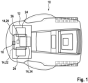
- an autonomous service robot 10 is shown.
- the autonomous service robot 10 is designed as an autonomous lawnmower.
- the autonomous service robot 10 is intended to mow a work area 32 .
- the working area 32 is formed by a meadow or a lawn of a garden.
- the autonomous service robot 10 it would also be conceivable for the autonomous service robot 10 to be formed by a vacuum cleaner robot or another service robot considered appropriate by a person skilled in the art and for the work area 32 to be formed accordingly by a room, for example.
- the autonomous service robot 10 can also be programmed for several work areas 32 .
- the different work areas 32 can be stored separately and selected separately depending on the current location of the autonomous service robot 10 .
- the autonomous service robot 10 has an optical detection device 12 which is provided for detecting the surroundings when the autonomous service robot 10 is in an operating state.
- the optical detection device 12 includes a transit time measuring unit 14 which is provided at least partially for detecting the surroundings of the autonomous service robot 10 by means of a transit time measurement.
- the optical detection device 12 is provided at least partially for level and/or obstacle detection.
- the optical detection device 12 is provided for detecting a level and for detecting an obstacle in an operating state of the autonomous service robot 10 by acquiring depth data.
- the optical detection device 12 is provided for detecting high-resolution depth data from an area surrounding the autonomous service robot 10 .
- the optical detection device 12 can be used to detect and estimate a free space in front of the autonomous service robot 10 and the working area 32 of the autonomous service robot 10 that is to be traveled through or processed. In addition, deviations from a plane, such as a step and/or a ditch, can be detected. Static and/or dynamic obstacles can be detected in the obstacle detection by the optical detection device 12 . When the obstacle is detected by the optical detection device 12, both static and dynamic obstacles can be detected and thus avoided. Advantageous navigation strategies can be achieved and the detected dynamic obstacles can be circumvented by specially adapted turning maneuvers, in particular due to the multitude of data recorded by the optical detection device 12 .
- the optical detection device 12 has a control and/or regulation unit 16 which is provided for evaluating at least one piece of detected information.
- the control and/or regulation unit 16 of the optical detection device 12 is designed as a control unit 34 which is provided for evaluating the information detected by the optical detection device 12 .
- the control unit 34 includes a ⁇ -controller, not shown.
- the control unit 34 is provided to calculate and create a processing sequence, according to which the autonomous service robot 10 is to process the work area 32, from the recorded information according to a stored control algorithm. Obstacles and steps should be recognized and avoided.
- the optical detection device 12 comprises a wide-angle optical element 18 and a zoom element 42.
- the wide-angle optical element 18 and the zoom element 42 of the optical detection device 12 are designed in one piece.
- the wide-angle optical element 18 of the optical detection device 12 comprises an optical lens.
- the wide-angle optical element 18 and the zoom element 42 of the optical detection device 12 are intended to capture an image area from within an angle larger than the natural perception of the human eye.
- the wide-angle optical element 18 of the optical detection device 12 detects a diagonal angle of view that is more than 60°.
- the diagonal angle of view of the wide-angle optical element 18 of the optical detection device 12 is 90°. It however, other configurations of the wide-angle optical element 18 that appear sensible to a person skilled in the art are also conceivable.
- an advantageously large field of view and a preferably large detection range 26 can be covered in an operating state of the autonomous service robot 10.
- the optical detection device 12 comprises a time-of-flight camera 20.
- the optical detection device 12 is at least partially formed by the time-of-flight camera 20.
- the time-of-flight camera 20 is provided for a three-dimensional acquisition of the surroundings of the autonomous service robot 10 by means of the transit time measurement.
- the optical detection device 12 also includes at least one lighting element 24, which is at least partially provided for illuminating the detection region 26 of the optical detection device 12 at least partially by means of a pulsed light.
- the lighting element 24 of the optical detection device 12 is also provided for illuminating a detection area 26 at least partially by means of infrared light.
- the optical detection device 12 has two lighting elements 24 which are provided for illuminating the detection area 26 of the optical detection device 12 by means of a pulsed light.
- the lighting elements 24 are each formed by an LED.
- the lighting elements 24 are each formed by an infrared LED. In an operating state, the lighting elements 24 emit light in a non-visible infrared range.
- the optical detection device 12 is also suitable at night for detecting the surroundings and for monitoring or identifying people.
- the light emitted by the lighting elements 24 is pulsed and emitted at a frequency of approximately 160 Hz.
- the time-of-flight camera 20 has a sensor unit 36 which is provided for detecting the light pulses reflected from the surroundings of the autonomous service robot 10 .
- the sensor unit 36 of the time-of-flight camera 20 has a plurality of photosensitive elements, not shown, which are provided for the detection of a picture element or pixel.
- the photosensitive elements are each formed by a photodiode.
- the time-of-flight camera 20 includes a filter element, not shown, which is provided for filtering specific wavelengths of incident light.
- the time-of-flight camera 20 of the optical detection device 12 is known as "PMD Cam-Board nano"camera.
- PMD Cam-Board nano is known as "PMD Cam-Board nano”camera.
- other configurations of the time-of-flight camera 20 that appear sensible to a person skilled in the art are also conceivable.
- the lighting elements 24 When the autonomous service robot 10 is in an operating state, the lighting elements 24 emit light pulses which are reflected by the surroundings of the autonomous service robot 10 . These reflected light pulses are bundled by the wide-angle optical element 18 and conducted to the sensor unit 36 via the filter element of the time-of-flight camera 20 .
- the sensor unit 36 of the time-of-flight camera 20 and the lighting elements 24 are each connected to the control unit 34 of the optical detection device 12 .
- a distance from the optical detection device 12 to a respective pixel in the vicinity of the autonomous service robot 10 can be calculated based on a measurement of the transit time that elapses between the light pulses being emitted by the lighting elements 24 and until they strike the photosensitive elements.
- the distance to a pixel can be determined with each of the photosensitive elements of the sensor unit 36 of the time-of-flight camera 20, so that a complete scene of the environment can be recorded from several pixels at the same time.
- the distance of the pixel is proportional to the propagation time of the light pulse.
- the optical detection device 12 can also be provided for gesture control of the autonomous service robot 10 by an operator.
- the optical detection device 12 includes a gesture control unit 44 which is provided for control based on at least one gesture of an operator detected by means of the optical detection device 12 .
- the time-of-flight camera 20 of the optical detection device 12 can detect the dynamic movements of the operator's extremities in the detection area 26 of the optical detection device 12 and compare them with predefined and stored movement patterns. As soon as a predefined movement pattern has been recognized, a command stored for this purpose can be executed by the autonomous service robot 10 .
- an advantageously user-friendly and simple control of the autonomous service robot 10 such as actively sending the autonomous service robot 10 back to a base station 28 or starting a recording of a work area 32 of the autonomous service robot 10, can be achieved.
- the optical detection device 12 includes a laser scanner 22 that replaces the time-of-flight camera 20 already described.
- the optical detection device 12 includes both at least one laser scanner 22 and at least one time-of-flight camera 20 and/or includes another camera system, in particular a three-dimensional one, that appears useful to a person skilled in the art.
- a function of the laser scanner 22 of the optical detection device 12 largely corresponds to the function of the time-of-flight camera 20 already described.
- the function of the laser scanner 22 differs from the function of the time-of-flight camera 20 already described only in this respect that the laser scanner 22 scans the detection area 26 of the surroundings of the autonomous service robot 10 and puts together an overall image of the surroundings of the autonomous service robot 10 from the individual pixels or image lines scanned one after the other.
- a system that includes the autonomous service robot 10 and the base station 28, with which the autonomous service robot 10 can be coupled and by means of which a battery of the autonomous service robot 10 can be charged with electrical energy.
- the system is in figure 2 shown schematically.
- the base station 28 has a reflective area, in particular a coating 38 with a reflective lacquer.
- the reflective lacquer is provided to advantageously strongly reflect the light pulses emitted by the lighting element 24 of the autonomous service robot 10, so that the time-of-flight camera 20 can preferably find the base station 28 quickly and advantageously reliably.
- the system also includes at least one reflection element 30 which has at least one reflection area, in particular at least partially includes a coating 40 made of a reflective paint and which is provided at least partially for orienting the autonomous service robot 10 .
- the system includes a number of reflection elements 30 which are provided for orienting the autonomous service robot 10 within the work area 32 .
- the reflection elements 30 are each formed by a beacon. However, other configurations of the reflection elements 30 that appear sensible to a person skilled in the art are also conceivable.
- the reflection elements 30 designed as beacons have at least partially a highly reflective surface. Advantageously good localization and orientation of the autonomous service robot 10 within the work area 32 in an operating state can be achieved by the reflection elements 30 . As a result, a boundary wire for delimiting the working area 32 of the autonomous service robot 10 can preferably be dispensed with.
Landscapes
- Engineering & Computer Science (AREA)
- Physics & Mathematics (AREA)
- Remote Sensing (AREA)
- Electromagnetism (AREA)
- General Physics & Mathematics (AREA)
- Radar, Positioning & Navigation (AREA)
- Automation & Control Theory (AREA)
- Architecture (AREA)
- Optics & Photonics (AREA)
- Aviation & Aerospace Engineering (AREA)
- Civil Engineering (AREA)
- Structural Engineering (AREA)
- Computer Networks & Wireless Communication (AREA)
- Computer Vision & Pattern Recognition (AREA)
- Multimedia (AREA)
- Control Of Position, Course, Altitude, Or Attitude Of Moving Bodies (AREA)
- Manipulator (AREA)
- Guiding Agricultural Machines (AREA)
Claims (13)
- Robot de service autonome, notamment tondeuse à gazon autonome ou aspirateur autonome, comprenant un dispositif de détection optique (12) destiné à détecter l'environnement, le dispositif de détection optique (12) comportant une unité de mesure du temps de propagation (14) qui est prévue au moins en partie pour détecter l'environnement au moyen d'une mesure du temps de propagation, le dispositif de détection optique (12) détectant puis cartographiant un environnement du robot de service autonome de sorte que le robot de service autonome puisse être guidé dans un état de fonctionnement à l'intérieur d'une zone de travail (32), le dispositif de détection optique (12) comportant une unité de commande et/ou de régulation (16) qui est prévue pour évaluer au moins une information détectée, caractérisé en ce que le dispositif de détection optique (12) est prévu pour créer une carte topographique qui comprend des informations sur les hauteurs et/ou l'échelle et/ou les conditions du sol et d'éventuels obstacles de la zone de travail (32) et/ou des limites de la zone de travail.
- Robot de service autonome selon la revendication 1, caractérisé en ce que le dispositif de détection optique (12) est prévu au moins en partie pour détecter un niveau et/ou un obstacle.
- Robot de service autonome selon l'une des revendications précédentes, caractérisé en ce que le dispositif de détection optique (12) comprend au moins un élément optique grand angle (18) et/ou un élément zoom (42).
- Robot de service autonome selon l'une des revendications précédentes, caractérisé en ce que le dispositif de détection optique (12) comprend au moins une caméra à temps de vol (20).
- Robot de service autonome selon l'une des revendications précédentes, caractérisé en ce que le dispositif de détection optique (12) comprend au moins un scanner laser (22).
- Robot de service autonome selon l'une des revendications précédentes, caractérisé en ce que le dispositif de détection optique (12) comprend au moins un élément d'éclairage (24) qui est prévu au moins en partie pour éclairer une zone de détection (26) du dispositif de détection optique (12).
- Robot de service autonome selon l'une des revendications précédentes, caractérisé en ce que le dispositif de détection optique (12) comprend au moins un élément d'éclairage (24) qui est prévu au moins en partie pour éclairer une zone de détection (26) du dispositif de détection optique (12) au moins en partie au moyen d'une lumière pulsée.
- Robot de service autonome selon la revendication 7, caractérisé en ce que l'au moins un élément d'éclairage (24) du dispositif de détection optique (12) est prévu au moins en partie pour éclairer une zone de détection (26) au moins en partie au moyen d'une lumière infrarouge.
- Robot de service autonome selon l'une des revendications précédentes, caractérisé en ce que le dispositif de détection optique (12) comprend une unité de commande gestuelle (44) qui est prévue pour effectuer une commande sur la base d'au moins un geste d'un opérateur détecté au moyen du dispositif de détection optique (12).
- Système comprenant au moins une station de base (28) et au moins un robot de service autonome selon l'une des revendications précédentes.
- Système selon la revendication 10, caractérisé en ce que la station de base (28) comporte au moins une zone réfléchissante, notamment partiellement revêtue d'une peinture réfléchissante.
- Système selon la revendication 10 ou 11, caractérisé par au moins un élément de réflexion (30) qui comprend au moins une zone de réflexion, notamment partiellement un revêtement (40) obtenu à partir d'une peinture réfléchissante, et qui est prévu au moins en partie pour orienter ledit au moins un robot de service autonome.
- Système au moins selon la revendication 12, caractérisé en ce que l'au moins un élément réfléchissant (30) est conçu comme une balise.
Applications Claiming Priority (1)
| Application Number | Priority Date | Filing Date | Title |
|---|---|---|---|
| DE102014212418.2A DE102014212418A1 (de) | 2014-06-27 | 2014-06-27 | Autonomer Serviceroboter |
Publications (3)
| Publication Number | Publication Date |
|---|---|
| EP2960741A2 EP2960741A2 (fr) | 2015-12-30 |
| EP2960741A3 EP2960741A3 (fr) | 2016-06-22 |
| EP2960741B1 true EP2960741B1 (fr) | 2023-04-19 |
Family
ID=53397813
Family Applications (1)
| Application Number | Title | Priority Date | Filing Date |
|---|---|---|---|
| EP15170499.6A Active EP2960741B1 (fr) | 2014-06-27 | 2015-06-03 | Robot de service |
Country Status (2)
| Country | Link |
|---|---|
| EP (1) | EP2960741B1 (fr) |
| DE (1) | DE102014212418A1 (fr) |
Families Citing this family (22)
| Publication number | Priority date | Publication date | Assignee | Title |
|---|---|---|---|---|
| US10167650B2 (en) | 2016-08-10 | 2019-01-01 | Aquatron Robotic Technology Ltd. | Concurrent operation of multiple robotic pool cleaners |
| DE102016226285A1 (de) * | 2016-12-29 | 2018-07-05 | Robert Bosch Gmbh | Haltesystem, insbesondere für Agraranwendungen |
| SE540794C2 (en) * | 2017-02-06 | 2018-11-13 | Acconeer Ab | An autonomous mobile robot with radar sensors |
| DE102017203055A1 (de) * | 2017-02-24 | 2018-08-30 | Robert Bosch Gmbh | Verfahren zu einer Erfassung zumindest eines Arbeitsbereichs eines autonomen Arbeitsgeräts |
| DE102017217412A1 (de) | 2017-09-29 | 2019-04-04 | Robert Bosch Gmbh | Verfahren, Vorrichtung und Computerprogramm zum Betreiben eines Robotersteuerungssystems |
| DE102018200726A1 (de) * | 2018-01-17 | 2019-07-18 | BSH Hausgeräte GmbH | Reinigungsroboter und Verfahren zur Steuerung eines Reinigungsroboters |
| EP3521532B1 (fr) * | 2018-02-04 | 2021-01-06 | Maytronics Ltd. | Robot de nettoyage de piscine et procédé d'imagerie d'une piscine |
| ES3021228T3 (en) | 2018-08-20 | 2025-05-26 | Zodiac Pool Systems Llc | Cleaning system involving mapping and tracking methods |
| US20220010573A1 (en) * | 2018-11-27 | 2022-01-13 | Aquatron Robotic Technology Ltd. | Concurrent operation of multiple robotic pool cleaners |
| US12296694B2 (en) | 2021-03-10 | 2025-05-13 | Techtronic Cordless Gp | Lawnmowers |
| DE102021203583B4 (de) | 2021-04-12 | 2024-09-12 | BSH Hausgeräte GmbH | Mobiles, selbstfahrendes Gerät |
| US20220333395A1 (en) * | 2021-04-15 | 2022-10-20 | Zodiac Pool Care Europe | Underwater time-of-flight sensing systems principally for use in connection with swimming pools or spas |
| DE102021206142A1 (de) | 2021-06-16 | 2022-12-22 | BSH Hausgeräte GmbH | Mobiles, selbstfahrendes Gerät |
| US12443180B2 (en) | 2021-11-10 | 2025-10-14 | Techtronic Cordless Gp | Robotic lawn mowers |
| AU2023200381A1 (en) | 2022-01-31 | 2023-08-17 | Techtronic Cordless Gp | Robotic garden tool |
| AU2023247283A1 (en) * | 2022-03-29 | 2024-08-29 | Zodiac Pool Care Europe | Automatic swimming pool cleaner systems with improved visual communication |
| EP4270138A1 (fr) | 2022-04-28 | 2023-11-01 | Techtronic Cordless GP | Création d'une limite virtuelle pour un outil de jardin robotisé |
| US12472611B2 (en) | 2022-05-31 | 2025-11-18 | Techtronic Cordless Gp | Peg driver |
| EP4310621B1 (fr) | 2022-07-19 | 2025-02-12 | Techtronic Cordless GP | Dispositif d'affichage pour commander un outil robotique |
| AU2023206123A1 (en) | 2022-07-29 | 2024-02-15 | Techtronic Cordless Gp | Generation of a cryptography key for a robotic garden tool |
| US20240254796A1 (en) * | 2023-01-27 | 2024-08-01 | Zodiac Pool Systems Llc | Automatic swimming pool cleaners especially adept at climbing and cleaning pool stairs |
| CN119641145B (zh) * | 2025-02-17 | 2025-05-16 | 深圳市元鼎智能创新有限公司 | 水池自动清洁设备及其控制方法 |
Citations (4)
| Publication number | Priority date | Publication date | Assignee | Title |
|---|---|---|---|---|
| US20060076039A1 (en) * | 2004-10-12 | 2006-04-13 | Samsung Gwangju Electronics Co., Ltd | Robot cleaner coordinates compensation method and a robot cleaner system using the same |
| US20100063648A1 (en) * | 2008-09-11 | 2010-03-11 | Noel Wayne Anderson | Distributed knowledge base program for vehicular localization and work-site management |
| US20130261871A1 (en) * | 2012-04-02 | 2013-10-03 | Google Inc. | Gesture-Based Automotive Controls |
| EP2680097A1 (fr) * | 2012-06-27 | 2014-01-01 | Miele & Cie. KG | Robot de nettoyage et procédé de commande associé |
Family Cites Families (6)
| Publication number | Priority date | Publication date | Assignee | Title |
|---|---|---|---|---|
| US5995884A (en) * | 1997-03-07 | 1999-11-30 | Allen; Timothy P. | Computer peripheral floor cleaning system and navigation method |
| CA2578525A1 (fr) * | 2004-08-27 | 2006-03-09 | Sharper Image Corporation | Robot nettoyeur comprenant une unite a depression amelioree |
| DE102007053310A1 (de) * | 2007-11-08 | 2009-06-10 | Robert Bosch Gmbh | Roboterfahrzeug sowie Ansteuerverfahren für ein Roboterfahrzeug |
| US8918209B2 (en) * | 2010-05-20 | 2014-12-23 | Irobot Corporation | Mobile human interface robot |
| DE102012002922A1 (de) * | 2012-02-14 | 2013-08-14 | Audi Ag | Time-Of-Flight-Kamera für ein Kraftfahrzeug, Kraftfahrzeug und Verfahren zum Betrieb einer Time-Of-Flight-Kamera |
| US8972061B2 (en) * | 2012-11-02 | 2015-03-03 | Irobot Corporation | Autonomous coverage robot |
-
2014
- 2014-06-27 DE DE102014212418.2A patent/DE102014212418A1/de not_active Withdrawn
-
2015
- 2015-06-03 EP EP15170499.6A patent/EP2960741B1/fr active Active
Patent Citations (4)
| Publication number | Priority date | Publication date | Assignee | Title |
|---|---|---|---|---|
| US20060076039A1 (en) * | 2004-10-12 | 2006-04-13 | Samsung Gwangju Electronics Co., Ltd | Robot cleaner coordinates compensation method and a robot cleaner system using the same |
| US20100063648A1 (en) * | 2008-09-11 | 2010-03-11 | Noel Wayne Anderson | Distributed knowledge base program for vehicular localization and work-site management |
| US20130261871A1 (en) * | 2012-04-02 | 2013-10-03 | Google Inc. | Gesture-Based Automotive Controls |
| EP2680097A1 (fr) * | 2012-06-27 | 2014-01-01 | Miele & Cie. KG | Robot de nettoyage et procédé de commande associé |
Also Published As
| Publication number | Publication date |
|---|---|
| DE102014212418A1 (de) | 2015-12-31 |
| EP2960741A2 (fr) | 2015-12-30 |
| EP2960741A3 (fr) | 2016-06-22 |
Similar Documents
| Publication | Publication Date | Title |
|---|---|---|
| EP2960741B1 (fr) | Robot de service | |
| EP2755101B1 (fr) | Robot automoteur et procédé de détermination de distance pour un robot automoteur | |
| DE102011053975B4 (de) | Selbsttätig verfahrbares Reinigungsgerät zur Abreinigung von Fußböden | |
| EP2764812B1 (fr) | Robot de nettoyage | |
| EP2479584B1 (fr) | Procédé de détermination de la position d'un appareil automobile | |
| WO2018099755A1 (fr) | Procédé et dispositif de détermination d'une position d'un bras d'excavateur au moyen d'un système lidar agencé sur un excavateur | |
| DE102011000536A1 (de) | Verfahren zur Bestimmung der Position eines selbsttätig verfahrbaren Geräts | |
| DE102019215017A1 (de) | Fahrzeug und verfahren zur steuerung desselben | |
| EP1321777A2 (fr) | Procédé de prise de vues d'un espace objet | |
| EP2471426A2 (fr) | Procédé de détermination et de formation de cartes simultanées | |
| DE102017002235A1 (de) | LIDAR-System mit flexiblen Scanparametern | |
| EP1068992A2 (fr) | Aide pour reculer | |
| DE102015201317A1 (de) | Vermessen einer Abmessung auf einer Oberfläche | |
| EP1342989A2 (fr) | Procédé de prise de vues d'un espace objet | |
| DE102021131129A1 (de) | Mobile vorrichtung und verfahren zum erfassen eines objektraums | |
| WO2014095949A1 (fr) | Procédé et dispositif pour déterminer les coordonnées de lieu bidimensionnelles d'un objet cible | |
| DE102010020537A1 (de) | Wasserdetektor | |
| EP3625517B1 (fr) | Plateforme mobile avec dispositif de détermination de distance sans contact selon le procédé de la section lumineuse | |
| DE102019101415A1 (de) | Fahrunterstützungsverfahren | |
| EP3764057B1 (fr) | Procédé de détermination de l'aptitude d'une position en tant que positionnement de mesure | |
| DE102011017707A1 (de) | Verfahren und Vorrichtung zur Erkennung von einem Objekt in einer Umgebung einer Kamera | |
| DE102005003191A1 (de) | Vorrichtung und Verfahren zur Umfelderfassung eines bewegbaren Objektes | |
| WO2020064674A1 (fr) | Dispositif de détection pour la détection d'un environnement d'un appareil, procédé pour faire fonctionner un dispositif de détection pour la détection d'un environnement d'un appareil et appareil pourvu du dispositif de détection | |
| DE102022115267A1 (de) | Verfahren zur Ermittlung wenigstens einer Korrekturfunktionen für ein LiDARSystem, LiDAR-System, Fahrzeug mit wenigstens einem LiDAR-System, Messanlage | |
| DE102022107220A1 (de) | Arbeitsmaschienensystem und arbeitsmaschine |
Legal Events
| Date | Code | Title | Description |
|---|---|---|---|
| PUAI | Public reference made under article 153(3) epc to a published international application that has entered the european phase |
Free format text: ORIGINAL CODE: 0009012 |
|
| AK | Designated contracting states |
Kind code of ref document: A2 Designated state(s): AL AT BE BG CH CY CZ DE DK EE ES FI FR GB GR HR HU IE IS IT LI LT LU LV MC MK MT NL NO PL PT RO RS SE SI SK SM TR |
|
| AX | Request for extension of the european patent |
Extension state: BA ME |
|
| PUAL | Search report despatched |
Free format text: ORIGINAL CODE: 0009013 |
|
| AK | Designated contracting states |
Kind code of ref document: A3 Designated state(s): AL AT BE BG CH CY CZ DE DK EE ES FI FR GB GR HR HU IE IS IT LI LT LU LV MC MK MT NL NO PL PT RO RS SE SI SK SM TR |
|
| AX | Request for extension of the european patent |
Extension state: BA ME |
|
| RIC1 | Information provided on ipc code assigned before grant |
Ipc: G01S 5/30 20060101ALI20160513BHEP Ipc: G06K 9/34 20060101ALI20160513BHEP Ipc: G05D 1/02 20060101AFI20160513BHEP |
|
| STAA | Information on the status of an ep patent application or granted ep patent |
Free format text: STATUS: REQUEST FOR EXAMINATION WAS MADE |
|
| 17P | Request for examination filed |
Effective date: 20161222 |
|
| RBV | Designated contracting states (corrected) |
Designated state(s): AL AT BE BG CH CY CZ DE DK EE ES FI FR GB GR HR HU IE IS IT LI LT LU LV MC MK MT NL NO PL PT RO RS SE SI SK SM TR |
|
| STAA | Information on the status of an ep patent application or granted ep patent |
Free format text: STATUS: EXAMINATION IS IN PROGRESS |
|
| 17Q | First examination report despatched |
Effective date: 20190520 |
|
| RAP1 | Party data changed (applicant data changed or rights of an application transferred) |
Owner name: ROBERT BOSCH GMBH |
|
| REG | Reference to a national code |
Ref country code: DE Ref legal event code: R079 Ref document number: 502015016318 Country of ref document: DE Free format text: PREVIOUS MAIN CLASS: G05D0001020000 Ipc: E04H0004160000 |
|
| GRAP | Despatch of communication of intention to grant a patent |
Free format text: ORIGINAL CODE: EPIDOSNIGR1 |
|
| STAA | Information on the status of an ep patent application or granted ep patent |
Free format text: STATUS: GRANT OF PATENT IS INTENDED |
|
| RIC1 | Information provided on ipc code assigned before grant |
Ipc: G01S 17/931 20200101ALI20220928BHEP Ipc: G05D 1/02 20060101ALI20220928BHEP Ipc: G01S 5/30 20060101ALI20220928BHEP Ipc: E04H 4/16 20060101AFI20220928BHEP |
|
| INTG | Intention to grant announced |
Effective date: 20221031 |
|
| GRAS | Grant fee paid |
Free format text: ORIGINAL CODE: EPIDOSNIGR3 |
|
| GRAA | (expected) grant |
Free format text: ORIGINAL CODE: 0009210 |
|
| STAA | Information on the status of an ep patent application or granted ep patent |
Free format text: STATUS: THE PATENT HAS BEEN GRANTED |
|
| AK | Designated contracting states |
Kind code of ref document: B1 Designated state(s): AL AT BE BG CH CY CZ DE DK EE ES FI FR GB GR HR HU IE IS IT LI LT LU LV MC MK MT NL NO PL PT RO RS SE SI SK SM TR |
|
| REG | Reference to a national code |
Ref country code: GB Ref legal event code: FG4D Free format text: NOT ENGLISH |
|
| REG | Reference to a national code |
Ref country code: DE Ref legal event code: R096 Ref document number: 502015016318 Country of ref document: DE |
|
| REG | Reference to a national code |
Ref country code: CH Ref legal event code: EP |
|
| REG | Reference to a national code |
Ref country code: IE Ref legal event code: FG4D Free format text: LANGUAGE OF EP DOCUMENT: GERMAN |
|
| REG | Reference to a national code |
Ref country code: AT Ref legal event code: REF Ref document number: 1561274 Country of ref document: AT Kind code of ref document: T Effective date: 20230515 |
|
| REG | Reference to a national code |
Ref country code: LT Ref legal event code: MG9D |
|
| REG | Reference to a national code |
Ref country code: NL Ref legal event code: MP Effective date: 20230419 |
|
| PG25 | Lapsed in a contracting state [announced via postgrant information from national office to epo] |
Ref country code: NL Free format text: LAPSE BECAUSE OF FAILURE TO SUBMIT A TRANSLATION OF THE DESCRIPTION OR TO PAY THE FEE WITHIN THE PRESCRIBED TIME-LIMIT Effective date: 20230419 |
|
| PG25 | Lapsed in a contracting state [announced via postgrant information from national office to epo] |
Ref country code: SE Free format text: LAPSE BECAUSE OF FAILURE TO SUBMIT A TRANSLATION OF THE DESCRIPTION OR TO PAY THE FEE WITHIN THE PRESCRIBED TIME-LIMIT Effective date: 20230419 Ref country code: PT Free format text: LAPSE BECAUSE OF FAILURE TO SUBMIT A TRANSLATION OF THE DESCRIPTION OR TO PAY THE FEE WITHIN THE PRESCRIBED TIME-LIMIT Effective date: 20230821 Ref country code: NO Free format text: LAPSE BECAUSE OF FAILURE TO SUBMIT A TRANSLATION OF THE DESCRIPTION OR TO PAY THE FEE WITHIN THE PRESCRIBED TIME-LIMIT Effective date: 20230719 Ref country code: ES Free format text: LAPSE BECAUSE OF FAILURE TO SUBMIT A TRANSLATION OF THE DESCRIPTION OR TO PAY THE FEE WITHIN THE PRESCRIBED TIME-LIMIT Effective date: 20230419 |
|
| PGFP | Annual fee paid to national office [announced via postgrant information from national office to epo] |
Ref country code: GB Payment date: 20230622 Year of fee payment: 9 |
|
| PG25 | Lapsed in a contracting state [announced via postgrant information from national office to epo] |
Ref country code: RS Free format text: LAPSE BECAUSE OF FAILURE TO SUBMIT A TRANSLATION OF THE DESCRIPTION OR TO PAY THE FEE WITHIN THE PRESCRIBED TIME-LIMIT Effective date: 20230419 Ref country code: PL Free format text: LAPSE BECAUSE OF FAILURE TO SUBMIT A TRANSLATION OF THE DESCRIPTION OR TO PAY THE FEE WITHIN THE PRESCRIBED TIME-LIMIT Effective date: 20230419 Ref country code: LV Free format text: LAPSE BECAUSE OF FAILURE TO SUBMIT A TRANSLATION OF THE DESCRIPTION OR TO PAY THE FEE WITHIN THE PRESCRIBED TIME-LIMIT Effective date: 20230419 Ref country code: LT Free format text: LAPSE BECAUSE OF FAILURE TO SUBMIT A TRANSLATION OF THE DESCRIPTION OR TO PAY THE FEE WITHIN THE PRESCRIBED TIME-LIMIT Effective date: 20230419 Ref country code: IS Free format text: LAPSE BECAUSE OF FAILURE TO SUBMIT A TRANSLATION OF THE DESCRIPTION OR TO PAY THE FEE WITHIN THE PRESCRIBED TIME-LIMIT Effective date: 20230819 Ref country code: HR Free format text: LAPSE BECAUSE OF FAILURE TO SUBMIT A TRANSLATION OF THE DESCRIPTION OR TO PAY THE FEE WITHIN THE PRESCRIBED TIME-LIMIT Effective date: 20230419 Ref country code: GR Free format text: LAPSE BECAUSE OF FAILURE TO SUBMIT A TRANSLATION OF THE DESCRIPTION OR TO PAY THE FEE WITHIN THE PRESCRIBED TIME-LIMIT Effective date: 20230720 Ref country code: AL Free format text: LAPSE BECAUSE OF FAILURE TO SUBMIT A TRANSLATION OF THE DESCRIPTION OR TO PAY THE FEE WITHIN THE PRESCRIBED TIME-LIMIT Effective date: 20230419 |
|
| PG25 | Lapsed in a contracting state [announced via postgrant information from national office to epo] |
Ref country code: FI Free format text: LAPSE BECAUSE OF FAILURE TO SUBMIT A TRANSLATION OF THE DESCRIPTION OR TO PAY THE FEE WITHIN THE PRESCRIBED TIME-LIMIT Effective date: 20230419 |
|
| PG25 | Lapsed in a contracting state [announced via postgrant information from national office to epo] |
Ref country code: SK Free format text: LAPSE BECAUSE OF FAILURE TO SUBMIT A TRANSLATION OF THE DESCRIPTION OR TO PAY THE FEE WITHIN THE PRESCRIBED TIME-LIMIT Effective date: 20230419 |
|
| PG25 | Lapsed in a contracting state [announced via postgrant information from national office to epo] |
Ref country code: MC Free format text: LAPSE BECAUSE OF FAILURE TO SUBMIT A TRANSLATION OF THE DESCRIPTION OR TO PAY THE FEE WITHIN THE PRESCRIBED TIME-LIMIT Effective date: 20230419 |
|
| REG | Reference to a national code |
Ref country code: DE Ref legal event code: R097 Ref document number: 502015016318 Country of ref document: DE |
|
| PG25 | Lapsed in a contracting state [announced via postgrant information from national office to epo] |
Ref country code: SM Free format text: LAPSE BECAUSE OF FAILURE TO SUBMIT A TRANSLATION OF THE DESCRIPTION OR TO PAY THE FEE WITHIN THE PRESCRIBED TIME-LIMIT Effective date: 20230419 Ref country code: SK Free format text: LAPSE BECAUSE OF FAILURE TO SUBMIT A TRANSLATION OF THE DESCRIPTION OR TO PAY THE FEE WITHIN THE PRESCRIBED TIME-LIMIT Effective date: 20230419 Ref country code: RO Free format text: LAPSE BECAUSE OF FAILURE TO SUBMIT A TRANSLATION OF THE DESCRIPTION OR TO PAY THE FEE WITHIN THE PRESCRIBED TIME-LIMIT Effective date: 20230419 Ref country code: MC Free format text: LAPSE BECAUSE OF FAILURE TO SUBMIT A TRANSLATION OF THE DESCRIPTION OR TO PAY THE FEE WITHIN THE PRESCRIBED TIME-LIMIT Effective date: 20230419 Ref country code: EE Free format text: LAPSE BECAUSE OF FAILURE TO SUBMIT A TRANSLATION OF THE DESCRIPTION OR TO PAY THE FEE WITHIN THE PRESCRIBED TIME-LIMIT Effective date: 20230419 Ref country code: DK Free format text: LAPSE BECAUSE OF FAILURE TO SUBMIT A TRANSLATION OF THE DESCRIPTION OR TO PAY THE FEE WITHIN THE PRESCRIBED TIME-LIMIT Effective date: 20230419 Ref country code: CZ Free format text: LAPSE BECAUSE OF FAILURE TO SUBMIT A TRANSLATION OF THE DESCRIPTION OR TO PAY THE FEE WITHIN THE PRESCRIBED TIME-LIMIT Effective date: 20230419 |
|
| REG | Reference to a national code |
Ref country code: CH Ref legal event code: PL |
|
| PLBE | No opposition filed within time limit |
Free format text: ORIGINAL CODE: 0009261 |
|
| STAA | Information on the status of an ep patent application or granted ep patent |
Free format text: STATUS: NO OPPOSITION FILED WITHIN TIME LIMIT |
|
| PG25 | Lapsed in a contracting state [announced via postgrant information from national office to epo] |
Ref country code: LU Free format text: LAPSE BECAUSE OF NON-PAYMENT OF DUE FEES Effective date: 20230603 |
|
| 26N | No opposition filed |
Effective date: 20240122 |
|
| REG | Reference to a national code |
Ref country code: IE Ref legal event code: MM4A Ref country code: DE Ref legal event code: R084 Ref document number: 502015016318 Country of ref document: DE |
|
| PG25 | Lapsed in a contracting state [announced via postgrant information from national office to epo] |
Ref country code: LU Free format text: LAPSE BECAUSE OF NON-PAYMENT OF DUE FEES Effective date: 20230603 |
|
| PG25 | Lapsed in a contracting state [announced via postgrant information from national office to epo] |
Ref country code: IE Free format text: LAPSE BECAUSE OF NON-PAYMENT OF DUE FEES Effective date: 20230603 |
|
| PG25 | Lapsed in a contracting state [announced via postgrant information from national office to epo] |
Ref country code: IE Free format text: LAPSE BECAUSE OF NON-PAYMENT OF DUE FEES Effective date: 20230603 Ref country code: CH Free format text: LAPSE BECAUSE OF NON-PAYMENT OF DUE FEES Effective date: 20230630 |
|
| PG25 | Lapsed in a contracting state [announced via postgrant information from national office to epo] |
Ref country code: SI Free format text: LAPSE BECAUSE OF FAILURE TO SUBMIT A TRANSLATION OF THE DESCRIPTION OR TO PAY THE FEE WITHIN THE PRESCRIBED TIME-LIMIT Effective date: 20230419 |
|
| PG25 | Lapsed in a contracting state [announced via postgrant information from national office to epo] |
Ref country code: SI Free format text: LAPSE BECAUSE OF FAILURE TO SUBMIT A TRANSLATION OF THE DESCRIPTION OR TO PAY THE FEE WITHIN THE PRESCRIBED TIME-LIMIT Effective date: 20230419 Ref country code: IT Free format text: LAPSE BECAUSE OF FAILURE TO SUBMIT A TRANSLATION OF THE DESCRIPTION OR TO PAY THE FEE WITHIN THE PRESCRIBED TIME-LIMIT Effective date: 20230419 |
|
| REG | Reference to a national code |
Ref country code: AT Ref legal event code: MM01 Ref document number: 1561274 Country of ref document: AT Kind code of ref document: T Effective date: 20230603 |
|
| PG25 | Lapsed in a contracting state [announced via postgrant information from national office to epo] |
Ref country code: AT Free format text: LAPSE BECAUSE OF NON-PAYMENT OF DUE FEES Effective date: 20230603 |
|
| PG25 | Lapsed in a contracting state [announced via postgrant information from national office to epo] |
Ref country code: AT Free format text: LAPSE BECAUSE OF NON-PAYMENT OF DUE FEES Effective date: 20230603 |
|
| PG25 | Lapsed in a contracting state [announced via postgrant information from national office to epo] |
Ref country code: BG Free format text: LAPSE BECAUSE OF FAILURE TO SUBMIT A TRANSLATION OF THE DESCRIPTION OR TO PAY THE FEE WITHIN THE PRESCRIBED TIME-LIMIT Effective date: 20230419 |
|
| PG25 | Lapsed in a contracting state [announced via postgrant information from national office to epo] |
Ref country code: BG Free format text: LAPSE BECAUSE OF FAILURE TO SUBMIT A TRANSLATION OF THE DESCRIPTION OR TO PAY THE FEE WITHIN THE PRESCRIBED TIME-LIMIT Effective date: 20230419 |
|
| GBPC | Gb: european patent ceased through non-payment of renewal fee |
Effective date: 20240603 |
|
| PG25 | Lapsed in a contracting state [announced via postgrant information from national office to epo] |
Ref country code: GB Free format text: LAPSE BECAUSE OF NON-PAYMENT OF DUE FEES Effective date: 20240603 |
|
| PGFP | Annual fee paid to national office [announced via postgrant information from national office to epo] |
Ref country code: BE Payment date: 20250617 Year of fee payment: 11 |
|
| PGFP | Annual fee paid to national office [announced via postgrant information from national office to epo] |
Ref country code: FR Payment date: 20250618 Year of fee payment: 11 |
|
| PG25 | Lapsed in a contracting state [announced via postgrant information from national office to epo] |
Ref country code: CY Free format text: LAPSE BECAUSE OF FAILURE TO SUBMIT A TRANSLATION OF THE DESCRIPTION OR TO PAY THE FEE WITHIN THE PRESCRIBED TIME-LIMIT; INVALID AB INITIO Effective date: 20150603 |
|
| PG25 | Lapsed in a contracting state [announced via postgrant information from national office to epo] |
Ref country code: HU Free format text: LAPSE BECAUSE OF FAILURE TO SUBMIT A TRANSLATION OF THE DESCRIPTION OR TO PAY THE FEE WITHIN THE PRESCRIBED TIME-LIMIT; INVALID AB INITIO Effective date: 20150603 |
|
| PGFP | Annual fee paid to national office [announced via postgrant information from national office to epo] |
Ref country code: DE Payment date: 20250814 Year of fee payment: 11 |
|
| PG25 | Lapsed in a contracting state [announced via postgrant information from national office to epo] |
Ref country code: TR Free format text: LAPSE BECAUSE OF FAILURE TO SUBMIT A TRANSLATION OF THE DESCRIPTION OR TO PAY THE FEE WITHIN THE PRESCRIBED TIME-LIMIT Effective date: 20230419 |