EP2961018B1 - Eichorgan einer elektronischen einheit zum auslösen eines schutzschalters, gesamtheit dieser eichorgane, entsprechender schutzschalter und entsprechendes eichverfahren - Google Patents
Eichorgan einer elektronischen einheit zum auslösen eines schutzschalters, gesamtheit dieser eichorgane, entsprechender schutzschalter und entsprechendes eichverfahren Download PDFInfo
- Publication number
- EP2961018B1 EP2961018B1 EP15172534.8A EP15172534A EP2961018B1 EP 2961018 B1 EP2961018 B1 EP 2961018B1 EP 15172534 A EP15172534 A EP 15172534A EP 2961018 B1 EP2961018 B1 EP 2961018B1
- Authority
- EP
- European Patent Office
- Prior art keywords
- read
- circuit breaker
- predetermined
- calibration
- identifier
- Prior art date
- Legal status (The legal status is an assumption and is not a legal conclusion. Google has not performed a legal analysis and makes no representation as to the accuracy of the status listed.)
- Active
Links
Images



Classifications
-
- H—ELECTRICITY
- H02—GENERATION; CONVERSION OR DISTRIBUTION OF ELECTRIC POWER
- H02H—EMERGENCY PROTECTIVE CIRCUIT ARRANGEMENTS
- H02H3/00—Emergency protective circuit arrangements for automatic disconnection directly responsive to an undesired change from normal electric working condition with or without subsequent reconnection ; integrated protection
- H02H3/006—Calibration or setting of parameters
Definitions
- the present invention relates to a device for calibrating an electronic circuit breaker tripping unit, a set of such calibration devices, a circuit breaker comprising such a calibration device, and a method for calibrating the tripping unit of a circuit breaker. such a circuit breaker.
- the tripping unit comprises a device for tripping the opening of the circuit breaker contacts and means for controlling the tripping device.
- the invention applies more specifically to electronic circuit breakers which are suitable for use with different types of electronic trip units.
- These trip units are generally removable, and are mounted in the circuit breaker, for example when installing the circuit breaker on an electrical installation.
- the trip unit measures the current flowing through the circuit breaker in which it is installed. It controls the opening of the circuit breaker contacts according to the measured current, the rating values specific to a circuit breaker frame and to the mechanical operation of the circuit breaker and other settings.
- rating values are generally unknown to the trip unit when it is installed in the circuit breaker, because the objective is to have interchangeable trip units that are not specific to a certain type of electronic circuit breaker.
- the aim of the invention is therefore to provide a reliable and rapid calibration device making it possible to supply the circuit breaker, and more specifically its tripping unit, with the rating values with improved reliability and speed.
- the subject of the invention is a circuit breaker according to claim 1.
- each shift register allows reliable and rapid transmission of each predetermined identifier to the tripping unit, which is able to control the opening of the circuit breaker contacts as a function of each predetermined identifier, upon receipt of said identifiers.
- the circuit breaker is according to one of claims 2 to 7 or 9.
- the subject of the invention is also an assembly according to claim 8.
- the invention further relates to a calibration method according to claim 10.
- the calibration method is according to claim 11.
- Set 2 presented at the figure 1 comprises a first circuit breaker 4A and a second circuit breaker 4B.
- the various elements included in the first circuit breaker 4A have their reference which ends with the letter A, while the various elements included in the second circuit breaker 4B have their reference which ends with the letter B.
- the first circuit breaker 4A corresponds to a first embodiment of the invention
- the second circuit breaker 4B corresponds to a second embodiment of the invention.
- first circuit breaker 4A and the second circuit breaker 4B will be presented successively using the figures 1 to 3 and 5 , and respectively figures 1 , 4 and 5 .
- the first circuit breaker 4A is connected between, on the one hand, a first 6A and a second 8A electrical input conductors and, on the other hand, a first 10A and a second 12A output electrical conductors.
- the first circuit breaker 4A comprises contacts, not shown, movable between an open position and a closed position.
- the first circuit breaker 4A is able, when the movable contacts are in the closed position, to electrically connect the first electrical input conductor 6A with the first electrical output conductor 10A, and the second electrical input conductor 8A with the second electrical conductor. output 12A.
- the first 4A circuit breaker is able, when the movable contacts are in the open position, to electrically insulate the first electrical input conductor 6A from the first. output electrical conductor 10A, and the second input electrical conductor 8A of the second output electrical conductor 12A.
- the first circuit breaker 4A comprises an electronic trip unit 14A and a member 16A for calibrating the electronic trip unit 14A.
- the first electrical input conductor 6A and the first electrical output conductor 10A are, for example, electrical conductors of phase or even of positive direct potential.
- the second electrical input conductor 8A and the second electrical output conductor 12A are, for example, neutral conductors or else reference DC potential conductors.
- the tripping unit 14A comprises a device 18A for measuring a current flowing through the first circuit breaker 4A, a device 22A for triggering the opening of the mobile contacts of the first circuit breaker 4A, a processor 24A and a memory 26A associated with the processor 24A .
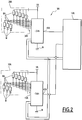
- the calibrator 16A illustrated in more detail at figure 2 , comprises a first 28A and respectively a second 30A storage members of first, respectively second predetermined identifiers.
- the calibration member 16A also comprises a first 32A and respectively a second 34A reading members of the first, respectively second predetermined identifiers.
- the first and respectively second reading devices 32A, 34A are associated with the first 28A and respectively with the second 30A storage devices.
- the first calibrator 16A is, for example, installed in the first circuit breaker 4A during the manufacture in the factory of the first circuit breaker 4A.
- the trigger device 22A is able to control the opening of the contacts of the first circuit breaker 4A.
- the tripping device 22A comprises, for example, a coil, not shown, adapted to control the opening of the contacts of the first circuit breaker 4A as a function of the current flowing through it.
- the processor 24A is adapted to execute software stored in the memory 26A.
- the memory 26A is suitable for storing software 35A for controlling the trigger device 22A and software 36A for controlling the calibration device 16A.
- the control software 36A is able, when it is executed by the processor 24A, to generate a command to read the first and second predetermined identifiers and to transmit the generated read command to each reader 32A, 34A.
- the memory 26A is also suitable for storing a software 37A for determining calibration data as a function of the first and of the second identifier. predetermined.
- the calibration data define at least one condition for controlling the opening of the contacts of the circuit breaker 4A by the trip unit 22A.
- the calibration data correspond, for example, to a rated current of the first circuit breaker 4A determined as a function of the first identifier, and to a breaking capacity of the first circuit breaker 4A determined as a function of the second identifier.
- the rated current is the current that the 4A circuit breaker is able to withstand under specified conditions of continuous service tests while respecting temperature rise limits.
- the breaking capacity corresponds to a maximum intensity of a current that the first 4A circuit breaker is able to interrupt without deteriorating.
- the memory 26A is, moreover, able to store a predetermined datum D corresponding to a configuration of the first circuit breaker 4A.
- the data item D is, for example, suitable for taking a first or a second predetermined value each corresponding to a respective configuration of the first circuit breaker 4A.
- the first value corresponds to a digital configuration, corresponding to the fact that each predetermined identifier is stored by the storage devices 28A, 30A in a digital format.
- the second predetermined value corresponds to an analog configuration, corresponding to the fact that each predetermined identifier is stored by storage units 28B, 30B in an analog format.
- the first storage device 28A is suitable for storing the first predetermined identifier, according to which the trip unit 14A is able to control the opening of the contacts of the circuit breaker 4A.
- the first storage device 28A is electrically connected to inputs 38A of the first reading device 32A.
- the second storage device 30A is suitable for storing the second predetermined identifier, according to which the trip unit 14A is able to control the opening of the contacts of the circuit breaker 4A.
- the second storage device 30A is electrically connected to inputs 40A of the second reading device 34A.
- the first 28A and second 30A storage members comprise resistors RA each connected on the one hand, either to an electronic ground M, or to a predetermined potential VA different from the ground and, on the other hand, to one of the inputs. 38A, 40A of the first 32A, respectively second 34A, reading members. Each resistor RA is connected to a different input of the first 32A or second 34A reading member.
- the resistor RA connected to said input is connected, for example by an operator, at the predetermined potential VA.
- the resistor RA connected to said input is connected to ground M.
- each storage unit 28A, 30A comprises eight resistors RA, three of which are connected to ground M and five to the predetermined potential VA, to encode and memorize the first and the second predetermined identifier, each on 8 bits.
- Each stored predetermined identifier comprises, at the input of the corresponding reader 32A, 34A, at least one data bit and at least one verification bit, and more specifically in the example of figure 2 , five data bits and three check bits, such as cyclic redundancy check bits.
- each predetermined identifier comprises a first number of verification bits greater than or equal to 2, preferably equal to 3.
- the first 32A and second 34A read units include shift registers. These read units 32A, 34A are preferably shift registers, such as parallel-series shift registers, each comprising eight inputs 38A, 40A in parallel and a single output 41A, 42A connected in series to the trigger unit. 14A.
- shift registers such as parallel-series shift registers, each comprising eight inputs 38A, 40A in parallel and a single output 41A, 42A connected in series to the trigger unit. 14A.
- Readers 32A, 34A are adapted to, in response to the transmission of the read command, read the first and second predetermined identifiers and send them to the trigger unit 14A.
- the read command corresponds to a read command of the first and second identifiers.
- Each shift register comprises a set of synchronous flip-flops, not shown, also called logic circuits, controlled via the read command.
- An output of each flip-flop is for example connected to the input of the next flip-flop.
- a piece of data introduced into a first flip-flop propagates according to a clock signal, depending on the read command, in one or more following flip-flops.
- the first reading member 32A is adapted to store the first identifier temporarily only when it is electrically powered.
- the second reading member 34A is adapted to store the second identifier temporarily only when it is electrically powered.
- the reading devices 32A, 34A are suitable for simultaneously receiving the reading command.
- the reading units 32A, 34A are adapted to, in response to the transmission of the read command, read the first predetermined identifier, respectively the second predetermined identifier and send to the trigger unit 14A the first, respectively second predetermined identifiers read. .
- the reading members 32A, 34A, and therefore the calibration member 16A are adapted to, in response to the transmission of the read command for each predetermined identifier, read each predetermined identifier stored in each storage unit 28A, 30A and sending to the trigger unit 14A, via the outputs 41A, 42A, each predetermined identifier read, within a period of less than 300 ⁇ s, preferably less than 200 ⁇ s.
- the 35A tripping device piloting software is suitable for, when executed by the 24A processor, controlling the opening of the circuit breaker contacts, according to the calibration data (s) and the measured current value. by the measuring device 18A.
- the 35A control software is, for example, suitable for defining the current flowing through a coil of the triggering device 22A to control the opening of the contacts of the circuit breaker 4A when the value of the measured current is greater than one of the data of calibration.
- the control software 36A of the calibration member 16A is suitable for, when it is executed by the processor 24A, generating the read command, then transmitting the generated read command to each reading member 32A, 34A.
- the read command is preferably a predetermined command stored in memory 26A.
- the control software 36A is suitable for being executed by the processor 24A, and for generating the read command, then transmitting the generated read command, only when the current measured by the current measuring device 18A is greater than a value.
- predetermined current threshold The control software 36A is, for example, able to generate the read command after waiting for a predetermined time, of the order of 10 ⁇ s, after the measuring device 18A has measured a current of intensity greater than the current threshold value or more generally after the electronic trip unit 14A has been supplied by any power source allowing its operation.
- the current threshold value corresponds to a minimum current value allowing the supply and operation of the trip unit 14A and the calibration device 16A.
- the current threshold value is by example equal to 10% of a value of a minimum current triggering the opening of the contacts of the first 4A circuit breaker.
- a first signal S1 internal to the trigger unit 14A goes from a low logic state to a high logic state, when the value of the intensity of the measured current is greater than the current threshold value or more generally when the 14A trip unit is correctly powered in order to operate. This makes it possible to indicate to the triggering unit, and in particular to the processor 26A, that the power supply to the triggering unit 14A is sufficient for the generation of the read command.
- control software 36A is suitable for reading the predetermined datum D, and modifying the read command if the predetermined datum does not correspond to the digital configuration, that is to say to the first predetermined value.
- data D corresponds to the digital configuration and the read command remains unchanged.
- the control software 36A is also suitable for verifying, as a function of the verification bit (s), the validity of the data bit (s) read and sent by each read unit 32A, 34A to the trigger unit 14A.
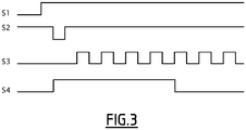
- the control software 36A is suitable for generating the read command which, as shown in figure 3 , comprises a second signal S2 and a third signal S3.
- the second signal S2 is able to cause the loading, in the first 32A, respectively second 34A, reading devices, of the first, respectively second, predetermined identifiers, and of their eight bits present on the inputs 38A, 40A, when they pass. from a high logic state to a low logic state for a given period, of the order for example of 10 ⁇ s.
- the control software 36A is able to generate the second signal S2 and to change the second signal S2 from the high logic state to the low logic state, when the first internal signal S1 passes, for example, from a state logic low to a logic high state.
- each read device is able to send to the trigger unit, via the corresponding output 41A, 42A, a most significant bit of the first, respectively second, predetermined identifiers .
- the control software 36A is able to generate the third signal S3 with a succession of 7 cycles of duration, for example, equal.
- the seven cycles can be assimilated to a clock signal and have a period for example equal to 20 ⁇ s.
- the seven cycles allow the first, respectively second, reading devices 32A, 34A to successively transmitting, on their corresponding output 41A, 42A, the 7 bits of the first and second predetermined identifiers which follow the most significant bit.
- the third signal S3 is suitable for timing the transmission of each bit of the predetermined identifiers on the outputs 41A, 42A of each reading device 32A, 34A.
- Each serial output 41A, 42A is thus able to successively transmit the 8 bits of the predetermined identifier read to the trigger unit 14A.
- the determination software 37A is able, when it is executed by the processor 24A, to associate with each predetermined identifier the corresponding calibration datum.
- a fourth signal S4 represents the state of the output 41A of the first reading member 32A during the transmission of the read command to the first reading member 32A. It is observed that each bit of the first predetermined identifier is successively transmitted to the trigger unit 14A.
- the second circuit breaker 4B is connected between, on the one hand, a first 6B and a second 8B electrical input conductors and, on the other hand, a first 10B and a second 12B output electrical conductors.
- the second circuit breaker 4B comprises contacts, not shown, movable between an open position and a closed position.
- the second circuit breaker 4B comprises an electronic tripping unit 14B, a member 16B for calibrating the electronic tripping unit 14B and a first 28B, and respectively a second 30B, storage members of a first, respectively of a second, predetermined identifiers.
- the tripping unit 14B comprises a member 18B for measuring the current flowing through the second circuit breaker 4B, a member 22B for tripping the opening of the contacts, a processor 24B and a memory 26B associated with the processor 24B.
- the calibrator 16B illustrated in detail at figure 4 , comprises a first 32B, and respectively a second 34B, read devices of the first, and respectively second, predetermined identifiers.
- the calibration member 16B also comprises an adaptation member 31B receiving as input, for each first storage device, the predetermined identifier, and connected at the output to inputs 38B, 40B of the first 32B and second 34B reading devices.
- the processor 24B is adapted to execute software stored by the memory 26B.
- the memory 26B is similar to the memory 26A described above, and is suitable for storing a software 35B for controlling the triggering device, a software 36B for controlling the calibration device 16B and a software 37B for determining d. 'one or more calibration data.
- the memory 26B is also able to store the predetermined datum D corresponding to the configuration of the second circuit breaker 4B.
- the control software 36B is able, when it is executed by the processor 24B, to generate a read command and to transmit to each reader 32B, 34B the generated read command.
- the first storage device 28B is suitable for storing a first predetermined identifier, according to which the trip unit 14B is able to control the opening of the contacts of the circuit breaker 4B.
- the second storage device 30B is suitable for storing a second predetermined identifier, according to which the tripping unit 14B is able to control the opening of the contacts of the circuit breaker 4B.
- the first 28B and second 30B storage members are electrically connected to inputs E of the adaptation member 31B.
- the first 28B and second 30B storage members are, for example, installed in the circuit breaker during its manufacture in the factory.
- the first 28B and second 30B storage members comprise resistors RB of adjustable values, supplied with voltage via the predetermined potential VA when the contacts of the circuit breaker 4B are closed or when the electronic trip unit 14B is supplied by a power source. arbitrary, and suitable for varying an electrical quantity transmitted to the adaptation member 31B.
- the resistors RB of each storage unit 28B, 30B are connected to each other between the electrical ground M and the predetermined potential.
- the predetermined identifiers are thus stored by the first 28B and second 30B storage members in the form of an electrical quantity, such as a voltage, that is to say in an analog format.
- the first storage device 28B comprises two adjustable resistors RB, while the second storage device 30B comprises three adjustable resistors RB.
- the adaptation member 31B receives on its inputs, for each first 28B, respectively second 30B, storage member, the electrical quantity corresponding to the first, respectively second, predetermined identifiers.
- the adaptation member 31B is adapted to supply to the first 32B and second 34B reading units on their respective inputs 38B, 40B, the first, respectively second, predetermined identifiers in a predetermined digital format.
- the adaptation member 31B is suitable, for each storage member 28B, 30B, to provide to one of the reading members 32B, 34B, on the inputs of the reading member 32B, 34B, the predetermined identifier which comprises a second number of check bits less than or equal to the first number of check bits of each identifier predetermined in the first circuit breaker 4A, that is to say in the calibration member 16A.
- the second number of check bits is preferably equal to 1.
- Each predetermined identifier comprises, according to its predetermined digital format, at the input of the corresponding reader 32B, 34B, at least one data bit and at least one verification bit, and more specifically in the example of figure 5 , five data bits and a check bit, such as a parity bit.
- the adaptation member 31B is adapted to, in response to the transmission of the read command, convert the first and second predetermined identifiers into the predetermined digital format.
- the adaptation member 31B comprises analog-to-digital converters 45B adapted to convert the electrical quantities into digital quantities.
- the adaptation unit 31B also comprises a conversion unit 46B, such as a programmable logic circuit, connected to outputs 44B of the converters 45B, and adapted to transmit to the reading units 32B, 34B, the predetermined identifiers in the format predetermined digital, following the transmission of the read command to the calibration member 16B.
- the reading members 32B, 34B are adapted to, in response to the transmission of the read command, read the first and second predetermined identifiers and send the first and second identifiers to the trigger unit 14B. predetermined read.
- the reading devices 32B, 34B are suitable for simultaneously receiving the reading command.
- the reading members 32B, 34B are adapted to, in response to the transmission of the read command, simultaneously read the first predetermined identifier, respectively the second predetermined identifier, transmitted by the adaptation member 31B and send to the unit trigger 14B, the first, respectively second, identifiers.
- the calibrator 16B is adapted to, in response to the transmission of the command to read each predetermined identifier, read each predetermined identifier and send to the trigger unit 14B each identifier within a period of less than 300 ⁇ s, preferably less than 200 ⁇ s.
- control software 36B is suitable for being executed by the processor 24B, and for generating the read command and then transmitting the generated read command, when the current measured by the measuring device of the current 18B is greater than a predetermined current threshold value or, more generally, when the trigger unit 14B is electrically supplied.
- the read command generated and transmitted then corresponds to that presented in the first embodiment.
- the control software 36B is able to read the predetermined datum D.
- the predetermined datum D corresponds to the analog configuration, which is the case for the second circuit breaker 4B
- the control software 36B is able to modify the read command transmitted to the calibration member 16B.
- the read command is modified to restart the reading of each predetermined identifier.
- the trigger unit 14B is suitable for transmitting the read command and recovering information transmitted by the reading devices, while the analog-to-digital converters 45B do not necessarily transmit stable digital quantities to the conversion device. 46B.
- the predetermined time is for example equal to 40 ⁇ s.
- the read command is changed to control the reading of the five data bits and the check bit.
- the transmission time of the predetermined identifiers to the trigger unit 14B, following the generation of the read command, is the same in the first and in the second embodiment. Indeed, the fact that in the second embodiment, the number of bits to be read at the input of the read devices is lower than in the first embodiment, makes it possible to reduce the number of bits to be read in the second embodiment. and therefore taking into account the predetermined time.
- circuit breakers 4A and 4B will now be presented using the figure 5 presenting a method for calibrating the tripping unit 14A, 14B of the first 4A and second 4B circuit breakers.
- the memory 26A, 26B stores the predetermined data item D.
- the predetermined datum is, for example, supplied by the operator to the memory 26A, 26B via a datum input operation D.
- the control software generates the read command and transmits the generated read command to the calibration member 16A, 16B.
- the read command is, for example, generated when the measuring device 18A, 18B measures a current whose intensity is greater than the predetermined threshold value or, more generally, when the trigger unit 14A , 14B is supplied by any power source.
- the read command is then transmitted to the calibration member 16A, 16B.
- a first reading step 104 the calibration member 16A, 16B and, more precisely, the reading members 32A, 32B, 34A, 34B read the predetermined identifiers and send the first and second identifiers read to the reader.
- trigger unit 14A, 14B depending on the read command and in response to the read command.
- the trigger unit 14A, 14B then receives the bits forming the predetermined identifiers.
- the first reading step 104 and the generation step 102 take place in parallel for a predetermined period of less than 300 ⁇ s, preferably at 200 ⁇ s.
- control software 36A, 36B performs a recovery step 106, during which it recovers the predetermined datum D in the memory 26A, 26B and identifies the predetermined datum D recovered.
- the control software knows the type of circuit breaker configuration 4A, 4B.
- the read command remains unchanged and corresponds to a predetermined read command, for example stored in the memory 26A.
- the steps of generation 102 and of reading 104 are then executed until all the bits of the first and second identifiers have been transmitted to the trigger unit 14A, 14B.
- the control software 36B performs a modification step 108, during which the read command is modified as than presented previously. Parameters making it possible to carry out this modification are, for example, stored in the memory 26B.
- the control software 36A, 36B transmits the modified read command to the calibration unit 14A, 14B.
- the reading units 32A, 32B, 34A, 34B read the first and second identifiers and send the first and second predetermined identifiers read to the trigger unit 14A, 14B, depending on of the modified read command and in response to the modified read command.
- a verification step 114 is performed.
- the control software verifies, for each predetermined identifier, the validity of the data bits read and transmitted by the reading devices, as a function of the verification bit (s) read and transmitted by the devices. of readings 32A, 34A, 32B, 34B.
- control software 36A, 36B detects that the data bits sent by one of the read devices 32A, 34A, 32B, 34B are not valid or are erroneous, then the control software 36A, 36B sets the value of the five data bits of the predetermined identifier concerned equal to a fault value and transmits the data bits to the determination software 37A, 37B.
- control software 36A, 36B detects that the data bits transmitted by the read devices 32A, 34A, 32B, 34B are valid, then the control software 36A, 36B transmits to the software for determining 37A, 37B the five data bits of the first and second identifiers.
- the determination software 37A, 37B associates, with the five data bits corresponding to the first identifier, a first calibration datum, and with the five corresponding data bits, with the second identifier a second datum. calibration.
- control software 35A, 35B and the tripping device 22A, 22B then control, during a control step 118, the opening of the circuit breaker according to the calibration data and the current measured by the measuring device. 18A, 18B.
- the calibration members 16A, 16B make it possible to transmit the predetermined identifiers in a reliable and rapid manner to the trigger unit 14A, 14B.
- the trigger unit is thus able to determine the calibration data as a function of the predetermined identifiers in a reliable and rapid manner.
- the safety of an electrical installation comprising circuit breakers 4A, 4B fitted with such calibration devices is thus improved, in particular when closing the mobile contacts of the circuit breaker on a short circuit.
- the calibrators 16A, 16B when they are driven by the trigger unit 14A, 14B, have an identical response time to the read command.
- the calibrator 16B of the second circuit breaker 4B is intended to be installed on existing circuit breakers, comprising devices for memorizing predetermined identifiers in an analog format and in which the reliability and speed of the transmission of predetermined identifiers are thus improved.
- the 16A calibrator is intended to be installed in a circuit breaker such as the first 4A circuit breaker. It improves the reliability and speed of the transmission of predetermined identifiers to the trigger unit 14A.
- the read units 32A, 34A, 32B, 34B are series-series or series-parallel or even parallel-parallel shift registers.
- Each predetermined identifier is a parameter associated with one of the circuit breakers 4A, 4B, for example a parameter relating to a value of the opening rating of the contacts of the circuit breaker 4A, 4B.
Landscapes
- Driving Mechanisms And Operating Circuits Of Arc-Extinguishing High-Tension Switches (AREA)
- Emergency Protection Circuit Devices (AREA)
Claims (11)
- Ausschalter (4A, 4B), welcher eine elektronische Einheit (14A, 14B) zum Auslösen und ein Organ (16A, 16B) zum Kalibrieren der elektronischen Einheit zum Auslösen (14A, 14B) aufweist, wobei die Einheit zum Auslösen (14A, 14B) aufweist ein Organ (22A, 22B) zum Auslösen des Öffnens von Kontakten des Ausschalters, Mittel zur Steuerung (35A, 35B) des Organs zum Auslösen (22A, 22B) und Mittel zum Steuern (36A, 36B) des Organs zum Kalibrieren,wobei das Organ zum Kalibrieren (16A, 16B) aufweist zumindest ein Organ zum Lesen (32A, 34A, 32B, 34B), welches angepasst ist, um den Inhalt von zumindest einem ersten Organ zum Speichern (28A, 30A, 28B, 30B) zu lesen, wobei jedes erste Organ zum Speichern (28A, 30A, 28B, 30B) angepasst ist, um einen vorbestimmten Identifikator zu speichern, wobei jeder vorbestimmte Identifikator ein Parameter ist, welcher mit dem Ausschalter (4A, 4B) assoziiert ist, wobei jedes erste Organ zum Speichern (28A, 30A, 28B, 30B) entweder im Organ zum Kalibrieren (16A, 16B) oder im Ausschalter (4A, 4B) enthalten ist,wobei die Mittel zum Steuern (36A, 36B) des Organs zum Kalibrieren angepasst sind, um einen Befehl zum Lesen jedes vorbestimmten Identifikators zu erzeugen und diesen zu jedem Organ zum Kalibrieren zu übertragen, wobei die Einheit zum Auslösen (14A, 14B) angepasst ist, um das Öffnen der Kontakte des Ausschalters in Abhängigkeit von jedem vorbestimmten Identifikator zu steuern,dadurch gekennzeichnet, dass jedes Organ zum Lesen (32A, 34A, 32B, 34B) ein Schieberegister aufweist, welches angepasst ist, um in Antwort auf das Übertragen des Befehls zum Lesen jeden vorbestimmten Identifikator zu lesen und jeden gelesenen vorbestimmten Identifikator zur Einheit zum Auslösen (14A, 14B) zu senden,wobei jedes Organ zum Lesen (32A, 34A, 32B, 34B) einen oder mehrere Eingänge aufweist, welche jeweils imstande sind, zumindest einen der vorbestimmten Identifikatoren zu empfangen, wobei jeder vorbestimmte Identifikator zumindest ein Datenbit und zumindest ein Verifikationsbit aufweist, wobei jeder Identifikator ein Parameter ist, welcher einen Wert zum Kalibrieren des Auslösens des Öffnens der Kontakte des Ausschalters (4A, 4B) betrifft,wobei die Mittel zum Steuern (36A, 36B) angepasst sind, um in Abhängigkeit von dem oder von den Verifikationsbits die Gültigkeit des oder der Datenbits, welche mittels jedes Organs zum Lesen gelesen und gesendet werden, zu verifizieren.
- Ausschalter (4A, 4B) gemäß Anspruch 1, wobei jedes Schieberegister eine Anordnung mit synchronen Flipflops aufweist, welche via den Befehl zum Lesen gesteuert werden.
- Ausschalter (4A, 4B) gemäß einem der vorherigen Ansprüche, wobei jedes Organ zum Lesen (32A, 34A, 32B, 34B) mit einem korrespondierenden ersten Organ zum Speichern (28A, 30A, 28B, 30B) verbunden ist und angepasst ist, um den Identifikator auf vorübergehende Weise zu speichern, nur wenn es elektrisch versorgt wird.
- Ausschalter (4A, 4B) gemäß einem der vorherigen Ansprüche, wobei das Organ zum Kalibrieren angepasst ist, um in Antwort auf das Übertragen des Befehls zum Lesen jedes vorbestimmten Identifikators jeden vorbestimmten Identifikator, welcher in jedem ersten Organ zum Speichern (28A, 30A, 28B, 30B) gespeichert ist, zu lesen und zur Einheit zum Auslösen (14A, 14B) jeden gelesenen Identifikator zu senden, in einer Zeitspanne, welche kleiner als 300 µs, vorzugsweise kleiner als 200 µs, ist.
- Ausschalter (4A) gemäß einem der vorherigen Ansprüche, wobei jedes Organ zum Lesen (32A, 34A) ein parallel-serielles Schieberegister aufweist, welches mehrere parallele Eingänge (38A, 40A) und einen einzigen Ausgang (41A, 42A) aufweist, und wobei das Organ zum Kalibrieren (16A) jedes erste Organ zum Speichern (28A, 30A) aufweist, und jedes erste Organ zum Speichern (28A, 30A) Widerstände (RA) aufweist, welche alle verbunden sind einerseits entweder mit einer elektronischen Masse (M) oder einem vorbestimmten Potential (VA), welches von der Masse verschieden ist, und andererseits mit einem der parallelen Eingänge (38A, 40A) von einem der Schieberegister.
- Ausschalter (4B) gemäß einem der Ansprüche 1 bis 4, welcher jedes erste Organ zum Speichern (32B, 34B) aufweist, wobei jedes erste Organ zum Speichern (32B, 34B) zumindest einen Widerstand (RB) mit einstellbarem Wert aufweist, wobei der vorbestimmte Identifikator zur einer elektrischen Größe korrespondiert, welche mit dem oder den einstellbaren Widerständen (RB) assoziiert ist, wobei das Organ zum Kalibrieren (16B) ein Organ zum Anpassen (31B) aufweist, welches am Eingang, für jedes erste Organ zum Speichern (28B, 30B), die korrespondierende elektrische Größe empfängt und welches angepasst ist, um einem der Organe zum Lesen (32B, 34B) den vorbestimmten Identifikator bereitzustellen.
- Ausschalter (4A, 4B) gemäß einem der vorherigen Ansprüche, wobei das Organ zum Kalibrieren mehrere Organe zum Lesen (32A, 34A, 32B, 34B) aufweist, wobei jedes mit einem unterschiedlichen ersten Organ zum Speichern (28A, 30A, 28B, 30B) assoziiert ist.
- Gruppe (2) mit zumindest zwei Ausschaltern (4A, 4B), welche zumindest aufweist:- einen ersten Ausschalter (4A) gemäß Anspruch 5, wobei jedes erste Organ zum Speichern (28A, 30A) angepasst ist, um den vorbestimmten Identifikator zu speichern, welcher eine erste vorbestimmte Anzahl an Verifikationsbits aufweist, welche größer oder gleich 2, vorzugsweise gleich 3, ist, und- einen zweiten Ausschalter (4B) gemäß Anspruch 6, wobei das Organ zum Anpassen (31 B) imstande ist, für jedes erste Organ zum Speichern (28A, 30B), einem der Organe zum Lesen (32B, 34B) den vorbestimmten Identifikator bereitzustellen, welcher eine zweite Anzahl an Verifikationsbits aufweist, welche kleiner oder gleich der ersten Anzahl an Verifikationsbits jedes vorbestimmten Identifikators im ersten Ausschalter (4A) ist, wobei die zweite Anzahl an Verifikationsbits verzugsweise gleich 1 ist.
- Ausschalter (4A, 4B) gemäß irgendeinem der Ansprüche 1 bis 7, wobei die elektronische Einheit zum Auslösen (14A, 14B) Mittel zum Ermitteln (37A, 37B) aufweist, welche imstande sind, mit jedem vorbestimmten Identifikator, welcher mittels jedes Organs zum Lesen (32A, 34A, 32B, 34B) gesendet wird, ein Kalibrierung-Datenelement zu assoziieren, wobei das oder die Kalibrierung-Datenelemente zumindest eine Bedingung zum Steuern des Öffnens der Kontakte des Ausschalters (4A, 4B) definieren und die Mittel zur Steuerung (35A, 35B) angepasst sind, um das Öffnen der Kontakte in Abhängigkeit von dem oder von den Kalibrierung-Datenelementen zu steuern.
- Verfahren zum Kalibrieren einer elektronischen Einheit zum Auslösen (14A, 14B) eines Ausschalters (4A, 4B) mittels eines Organs zum Kalibrieren (16A, 16B), wobei die Einheit zum Auslösen (14A, 14B) aufweist ein Organ zum Auslösen (22A, 22B) des Öffnens von Kontakten des Ausschalters und Mittel zur Steuerung (35A, 35B) des Organs zum Auslösen (22A, 22B), wobei das Organ zum Kalibrieren (16A, 16B) zumindest ein Organ zum Lesen (32A, 34A, 32B, 34B) aufweist, welches angepasst ist, um den Inhalt von zumindest einem ersten Organ zum Speichern (28A, 30A, 28B, 30B) zu lesen, wobei jedes erste Organ zum Speichern (28A, 30A, 28B, 30B) angepasst ist, um einen vorbestimmten Identifikator zu speichern, wobei jeder vorbestimmte Identifikator ein Parameter ist, welcher mit dem Ausschalter (4A, 4B) assoziiert ist, wobei jedes erste Organ zum Speichern (28A, 30A, 28B, 30B) entweder im Organ zum Kalibrieren (16A, 16B) oder im Ausschalter (4A, 4B) enthalten ist,wobei das Verfahren die folgenden Schritte aufweist:- a) das Erzeugen (102) eines Befehls zum Lesen jedes vorbestimmten Identifikators,- b) das Übertragen (102) des Befehls zum Lesen zum Organ zum Kalibrieren,- d) das Steuern (118) des Öffnens der Kontakte des Ausschalters in Abhängigkeit von jedem vorbestimmten Identifikator,dadurch gekennzeichnet, dass das Organ zum Lesen (32A, 34A, 32B, 34B) ein Schieberegister aufweist, und dadurch, dass das Verfahren vor dem Schritt des Steuerns (118) die folgenden Schritte aufweist:- b') das Lesen (104) mittels des oder der Organe zum Lesen (32A, 34A, 32B, 34B) jedes vorbestimmten Identifikators und- b") das Senden (104) zur Einheit zum Auslösen (14A, 14B) jedes vorbestimmten Identifikators, welcher während des Schritts b') gelesen wird,wobei jedes Organ zum Lesen (32A, 34A, 32B, 34B) einen oder mehrere Eingänge aufweist, welche jeweils imstande sind, zumindest einen der vorbestimmten Identifikatoren zu empfangen, wobei jeder vorbestimmte Identifikator zumindest ein Datenbit und zumindest ein Verifikationsbit aufweist, wobei jeder Identifikator ein Parameter ist, welcher einen Wert zum Kalibrieren des Auslösens des Öffnens der Kontakte des Ausschalters (4A, 4B) betrifft,wobei das Verfahren im Anschluss an den Schritt des Sendens (104) und vor dem Schritt des Steuerns (118) den folgenden Schritt aufweist:- c) das Verifizieren (114) in Abhängigkeit von dem oder von den Verifikationsbits der Gültigkeit des oder der Datenbits, welche mittels jedes Organs zum Lesen gelesen und gesendet werden.
- Verfahren gemäß Anspruch 10, wobei die Schritte des Lesens (104) und des Übertragens (102) während einer vorbestimmten Dauer parallel stattfinden und das Verfahren vor dem Schritt des Erzeugens (102) den folgenden Schritt aufweist:- das Speichern (100) in der Einheit zum Auslösen (14A, 14B) eines vorbestimmten Datenelements (D), welches zu einer Konfiguration des Ausschalters korrespondiert,und das Verfahren während des Schritts des Lesens die folgenden Schritte aufweist:- das Wiedererlangen (106) des vorbestimmten Datenelements,- das Modifizieren (108) des Befehls zum Lesen in Abhängigkeit von dem vorbestimmten Datenelement, wobei der Befehl zum Lesen modifiziert wird, um das Lesen jedes vorbestimmten Identifikators wieder zu beginnen, wenn das vorbestimmte Datenelement gleich einem vorbestimmten Wert ist.
Priority Applications (1)
| Application Number | Priority Date | Filing Date | Title |
|---|---|---|---|
| PL15172534T PL2961018T3 (pl) | 2014-06-24 | 2015-06-17 | Urządzenie do kalibracji elektronicznej jednostki wyzwalającej wyłącznika, zespół takich urządzeń do kalibracji, wyłącznik i powiązany sposób kalibracji |
Applications Claiming Priority (1)
| Application Number | Priority Date | Filing Date | Title |
|---|---|---|---|
| FR1455842A FR3022704B1 (fr) | 2014-06-24 | 2014-06-24 | Organe de calibrage d'une unite electronique de declenchement d'un disjoncteur, ensemble de tels organes de calibrage, disjoncteur, et procede de calibrage associes |
Publications (2)
| Publication Number | Publication Date |
|---|---|
| EP2961018A1 EP2961018A1 (de) | 2015-12-30 |
| EP2961018B1 true EP2961018B1 (de) | 2021-09-22 |
Family
ID=51298867
Family Applications (1)
| Application Number | Title | Priority Date | Filing Date |
|---|---|---|---|
| EP15172534.8A Active EP2961018B1 (de) | 2014-06-24 | 2015-06-17 | Eichorgan einer elektronischen einheit zum auslösen eines schutzschalters, gesamtheit dieser eichorgane, entsprechender schutzschalter und entsprechendes eichverfahren |
Country Status (4)
| Country | Link |
|---|---|
| EP (1) | EP2961018B1 (de) |
| ES (1) | ES2896758T3 (de) |
| FR (1) | FR3022704B1 (de) |
| PL (1) | PL2961018T3 (de) |
Family Cites Families (3)
| Publication number | Priority date | Publication date | Assignee | Title |
|---|---|---|---|---|
| US4788620A (en) * | 1987-11-09 | 1988-11-29 | General Electric Company | Static trip circuit breaker with automatic circuit trimming |
| US5506485A (en) * | 1992-08-21 | 1996-04-09 | Eaton Corporation | Digital modular microprocessor based electrical contactor system |
| CA2205102A1 (en) * | 1996-05-13 | 1997-11-13 | Eaton Corporation | Electrical apparatus having programmable settings provided by a single dip switch and a multiposition selector switch |
-
2014
- 2014-06-24 FR FR1455842A patent/FR3022704B1/fr not_active Expired - Fee Related
-
2015
- 2015-06-17 EP EP15172534.8A patent/EP2961018B1/de active Active
- 2015-06-17 PL PL15172534T patent/PL2961018T3/pl unknown
- 2015-06-17 ES ES15172534T patent/ES2896758T3/es active Active
Also Published As
| Publication number | Publication date |
|---|---|
| EP2961018A1 (de) | 2015-12-30 |
| FR3022704A1 (fr) | 2015-12-25 |
| ES2896758T3 (es) | 2022-02-25 |
| FR3022704B1 (fr) | 2016-07-15 |
| PL2961018T3 (pl) | 2022-02-07 |
Similar Documents
| Publication | Publication Date | Title |
|---|---|---|
| EP3126783B1 (de) | Vorrichtung zur messung von mindestens einer physikalischen grösse einer elektrischen installation | |
| EP1111508B1 (de) | Integrierte Schaltung mit Kalibriermitteln zur Kalibrierung eines elektronischen Moduls und Verfahren zum Kalibrieren eines elektronischen Moduls in einer Integrierten Schaltung | |
| US9184795B2 (en) | Packet energy transfer in-line communications | |
| EP0504062B1 (de) | Integrierte Schaltung mit servogesteuerten Impedanzen und Anwendung für Senderempfänger, insbesondere für die Kommunikation zwischen Einheiten eines Informationssystems | |
| EP2966454A1 (de) | Verfahren zum Messen eines physikalischen Parameters, und elektronischer Schaltkreis zu dessen Umsetzung | |
| EP0631240A1 (de) | Schaltungsanordnung zur Datenübertragung | |
| FR2480515A1 (fr) | Appareil coupe-circuit a indicateur a distance et a alimentation | |
| WO2016202603A1 (fr) | Systeme d'alimentation electrique pour automate programmable | |
| FR2623012A1 (fr) | Disjoncteur a declenchement statique avec reglage automatique des circuits | |
| EP3545621B1 (de) | Schaltelement für eine leistungsschaltung | |
| FR2674083A1 (fr) | Emetteur-recepteur pour liaison bidirectionnelle, circuit integre l'incorporant et application a la communication entre unites d'un systeme informatique. | |
| EP2927928B1 (de) | Verfahren zur bestimmung einer überhitzung mindestens einer verbindungsklemme einer elektrischen vorrichtung, entsprechendes hilfsgerät und elektrisches system, das eine solche elektrische vorrichtung und ein solches hilfsgerät umfasst | |
| EP2961018A1 (de) | Eichorgan einer elektronischen einheit zum auslösen eines schutzschalters, gesamtheit dieser eichorgane, entsprechender schutzschalter und entsprechendes eichverfahren | |
| EP3451361B1 (de) | Elektrische schaltvorrichtung und entsprechende konfigurations- und diagnoseverfahren | |
| FR2749083A1 (fr) | Agencement pour le controle de la charge d'un ensemble modulaire de cellules electrochimiques raccordees en serie et module correspondant de mesure pour cellule | |
| EP1291817B1 (de) | Nachweis von Umgebungsvariationen in einer Integrierten Schaltung | |
| FR3065089B1 (fr) | Procede de commande d'un appareil de coupure de courant electrique, actionneur electromagnetique comprenant un circuit de mise en oeuvre de ce procede et appareil electrique de coupure comprenant un tel actionneur | |
| EP2993962B1 (de) | Vorrichtung zur übertragung eines elektrischen signals zur parametrisierung eines überwachungsorgans eines beleuchtungsmoduls mit elektrolumineszenzdioden, entsprechendes stromversorgungssystem, entsprechende beleuchtungsanordung und entsprechendes übertragungsverfahren | |
| EP3552034B1 (de) | Verfahren zur herstellung eines messsensors für einen leistungsschalter | |
| FR2483142A1 (fr) | Piece d'horlogerie electronique comportant un circuit de controle du moteur | |
| EP2693585B1 (de) | Schutzsystem für eine Vielzahl von elektrischen Ableitungen gegen Kurzschlüsse, und Elektroanlage, die ein solches Schutzsystem umfasst | |
| WO2024209145A1 (fr) | Système et méthode de protection d'un système électronique d'actionnement contre un sur-courant | |
| EP3159704B1 (de) | Messkette für eine elektronische signalschaltung | |
| FR2916873A1 (fr) | Dispositif de controle de communication entre un module et un bus de transmission | |
| EP0594478B1 (de) | Anwendungsspezifische Integrierte Schaltung mit einem Mikroprozessor und Prüfmitteln |
Legal Events
| Date | Code | Title | Description |
|---|---|---|---|
| PUAI | Public reference made under article 153(3) epc to a published international application that has entered the european phase |
Free format text: ORIGINAL CODE: 0009012 |
|
| AK | Designated contracting states |
Kind code of ref document: A1 Designated state(s): AL AT BE BG CH CY CZ DE DK EE ES FI FR GB GR HR HU IE IS IT LI LT LU LV MC MK MT NL NO PL PT RO RS SE SI SK SM TR |
|
| AX | Request for extension of the european patent |
Extension state: BA ME |
|
| 17P | Request for examination filed |
Effective date: 20160614 |
|
| RBV | Designated contracting states (corrected) |
Designated state(s): AL AT BE BG CH CY CZ DE DK EE ES FI FR GB GR HR HU IE IS IT LI LT LU LV MC MK MT NL NO PL PT RO RS SE SI SK SM TR |
|
| STAA | Information on the status of an ep patent application or granted ep patent |
Free format text: STATUS: EXAMINATION IS IN PROGRESS |
|
| 17Q | First examination report despatched |
Effective date: 20200124 |
|
| GRAP | Despatch of communication of intention to grant a patent |
Free format text: ORIGINAL CODE: EPIDOSNIGR1 |
|
| STAA | Information on the status of an ep patent application or granted ep patent |
Free format text: STATUS: GRANT OF PATENT IS INTENDED |
|
| INTG | Intention to grant announced |
Effective date: 20210504 |
|
| GRAS | Grant fee paid |
Free format text: ORIGINAL CODE: EPIDOSNIGR3 |
|
| GRAA | (expected) grant |
Free format text: ORIGINAL CODE: 0009210 |
|
| STAA | Information on the status of an ep patent application or granted ep patent |
Free format text: STATUS: THE PATENT HAS BEEN GRANTED |
|
| AK | Designated contracting states |
Kind code of ref document: B1 Designated state(s): AL AT BE BG CH CY CZ DE DK EE ES FI FR GB GR HR HU IE IS IT LI LT LU LV MC MK MT NL NO PL PT RO RS SE SI SK SM TR |
|
| REG | Reference to a national code |
Ref country code: GB Ref legal event code: FG4D Free format text: NOT ENGLISH |
|
| REG | Reference to a national code |
Ref country code: DE Ref legal event code: R096 Ref document number: 602015073460 Country of ref document: DE |
|
| REG | Reference to a national code |
Ref country code: IE Ref legal event code: FG4D Free format text: LANGUAGE OF EP DOCUMENT: FRENCH |
|
| REG | Reference to a national code |
Ref country code: CH Ref legal event code: EP Ref country code: AT Ref legal event code: REF Ref document number: 1433053 Country of ref document: AT Kind code of ref document: T Effective date: 20211015 |
|
| REG | Reference to a national code |
Ref country code: NL Ref legal event code: FP |
|
| REG | Reference to a national code |
Ref country code: LT Ref legal event code: MG9D |
|
| PG25 | Lapsed in a contracting state [announced via postgrant information from national office to epo] |
Ref country code: SE Free format text: LAPSE BECAUSE OF FAILURE TO SUBMIT A TRANSLATION OF THE DESCRIPTION OR TO PAY THE FEE WITHIN THE PRESCRIBED TIME-LIMIT Effective date: 20210922 Ref country code: RS Free format text: LAPSE BECAUSE OF FAILURE TO SUBMIT A TRANSLATION OF THE DESCRIPTION OR TO PAY THE FEE WITHIN THE PRESCRIBED TIME-LIMIT Effective date: 20210922 Ref country code: HR Free format text: LAPSE BECAUSE OF FAILURE TO SUBMIT A TRANSLATION OF THE DESCRIPTION OR TO PAY THE FEE WITHIN THE PRESCRIBED TIME-LIMIT Effective date: 20210922 Ref country code: NO Free format text: LAPSE BECAUSE OF FAILURE TO SUBMIT A TRANSLATION OF THE DESCRIPTION OR TO PAY THE FEE WITHIN THE PRESCRIBED TIME-LIMIT Effective date: 20211222 Ref country code: FI Free format text: LAPSE BECAUSE OF FAILURE TO SUBMIT A TRANSLATION OF THE DESCRIPTION OR TO PAY THE FEE WITHIN THE PRESCRIBED TIME-LIMIT Effective date: 20210922 Ref country code: BG Free format text: LAPSE BECAUSE OF FAILURE TO SUBMIT A TRANSLATION OF THE DESCRIPTION OR TO PAY THE FEE WITHIN THE PRESCRIBED TIME-LIMIT Effective date: 20211222 Ref country code: LT Free format text: LAPSE BECAUSE OF FAILURE TO SUBMIT A TRANSLATION OF THE DESCRIPTION OR TO PAY THE FEE WITHIN THE PRESCRIBED TIME-LIMIT Effective date: 20210922 |
|
| REG | Reference to a national code |
Ref country code: AT Ref legal event code: MK05 Ref document number: 1433053 Country of ref document: AT Kind code of ref document: T Effective date: 20210922 |
|
| REG | Reference to a national code |
Ref country code: ES Ref legal event code: FG2A Ref document number: 2896758 Country of ref document: ES Kind code of ref document: T3 Effective date: 20220225 |
|
| PG25 | Lapsed in a contracting state [announced via postgrant information from national office to epo] |
Ref country code: LV Free format text: LAPSE BECAUSE OF FAILURE TO SUBMIT A TRANSLATION OF THE DESCRIPTION OR TO PAY THE FEE WITHIN THE PRESCRIBED TIME-LIMIT Effective date: 20210922 Ref country code: GR Free format text: LAPSE BECAUSE OF FAILURE TO SUBMIT A TRANSLATION OF THE DESCRIPTION OR TO PAY THE FEE WITHIN THE PRESCRIBED TIME-LIMIT Effective date: 20211223 |
|
| PG25 | Lapsed in a contracting state [announced via postgrant information from national office to epo] |
Ref country code: AT Free format text: LAPSE BECAUSE OF FAILURE TO SUBMIT A TRANSLATION OF THE DESCRIPTION OR TO PAY THE FEE WITHIN THE PRESCRIBED TIME-LIMIT Effective date: 20210922 |
|
| PG25 | Lapsed in a contracting state [announced via postgrant information from national office to epo] |
Ref country code: IS Free format text: LAPSE BECAUSE OF FAILURE TO SUBMIT A TRANSLATION OF THE DESCRIPTION OR TO PAY THE FEE WITHIN THE PRESCRIBED TIME-LIMIT Effective date: 20220122 Ref country code: SK Free format text: LAPSE BECAUSE OF FAILURE TO SUBMIT A TRANSLATION OF THE DESCRIPTION OR TO PAY THE FEE WITHIN THE PRESCRIBED TIME-LIMIT Effective date: 20210922 Ref country code: RO Free format text: LAPSE BECAUSE OF FAILURE TO SUBMIT A TRANSLATION OF THE DESCRIPTION OR TO PAY THE FEE WITHIN THE PRESCRIBED TIME-LIMIT Effective date: 20210922 Ref country code: PT Free format text: LAPSE BECAUSE OF FAILURE TO SUBMIT A TRANSLATION OF THE DESCRIPTION OR TO PAY THE FEE WITHIN THE PRESCRIBED TIME-LIMIT Effective date: 20220124 Ref country code: EE Free format text: LAPSE BECAUSE OF FAILURE TO SUBMIT A TRANSLATION OF THE DESCRIPTION OR TO PAY THE FEE WITHIN THE PRESCRIBED TIME-LIMIT Effective date: 20210922 Ref country code: CZ Free format text: LAPSE BECAUSE OF FAILURE TO SUBMIT A TRANSLATION OF THE DESCRIPTION OR TO PAY THE FEE WITHIN THE PRESCRIBED TIME-LIMIT Effective date: 20210922 Ref country code: AL Free format text: LAPSE BECAUSE OF FAILURE TO SUBMIT A TRANSLATION OF THE DESCRIPTION OR TO PAY THE FEE WITHIN THE PRESCRIBED TIME-LIMIT Effective date: 20210922 |
|
| REG | Reference to a national code |
Ref country code: DE Ref legal event code: R097 Ref document number: 602015073460 Country of ref document: DE |
|
| PG25 | Lapsed in a contracting state [announced via postgrant information from national office to epo] |
Ref country code: DK Free format text: LAPSE BECAUSE OF FAILURE TO SUBMIT A TRANSLATION OF THE DESCRIPTION OR TO PAY THE FEE WITHIN THE PRESCRIBED TIME-LIMIT Effective date: 20210922 |
|
| PLBE | No opposition filed within time limit |
Free format text: ORIGINAL CODE: 0009261 |
|
| STAA | Information on the status of an ep patent application or granted ep patent |
Free format text: STATUS: NO OPPOSITION FILED WITHIN TIME LIMIT |
|
| 26N | No opposition filed |
Effective date: 20220623 |
|
| PG25 | Lapsed in a contracting state [announced via postgrant information from national office to epo] |
Ref country code: SI Free format text: LAPSE BECAUSE OF FAILURE TO SUBMIT A TRANSLATION OF THE DESCRIPTION OR TO PAY THE FEE WITHIN THE PRESCRIBED TIME-LIMIT Effective date: 20210922 |
|
| PG25 | Lapsed in a contracting state [announced via postgrant information from national office to epo] |
Ref country code: MC Free format text: LAPSE BECAUSE OF FAILURE TO SUBMIT A TRANSLATION OF THE DESCRIPTION OR TO PAY THE FEE WITHIN THE PRESCRIBED TIME-LIMIT Effective date: 20210922 |
|
| REG | Reference to a national code |
Ref country code: CH Ref legal event code: PL |
|
| REG | Reference to a national code |
Ref country code: BE Ref legal event code: MM Effective date: 20220630 |
|
| PG25 | Lapsed in a contracting state [announced via postgrant information from national office to epo] |
Ref country code: LU Free format text: LAPSE BECAUSE OF NON-PAYMENT OF DUE FEES Effective date: 20220617 Ref country code: LI Free format text: LAPSE BECAUSE OF NON-PAYMENT OF DUE FEES Effective date: 20220630 Ref country code: IE Free format text: LAPSE BECAUSE OF NON-PAYMENT OF DUE FEES Effective date: 20220617 Ref country code: CH Free format text: LAPSE BECAUSE OF NON-PAYMENT OF DUE FEES Effective date: 20220630 |
|
| PG25 | Lapsed in a contracting state [announced via postgrant information from national office to epo] |
Ref country code: BE Free format text: LAPSE BECAUSE OF NON-PAYMENT OF DUE FEES Effective date: 20220630 |
|
| PG25 | Lapsed in a contracting state [announced via postgrant information from national office to epo] |
Ref country code: HU Free format text: LAPSE BECAUSE OF FAILURE TO SUBMIT A TRANSLATION OF THE DESCRIPTION OR TO PAY THE FEE WITHIN THE PRESCRIBED TIME-LIMIT; INVALID AB INITIO Effective date: 20150617 |
|
| PG25 | Lapsed in a contracting state [announced via postgrant information from national office to epo] |
Ref country code: SM Free format text: LAPSE BECAUSE OF FAILURE TO SUBMIT A TRANSLATION OF THE DESCRIPTION OR TO PAY THE FEE WITHIN THE PRESCRIBED TIME-LIMIT Effective date: 20210922 Ref country code: MK Free format text: LAPSE BECAUSE OF FAILURE TO SUBMIT A TRANSLATION OF THE DESCRIPTION OR TO PAY THE FEE WITHIN THE PRESCRIBED TIME-LIMIT Effective date: 20210922 Ref country code: CY Free format text: LAPSE BECAUSE OF FAILURE TO SUBMIT A TRANSLATION OF THE DESCRIPTION OR TO PAY THE FEE WITHIN THE PRESCRIBED TIME-LIMIT Effective date: 20210922 |
|
| PG25 | Lapsed in a contracting state [announced via postgrant information from national office to epo] |
Ref country code: MT Free format text: LAPSE BECAUSE OF FAILURE TO SUBMIT A TRANSLATION OF THE DESCRIPTION OR TO PAY THE FEE WITHIN THE PRESCRIBED TIME-LIMIT Effective date: 20210922 |
|
| PGFP | Annual fee paid to national office [announced via postgrant information from national office to epo] |
Ref country code: DE Payment date: 20250626 Year of fee payment: 11 Ref country code: PL Payment date: 20250605 Year of fee payment: 11 |
|
| PGFP | Annual fee paid to national office [announced via postgrant information from national office to epo] |
Ref country code: GB Payment date: 20250617 Year of fee payment: 11 |
|
| PGFP | Annual fee paid to national office [announced via postgrant information from national office to epo] |
Ref country code: NL Payment date: 20250624 Year of fee payment: 11 |
|
| PGFP | Annual fee paid to national office [announced via postgrant information from national office to epo] |
Ref country code: FR Payment date: 20250624 Year of fee payment: 11 |
|
| PGFP | Annual fee paid to national office [announced via postgrant information from national office to epo] |
Ref country code: ES Payment date: 20250710 Year of fee payment: 11 |
|
| PGFP | Annual fee paid to national office [announced via postgrant information from national office to epo] |
Ref country code: IT Payment date: 20250623 Year of fee payment: 11 |
|
| PG25 | Lapsed in a contracting state [announced via postgrant information from national office to epo] |
Ref country code: TR Free format text: LAPSE BECAUSE OF FAILURE TO SUBMIT A TRANSLATION OF THE DESCRIPTION OR TO PAY THE FEE WITHIN THE PRESCRIBED TIME-LIMIT Effective date: 20210922 |