EP2962809B1 - Capot protecteur d'une machine-outil electrique, machine-outil electrique et systeme pourvu d'un capot protecteur et de la machine-outil electrique - Google Patents
Capot protecteur d'une machine-outil electrique, machine-outil electrique et systeme pourvu d'un capot protecteur et de la machine-outil electrique Download PDFInfo
- Publication number
- EP2962809B1 EP2962809B1 EP15177840.4A EP15177840A EP2962809B1 EP 2962809 B1 EP2962809 B1 EP 2962809B1 EP 15177840 A EP15177840 A EP 15177840A EP 2962809 B1 EP2962809 B1 EP 2962809B1
- Authority
- EP
- European Patent Office
- Prior art keywords
- protective cover
- blocking
- rotation
- electric power
- power tool
- Prior art date
- Legal status (The legal status is an assumption and is not a legal conclusion. Google has not performed a legal analysis and makes no representation as to the accuracy of the status listed.)
- Expired - Lifetime
Links
- 230000001681 protective effect Effects 0.000 claims description 76
- 230000000903 blocking effect Effects 0.000 claims description 38
- 239000002184 metal Substances 0.000 claims description 2
- 239000000470 constituent Substances 0.000 claims 1
- 238000003780 insertion Methods 0.000 description 9
- 230000037431 insertion Effects 0.000 description 9
- 239000012634 fragment Substances 0.000 description 8
- 230000009172 bursting Effects 0.000 description 5
- 239000002981 blocking agent Substances 0.000 description 3
- 230000009993 protective function Effects 0.000 description 3
- 238000005452 bending Methods 0.000 description 2
- 230000006378 damage Effects 0.000 description 2
- 238000004080 punching Methods 0.000 description 2
- 230000001419 dependent effect Effects 0.000 description 1
- 230000006870 function Effects 0.000 description 1
- 238000009434 installation Methods 0.000 description 1
- 230000002093 peripheral effect Effects 0.000 description 1
- 230000001960 triggered effect Effects 0.000 description 1
Images

Classifications
-
- B—PERFORMING OPERATIONS; TRANSPORTING
- B24—GRINDING; POLISHING
- B24B—MACHINES, DEVICES, OR PROCESSES FOR GRINDING OR POLISHING; DRESSING OR CONDITIONING OF ABRADING SURFACES; FEEDING OF GRINDING, POLISHING, OR LAPPING AGENTS
- B24B55/00—Safety devices for grinding or polishing machines; Accessories fitted to grinding or polishing machines for keeping tools or parts of the machine in good working condition
- B24B55/04—Protective covers for the grinding wheel
- B24B55/05—Protective covers for the grinding wheel specially designed for portable grinding machines
- B24B55/052—Protective covers for the grinding wheel specially designed for portable grinding machines with rotating tools
Definitions
- the invention is based on a protective hood according to the preamble of claim 1.
- a protective hood is made EP 978 353 A known.
- the invention proposes a protective cover according to claim 1.
- the blocking means is formed by an outwardly projecting blocking lug on the protective hood, which abuts against a stop, should the guard rotate on a clamping neck in the direction of rotation.
- the Blocking nose welded to the protective cover, glued or screwed.
- the blocking nose can also be retrofitted. Alternatively, this may also be directed inwards at a suitable location.
- the inventive design of the guard can both a security against contact of the insert tool improved; as well as a protective function; be ensured even with a bursting of the insert tool. Now apart flying fragments of the same can no longer rotate the guard so far on the drive shaft that the fragments endanger an operator. A blockage of the twisting of the protective cover in case of damage is independent of a tightening torque of attachment of the guard.
- the blocking agent can be worked inexpensively and inexpensively directly from the sheet metal of the guard.
- the blocking means is formed by a stop cam in a fastening flange which extends substantially parallel to the axis of rotation.
- the protective hood is attached to the flange on the power tool and therefore allows a space-saving and easy-to-use arrangement of the rotation.
- the stop cam can be directed inwards. Likewise, an arrangement with an outwardly directed stop cam is possible. The person skilled in the art will select a suitable arrangement according to the power tool used.
- the blocking agent is formed by a stop cam in a tension band connected to the flange, an increased degree of safety can be obtained with an easily manufactured means.
- the anti-rotation is not dependent on a clamping force, which is given by a tightening torque of a clamping screw with which the strap is mounted on a clamping neck. Even if the clamping screw has been tightened by mistake, the anti-twist protection is effective. If the stop cam encounters a stop, the guard is reliably held in this position.
- the anti-rotation lock is arranged completely inside the protective hood.
- the anti-twist device can be arranged to save space.
- the blocking lug can be arranged on a surface extending substantially perpendicular to the axis of rotation adjacent to a recess for a drive shaft of the insert tool which is to be covered by the protective hood.
- the blocking nose then conveniently does not protrude into the working area of an operator.
- the invention proposes a power tool according to claim 9.
- a rotation of the protective hood about an axis of rotation of the insert tool can be at least limited. This can both a security against contact of the insert tool improved and a protective function can be ensured even with a bursting of the insert tool. Flying fragments of the insert tool can no longer rotate the protective cover so far on the drive shaft that the fragments endanger an operator.
- twisting of the protective hood can be restricted to a narrow angle range or completely prevented.
- a clamping neck has an insertion groove with a limiting groove arranged at an angle thereto, a tightening strap with a stop cam pushed through on the inside can be inserted.
- a twisting of the guard is possible only within the Begrenzungsnut, which limits the angular range of the guard.
- the guard can be mounted in any position within the Begrenzungsnut.
- a blocking lug and / or a stop cam can strike there and the protective hood can be obstructed in an undesired rotational movement.
- the invention further proposes a system of protective hood and power tool according to claim 13.
- the blocking means is formed by an outwardly projecting blocking lug on the protective hood, which abuts against a stop, should the guard rotate on a clamping neck in the direction of rotation.
- the blocking means may be directly part of the protective hood, such as a cam, or may be provided on a fastening, with which the protective hood is connected to the power tool. A twisting of the guard beyond the stop is reliably avoided.
- the safety of the operator can be guaranteed in case of failure.
- the guard can be twisted at most in an angular range, which still ensures the protective function. Installation of the protective hood in a normal for the normal function of the power tool position is not hindered.
- the power tool is designed as an angle grinder whose grinding wheel is at least partially covered with a protective hood.
- the protective hood can no longer be pulled so far away from the fragments in the original direction of rotation that the operator can be hit by fragments.
- the rotation is independent of a torque of attachment of the guard to a collet.
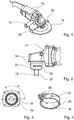
- a power tool in the form of a preferred angle grinder is in Fig. 1 shown.
- a housing 10 an unillustrated electric motor is arranged through which an insert tool 14, here a grinding wheel, is driven in rotation.
- an insert tool 14 here a grinding wheel
- an output shaft of the electric motor is arranged perpendicular to a drive shaft of the insert tool.
- the angle grinder can be held and guided on an angularly projecting handle 12.
- a protective cover 16 covers the insertion tool 14 so far that a contact protection for an operator is ensured.
- the protective hood 16 is designed as a semicircle with a circumferentially projecting, peripheral flange which covers one half of the surface and edge of the grinding wheel 14.
- the protective hood 16 has, for example, a flange 30 projecting centrally in its imaginary circular area and extending essentially parallel to a rotation axis 18 with a tensioning band 26 fastened thereto and is thus fastened to a clamping neck 24 ( Fig. 2-5 ).
- a rotation 20 is provided according to the invention, which at least limits a rotation of the protective cover 16 about an axis of rotation of the insert tool 14 and the clamping neck 24 ,
- Fig. 2 to Fig. 5 show a first preferred embodiment of an anti-rotation device 20.
- a blocking means in the form of a stop cam 32 is provided on the protective hood side, which is formed in a clamping band 26 for fastening a protective hood 16 on the clamping collar 24 and is pressed to the inside of the clamping band 26 ( Fig. 4 ).
- a substantially vertically extending insertion 36 is provided with an angle thereto arranged Begrenzungsnut 34 which forms a stop cam 32 corresponding to the stop means.
- the limiting groove 34 limits a possible rotation about an axis of rotation 18 to an angle range ⁇ (FIG. Fig. 3 ).
- the rotation is independent of a tightening torque of a clamping screw 28, with which the clamping band 26 is tightened around the clamping collar 24 around, blocked by one or the other end of the Begrenzungsnut 34.
- the tension band 26 is more detailed in FIG Fig. 4 shown.
- the clamping band 26 surrounds a protruding from the protective cover 16 flange 30 and clamps the flange 30 of the protective cover 16 on the clamping neck 24 of the drive shaft 22 fixed.
- the stop cam 32 is inserted via the insertion groove 36 into the limiting groove 34.
- the clamping screw 28 is screwed into a screw receptacle 38. By tightening the clamping screw 28, the protective cover 16 can be clamped more or less firmly on the clamping neck 24.
- the limiting groove 34 expediently extends from the insertion groove 36 in the direction of rotation of the insertion tool 14. A rotation of the protective hood 16 is only possible to a maximum extent in the angular range ⁇ over which the limiting groove 34 extends (FIG. Fig. 3 ).
- Fig. 5 shows a plan view of the arrangement.
- an exhaust 44 may be integrated, can be removed with the dusts that arise when working with the insert tool 14.
- the stop cam 32 is pressed on the inside of the tension band 26, with which the protective cover 16 is attached to the clamping neck 24, and projects into the limiting groove 34 of the clamping neck 24.
- FIG. 6 Another preferred embodiment of the anti-rotation device 20 is in Fig. 6 shown.
- a blocking lug 40 is formed on the protective cover 16, which is machined out of the sheet of the protective cover 16 by partial punching and bending.
- the blocking lug 40 may also be welded, glued or screwed.
- the blocking lug 40 projects outwardly from a surface of the protective hood 16 such that it can come into contact with a stop 42 which is attached to the housing 10.
- the stop 42 may be incorporated directly into the housing 10 or welded, glued or screwed.
- the stop 42 or the blocking lug 40 can also be retrofitted.
- a blocking lug 40 'from a perpendicular to the axis of rotation 18 aligned wall of the protective cover 16 can be worked out by partial punching and bending.
- the blocking lug 40 abuts against the stop 42, should the protective cover 16 rotate on the clamping neck 24 in the direction of rotation.
- the protective cover 16 may be fastened to the clamping neck 24 with a conventional tensioning band 26.
- the tension band 26 may additionally be equipped with an anti-rotation device 20 according to the invention, as described in the preceding figures.
- the protective cover 16 can be suitably mounted so that the blocking means 32, 40 are each adjacent as closely as possible to the stop means 34, 42 adjacent. A rotation of the protective cover 16 on the clamping neck 24, which is caused by a bursting of the insert tool 14, can be minimized thereby.
Landscapes
- Engineering & Computer Science (AREA)
- Mechanical Engineering (AREA)
- Grinding-Machine Dressing And Accessory Apparatuses (AREA)
- Finish Polishing, Edge Sharpening, And Grinding By Specific Grinding Devices (AREA)
Claims (15)
- Capot de protection pour une machine-outil électrique comprenant un outil insérable (14) pouvant être entraîné en rotation, avec lequel l'outil insérable (14) peut être recouvert au moins en partie, avec au moins un moyen de blocage (40) qui est prévu pour au moins empêcher une rotation du capot de protection autour d'un axe de rotation (18) de l'outil insérable (14), caractérisé en ce que le moyen de blocage (40) est formé par un ergot de blocage (40) saillant vers l'extérieur au niveau du capot de protection, lequel ergot de blocage est disposé au niveau d'une bride (30) servant à la fixation et lequel bute contre une butée (42), au cas où le capot de protection (16) devait tourner dans le sens de rotation sur un col de serrage (24).
- Capot de protection selon la revendication 1, caractérisé en ce que l'ergot de blocage (40) est disposé au niveau d'une surface s'étendant essentiellement perpendiculairement à l'axe de rotation (18), en position adjacente à un évidement pour un arbre d'entraînement (22).
- Capot de protection selon l'une quelconque des revendications précédentes, caractérisé en ce que l'ergot de blocage (40) est un constituant du capot de protection (16) avec lequel le capot de protection est connecté à la machine-outil électrique.
- Capot de protection selon l'une quelconque des revendications précédentes, caractérisé en ce que l'ergot de blocage (40) est prévu au niveau d'une fixation avec laquelle le capot de protection est connecté à la machine-outil électrique.
- Capot de protection selon l'une quelconque des revendications précédentes, caractérisé en ce que l'ergot de blocage (40) est façonné à partir de la tôle du capot de protection (16) par estampage partiel et cintrage.
- Capot de protection selon l'une quelconque des revendications précédentes, caractérisé en ce que l'ergot de blocage (40) est soudé, vissé ou collé sur le capot de protection (16).
- Capot de protection selon l'une quelconque des revendications précédentes, caractérisé en ce que le capot de protection (16) est fixé par une bande de serrage (26) au col de serrage (24), la bande de serrage (26) étant munie de la fixation antirotation (20).
- Capot de protection selon l'une quelconque des revendications précédentes, caractérisé en ce que le capot de protection (16) peut être judicieusement monté de telle sorte que l'ergot de blocage (40) soit en position adjacente à la butée (42) à chaque fois de la manière la plus proche possible.
- Machine-outil électrique comprenant un moteur électrique disposé dans un boîtier (10), par le biais duquel un outil insérable (14) peut être entraîné en rotation, caractérisée en ce qu'une fixation antirotation (20) est prévue, laquelle empêche au moins une libération de l'outil insérable (14) dans la direction d'un opérateur, la fixation antirotation (20) présentant un moyen de butée (42) correspondant à un moyen de blocage (40) d'un capot de protection (16) selon l'une quelconque des revendications 1 à 8 pour le moyen de blocage (40) de telle sorte qu'une rotation du capot de protection (16) soit limitée à une plage angulaire (a).
- Machine-outil électrique selon la revendication 9, caractérisée en ce qu'un col de serrage (24) présente une rainure d'insertion (36) avec une rainure de limitation (34) disposée angulairement par rapport à celle-ci.
- Machine-outil électrique selon l'une quelconque des revendications 9 et 10, caractérisée en ce qu'une butée saillant angulairement (42) est prévue au niveau du boîtier (10).
- Machine-outil électrique selon l'une quelconque des revendications 9 à 11, caractérisée en ce que le capot de protection (16) est fixé avec une bande de serrage (26) au col de serrage (24), la bande de serrage (26) étant munie de la fixation antirotation (20).
- Système constitué d'un capot de protection selon l'une quelconque des revendications 1 à 8 et d'une machine-outil électrique selon l'une quelconque des revendications 9 à 12, caractérisé en ce que le moyen de blocage (40) est formé par un ergot de blocage (40) saillant vers l'extérieur au niveau du capot de protection, lequel bute contre une butée (42), au cas où le capot de protection (16) devait tourner dans le sens de rotation sur un col de serrage (24).
- Système selon la revendication 13, caractérisé en ce que la fixation antirotation (20) peut être déclenchée par l'action de l'outil insérable (14) sur le capot de protection (16).
- Meuleuse d'angle, dont la meule est recouverte au moins en partie par un capot de protection (16) selon l'une quelconque des revendications 1 à 8.
Applications Claiming Priority (3)
| Application Number | Priority Date | Filing Date | Title |
|---|---|---|---|
| DE10348395A DE10348395A1 (de) | 2003-10-17 | 2003-10-17 | Schutzhaube für eine Elektrowerkzeugmaschine, Elektrowerkzeugmaschine sowie System mit Schutzhaube und Elektrowerkzeugmaschine |
| EP04762561.1A EP1677948B1 (fr) | 2003-10-17 | 2004-07-30 | Capot protecteur d'une machine-outil electrique, machine-outil electrique et systeme pourvu d'un capot protecteur et de la machine-outil electrique |
| PCT/DE2004/001716 WO2005044514A1 (fr) | 2003-10-17 | 2004-07-30 | Capot protecteur d'une machine-outil electrique, machine-outil electrique et systeme pourvu d'un capot protecteur et de la machine-outil electrique |
Related Parent Applications (2)
| Application Number | Title | Priority Date | Filing Date |
|---|---|---|---|
| EP04762561.1A Division-Into EP1677948B1 (fr) | 2003-10-17 | 2004-07-30 | Capot protecteur d'une machine-outil electrique, machine-outil electrique et systeme pourvu d'un capot protecteur et de la machine-outil electrique |
| EP04762561.1A Division EP1677948B1 (fr) | 2003-10-17 | 2004-07-30 | Capot protecteur d'une machine-outil electrique, machine-outil electrique et systeme pourvu d'un capot protecteur et de la machine-outil electrique |
Publications (2)
| Publication Number | Publication Date |
|---|---|
| EP2962809A1 EP2962809A1 (fr) | 2016-01-06 |
| EP2962809B1 true EP2962809B1 (fr) | 2019-06-12 |
Family
ID=34442056
Family Applications (2)
| Application Number | Title | Priority Date | Filing Date |
|---|---|---|---|
| EP15177840.4A Expired - Lifetime EP2962809B1 (fr) | 2003-10-17 | 2004-07-30 | Capot protecteur d'une machine-outil electrique, machine-outil electrique et systeme pourvu d'un capot protecteur et de la machine-outil electrique |
| EP04762561.1A Expired - Lifetime EP1677948B1 (fr) | 2003-10-17 | 2004-07-30 | Capot protecteur d'une machine-outil electrique, machine-outil electrique et systeme pourvu d'un capot protecteur et de la machine-outil electrique |
Family Applications After (1)
| Application Number | Title | Priority Date | Filing Date |
|---|---|---|---|
| EP04762561.1A Expired - Lifetime EP1677948B1 (fr) | 2003-10-17 | 2004-07-30 | Capot protecteur d'une machine-outil electrique, machine-outil electrique et systeme pourvu d'un capot protecteur et de la machine-outil electrique |
Country Status (5)
| Country | Link |
|---|---|
| US (2) | US20060286910A1 (fr) |
| EP (2) | EP2962809B1 (fr) |
| CN (1) | CN1867425B (fr) |
| DE (1) | DE10348395A1 (fr) |
| WO (1) | WO2005044514A1 (fr) |
Families Citing this family (23)
| Publication number | Priority date | Publication date | Assignee | Title |
|---|---|---|---|---|
| DE102005063017B4 (de) | 2005-12-30 | 2019-05-16 | Robert Bosch Gmbh | Handgeführtes Elektrowerkzeug mit einer Schutzhaube |
| DE102006053305A1 (de) * | 2006-11-13 | 2008-05-15 | Robert Bosch Gmbh | Handwerkzeugmaschine mit Schutzhaube, insbesondere Winkelschleifer |
| CN101835560A (zh) * | 2007-10-22 | 2010-09-15 | 株式会社牧田 | 研磨机上的砂轮罩的止挡装置 |
| DE102007057032A1 (de) * | 2007-11-27 | 2009-05-28 | Robert Bosch Gmbh | Handwerkzeugmaschine |
| DE102008010977A1 (de) * | 2008-02-25 | 2009-08-27 | Robert Bosch Gmbh | Handwerkzeugmaschine, insbesondere handgeführte Schleifmaschine |
| DE102008023324A1 (de) | 2008-05-13 | 2009-11-19 | Aeg Electric Tools Gmbh | Schutzhaube für ein Elektrowerkzeug, insbesondere einen Winkelschleifer sowie Elektrowerkzeug mit einer derartigen Schutzhaube |
| JP2010274404A (ja) * | 2009-06-01 | 2010-12-09 | Makita Corp | ディスクグラインダにおける砥石カバーの固定具脱落防止構造 |
| JP5579575B2 (ja) | 2010-11-02 | 2014-08-27 | 株式会社マキタ | ディスクグラインダ |
| US9542203B2 (en) | 2010-12-06 | 2017-01-10 | Microsoft Technology Licensing, Llc | Universal dock for context sensitive computing device |
| US8923770B2 (en) | 2010-12-09 | 2014-12-30 | Microsoft Corporation | Cognitive use of multiple regulatory domains |
| US8792429B2 (en) | 2010-12-14 | 2014-07-29 | Microsoft Corporation | Direct connection with side channel control |
| US8948382B2 (en) | 2010-12-16 | 2015-02-03 | Microsoft Corporation | Secure protocol for peer-to-peer network |
| US9294545B2 (en) | 2010-12-16 | 2016-03-22 | Microsoft Technology Licensing, Llc | Fast join of peer to peer group with power saving mode |
| US8971841B2 (en) * | 2010-12-17 | 2015-03-03 | Microsoft Corporation | Operating system supporting cost aware applications |
| DE102012214834A1 (de) * | 2012-08-21 | 2014-02-27 | Robert Bosch Gmbh | Schutzhaubenvorrichtung |
| DE102013108355A1 (de) * | 2013-08-02 | 2015-02-05 | Rhodius Schleifwerkzeuge Gmbh & Co. Kg | Anordnung mit einer handgeführten Werkzeugmaschine und einer Schruppscheibe |
| US10905938B2 (en) * | 2014-07-22 | 2021-02-02 | Durell Laboratories, Inc. | Portable ski and snowboard edge sharpener and method of using the same |
| US9878415B1 (en) * | 2014-07-22 | 2018-01-30 | Durell Laboratories, Inc. | Portable ski and snowboard edge sharpener |
| US9545776B2 (en) | 2015-01-26 | 2017-01-17 | Dyi-chung Hu | Wafer reconfiguration |
| EP3546124A1 (fr) * | 2018-03-29 | 2019-10-02 | HILTI Aktiengesellschaft | Appareil de meulage d'angle |
| US11358267B2 (en) * | 2019-09-11 | 2022-06-14 | Textron Innovations Inc. | Tool guard |
| CN114074272A (zh) * | 2020-08-12 | 2022-02-22 | 浙江皇冠电动工具制造有限公司 | 电动工具 |
| DE102023106280A1 (de) | 2023-03-14 | 2024-09-19 | Andreas Stihl Ag & Co. Kg | Arbeitsgerät |
Family Cites Families (14)
| Publication number | Priority date | Publication date | Assignee | Title |
|---|---|---|---|---|
| IT1040243B (it) * | 1975-07-30 | 1979-12-20 | Star Utensili Elett | Carter di protezione pe utensili angolari portatili |
| DE3338917A1 (de) * | 1983-10-27 | 1985-05-09 | C. & E. Fein Gmbh & Co, 7000 Stuttgart | Schutzhaubenbefestigung fuer tragbare winkelschleifer |
| DE3636601A1 (de) * | 1986-10-28 | 1988-05-05 | Bosch Gmbh Robert | Schutzhaube fuer schleifmaschinen, insbesondere winkelschleifer, und dazu passende befestigungsaufnahme auf diese |
| DE3744219A1 (de) * | 1987-12-24 | 1989-07-06 | Fein C & E | Handschleifmaschine mit verstellbarer schutzhaube |
| US5163252A (en) * | 1990-11-05 | 1992-11-17 | Northwestern Equipment & Supply Co. | Adjustable shield for a dynamic tool |
| DE4113641A1 (de) * | 1991-04-26 | 1992-10-29 | Bosch Gmbh Robert | Handwerkzeugmaschine |
| DE4239367A1 (de) | 1992-11-24 | 1994-05-26 | Bosch Gmbh Robert | Handgeführtes Elektrowerkzeug, insbesondere Winkelschleifmaschine |
| SE507264C2 (sv) * | 1996-06-13 | 1998-05-04 | Atlas Copco Tools Ab | Handhållet motordrivet verktyg |
| DE19834839C2 (de) * | 1998-08-01 | 2002-04-11 | C & E Fein Gmbh & Co Kg | Schleifmaschine mit einer abnehmbaren Schutzhaube |
| DE19946364B4 (de) * | 1999-09-28 | 2008-09-18 | Metabowerke Gmbh | Schutzhaubenanordnung an einem Winkelschleifer |
| US6464573B1 (en) * | 2000-06-30 | 2002-10-15 | Porter-Cable Corporation | Guard attachment system with knurled clamp ring |
| DE10259520A1 (de) * | 2002-12-19 | 2004-07-01 | Robert Bosch Gmbh | Elektrohandwerkzeugmaschine |
| DE10316182A1 (de) * | 2003-04-09 | 2004-10-28 | Robert Bosch Gmbh | Handschleifmaschine mit Schutzhaube |
| DE10336873B4 (de) * | 2003-08-11 | 2007-09-20 | Hilti Ag | Schutzhaubenanordnung |
-
2003
- 2003-10-17 DE DE10348395A patent/DE10348395A1/de not_active Withdrawn
-
2004
- 2004-07-30 EP EP15177840.4A patent/EP2962809B1/fr not_active Expired - Lifetime
- 2004-07-30 EP EP04762561.1A patent/EP1677948B1/fr not_active Expired - Lifetime
- 2004-07-30 US US10/552,225 patent/US20060286910A1/en not_active Abandoned
- 2004-07-30 WO PCT/DE2004/001716 patent/WO2005044514A1/fr not_active Ceased
- 2004-07-30 CN CN2004800304904A patent/CN1867425B/zh not_active Expired - Fee Related
-
2010
- 2010-06-10 US US12/797,663 patent/US8011997B2/en not_active Expired - Fee Related
Non-Patent Citations (1)
| Title |
|---|
| None * |
Also Published As
| Publication number | Publication date |
|---|---|
| US20060286910A1 (en) | 2006-12-21 |
| CN1867425A (zh) | 2006-11-22 |
| CN1867425B (zh) | 2013-07-31 |
| EP1677948B1 (fr) | 2016-09-07 |
| WO2005044514A1 (fr) | 2005-05-19 |
| EP2962809A1 (fr) | 2016-01-06 |
| US20100248599A1 (en) | 2010-09-30 |
| EP1677948A1 (fr) | 2006-07-12 |
| DE10348395A1 (de) | 2005-05-19 |
| US8011997B2 (en) | 2011-09-06 |
Similar Documents
| Publication | Publication Date | Title |
|---|---|---|
| EP2962809B1 (fr) | Capot protecteur d'une machine-outil electrique, machine-outil electrique et systeme pourvu d'un capot protecteur et de la machine-outil electrique | |
| EP2106326B1 (fr) | Dispositif anti-rotation pour un capot de protection | |
| DE102005063017B4 (de) | Handgeführtes Elektrowerkzeug mit einer Schutzhaube | |
| EP2464494B1 (fr) | Machine-outil à capot de protection | |
| EP2106325B1 (fr) | Machine-outil portative à capot de protection, en particulier rectifieuse d'angles | |
| EP1414620B1 (fr) | Systeme muni d'un raccordement d'outil | |
| DE10248866B4 (de) | Handwerkzeugmaschine | |
| EP1908549B1 (fr) | Outil motorisé portatif, en particulier une meuleuse d'angle, avec un capot protecteur | |
| EP1642674B1 (fr) | Capot pour outil motorisé | |
| EP3383585B1 (fr) | Machine-outil à main comportant au moins un élément de contact côté machine | |
| DE102008002468A1 (de) | Werkzeugmaschine, insbesondere Handwerkzeugmaschine | |
| EP1965949B1 (fr) | Capot de protection dote d'un dispositif de serrage | |
| EP2262614B1 (fr) | Machine-outil portative, en particulier meuleuse manuelle | |
| EP1618990B1 (fr) | Outil motorisé portatif, en particulier meuleuse d'angle | |
| EP2915639A1 (fr) | Dispositif de machines-outils | |
| DE102017218668A1 (de) | Handwerkzeugmaschine | |
| DE102017213747A1 (de) | Schutzvorrichtung für eine Handwerkzeugmaschine | |
| EP2598289A1 (fr) | Machine-outil portative | |
| EP3578317B1 (fr) | Machine-outil portable | |
| DE102006000294A1 (de) | Handwerkzeuggerät mit Schutzhaube | |
| EP3664964A1 (fr) | Dispositif de protection pour une machine-outil portative | |
| EP2794188B1 (fr) | Dispositif anti-rotation de capot de protection | |
| EP3812100A1 (fr) | Machine-outil à main électrique | |
| DE102017213743A1 (de) | Schutzvorrichtung für eine Handwerkzeugmaschine |
Legal Events
| Date | Code | Title | Description |
|---|---|---|---|
| PUAI | Public reference made under article 153(3) epc to a published international application that has entered the european phase |
Free format text: ORIGINAL CODE: 0009012 |
|
| AC | Divisional application: reference to earlier application |
Ref document number: 1677948 Country of ref document: EP Kind code of ref document: P |
|
| AK | Designated contracting states |
Kind code of ref document: A1 Designated state(s): DE FR GB |
|
| 17P | Request for examination filed |
Effective date: 20160706 |
|
| RBV | Designated contracting states (corrected) |
Designated state(s): DE FR GB |
|
| 17Q | First examination report despatched |
Effective date: 20170515 |
|
| GRAP | Despatch of communication of intention to grant a patent |
Free format text: ORIGINAL CODE: EPIDOSNIGR1 |
|
| INTG | Intention to grant announced |
Effective date: 20181126 |
|
| GRAJ | Information related to disapproval of communication of intention to grant by the applicant or resumption of examination proceedings by the epo deleted |
Free format text: ORIGINAL CODE: EPIDOSDIGR1 |
|
| GRAP | Despatch of communication of intention to grant a patent |
Free format text: ORIGINAL CODE: EPIDOSNIGR1 |
|
| INTC | Intention to grant announced (deleted) | ||
| INTG | Intention to grant announced |
Effective date: 20190404 |
|
| GRAS | Grant fee paid |
Free format text: ORIGINAL CODE: EPIDOSNIGR3 |
|
| GRAA | (expected) grant |
Free format text: ORIGINAL CODE: 0009210 |
|
| AC | Divisional application: reference to earlier application |
Ref document number: 1677948 Country of ref document: EP Kind code of ref document: P |
|
| AK | Designated contracting states |
Kind code of ref document: B1 Designated state(s): DE FR GB |
|
| REG | Reference to a national code |
Ref country code: GB Ref legal event code: FG4D Free format text: NOT ENGLISH |
|
| REG | Reference to a national code |
Ref country code: DE Ref legal event code: R096 Ref document number: 502004015805 Country of ref document: DE |
|
| PGFP | Annual fee paid to national office [announced via postgrant information from national office to epo] |
Ref country code: DE Payment date: 20190924 Year of fee payment: 16 Ref country code: FR Payment date: 20190730 Year of fee payment: 16 |
|
| PGFP | Annual fee paid to national office [announced via postgrant information from national office to epo] |
Ref country code: GB Payment date: 20190730 Year of fee payment: 16 |
|
| REG | Reference to a national code |
Ref country code: DE Ref legal event code: R097 Ref document number: 502004015805 Country of ref document: DE |
|
| PLBE | No opposition filed within time limit |
Free format text: ORIGINAL CODE: 0009261 |
|
| STAA | Information on the status of an ep patent application or granted ep patent |
Free format text: STATUS: NO OPPOSITION FILED WITHIN TIME LIMIT |
|
| RAP2 | Party data changed (patent owner data changed or rights of a patent transferred) |
Owner name: ROBERT BOSCH GMBH |
|
| 26N | No opposition filed |
Effective date: 20200313 |
|
| REG | Reference to a national code |
Ref country code: DE Ref legal event code: R119 Ref document number: 502004015805 Country of ref document: DE |
|
| GBPC | Gb: european patent ceased through non-payment of renewal fee |
Effective date: 20200730 |
|
| PG25 | Lapsed in a contracting state [announced via postgrant information from national office to epo] |
Ref country code: GB Free format text: LAPSE BECAUSE OF NON-PAYMENT OF DUE FEES Effective date: 20200730 Ref country code: FR Free format text: LAPSE BECAUSE OF NON-PAYMENT OF DUE FEES Effective date: 20200731 |
|
| PG25 | Lapsed in a contracting state [announced via postgrant information from national office to epo] |
Ref country code: DE Free format text: LAPSE BECAUSE OF NON-PAYMENT OF DUE FEES Effective date: 20210202 |