EP2963202A1 - Dispositif de fixation de structures de toit sur un toit en pente - Google Patents
Dispositif de fixation de structures de toit sur un toit en pente Download PDFInfo
- Publication number
- EP2963202A1 EP2963202A1 EP15172926.6A EP15172926A EP2963202A1 EP 2963202 A1 EP2963202 A1 EP 2963202A1 EP 15172926 A EP15172926 A EP 15172926A EP 2963202 A1 EP2963202 A1 EP 2963202A1
- Authority
- EP
- European Patent Office
- Prior art keywords
- fastening device
- counter
- fastening
- receiving space
- screw
- Prior art date
- Legal status (The legal status is an assumption and is not a legal conclusion. Google has not performed a legal analysis and makes no representation as to the accuracy of the status listed.)
- Granted
Links
Images







Classifications
-
- E—FIXED CONSTRUCTIONS
- E04—BUILDING
- E04D—ROOF COVERINGS; SKY-LIGHTS; GUTTERS; ROOF-WORKING TOOLS
- E04D12/00—Non-structural supports for roofing materials, e.g. battens, boards
- E04D12/004—Battens
- E04D12/006—Batten-supporting means
-
- E—FIXED CONSTRUCTIONS
- E04—BUILDING
- E04D—ROOF COVERINGS; SKY-LIGHTS; GUTTERS; ROOF-WORKING TOOLS
- E04D13/00—Special arrangements or devices in connection with roof coverings; Protection against birds; Roof drainage ; Sky-lights
- E04D13/16—Insulating devices or arrangements in so far as the roof covering is concerned, e.g. characterised by the material or composition of the roof insulating material or its integration in the roof structure
- E04D13/1606—Insulation of the roof covering characterised by its integration in the roof structure
- E04D13/1612—Insulation of the roof covering characterised by its integration in the roof structure the roof structure comprising a supporting framework of roof purlins or rafters
- E04D13/1618—Insulation of the roof covering characterised by its integration in the roof structure the roof structure comprising a supporting framework of roof purlins or rafters with means for fixing the insulating material between the roof covering and the upper surface of the roof purlins or rafters
Definitions
- the invention relates to a fastening device for fastening roof structures on a pitched roof with a fferstecksteckö réelleen for passing through fastening screws having Anschraubabites.
- the DE 20 2007 015 887 U1 describes a fastening device for fastening roof structures on a pitched roof.
- a mounting plate forming a screw-on is fastened by spacers by cross-fastening screws on a rafter, the spacers pass through a rafter insulation.
- a hook for attaching a roof structure is attached at the mounting plate.
- a fastening screw can be aligned obliquely to the extension direction of the roof rafter.
- the DE 10 2009 022161 A1 describes a fastener for roof structures with a mounting body.
- the fastening body has screw through openings, which forces an insertion of a fastening screw in an acute-angled orientation to a arranged below the fastener rafters.
- a fastening device which is supported on the outwardly facing side of a rafter insulation and fixed with the Aufsparendämmung by cross-fastening screws on the rafters, describes the DE 10 2010 037 831 A1 ,
- the invention has for its object to propose a generic mounting device assembly technology simple and cheap in terms of power transmission in the rafters.
- claim 1 proposes side parts which protrude from longitudinal edges of the screw-on section. Between the side panels remains a receiving space for receiving a counter batten.
- the fastening device according to the invention can thus be placed on a counter-batten, which runs parallel to the rafter on the outside of the insulation.
- the usually pressure-resistant Aufsparrendämm may be applied to the running between ridge and eaves rafters.
- Parallel to the rafters counter battens are applied on the outer sides of the insulating elements, below which run the rafters. The counter battens thus provide orientation for the course of the rafters when the Aufsparrendämmung has been misplaced.
- the fastening devices can be placed on the counter battens, wherein the counter battens extend through the receiving space.
- the free cross-section of the receiving space corresponds to the cross-sectional area of a counter-lath, so that the inner surfaces of the side parts rest against the side surfaces of the counter-lath.
- the bottom of the attachment zone which is preferably formed by a mounting plate, can rest on the top of the counter-lath.
- the side parts preferably form pressure zones directed toward one another, so that the fastening device is clamped on the counter-lath.
- the side panels For mounting the fastening device, the side panels must be slightly bent away from each other. The resulting tension causes a clamping force.
- the receiving space preferably has a U-shaped cross section, wherein the U-web is formed by the underside of the attachment portion and the U-legs of the two side parts.
- the free ends of the side parts may be spaced less from each other than the portions of the side parts with which the side parts are rooted at the longitudinal edges of the attachment portion.
- at least one ringen tellsteckö réelle has an oblique course.
- the steren tellsteckö réelle thereby enforces the insertion of a fastening screw in an acute-angled alignment with the rafter.
- the Anschraubabites is slightly bulged.
- the fastening device has only two ringen shedsteckö Maschinenen.
- Both synchronen tostecgro réelleen are associated with the attachment portion which extends over the broad side surface of the counter-battens.
- the synchronen tostecgro réelleen are located approximately centrally between the two longitudinal edges and a direction parallel to the longitudinal edges of each other.
- the two screw passage openings can be aligned at a 45-degree angle to the extension direction of the Anschraubabiteses or the receiving space or the counter-batten or the rafter.
- the screw passage openings allow the screwing in of two fastening screws in the extension direction the counter batten obliquely away from each other direction. This results in a trapezoidal fastening structure, wherein the two fastening screws extend along the trapezoidal leg.
- the side parts form two wings and / or four support feet.
- the four support feet each form two Stützfußcrue. With the support feet, the side parts are based on the thermal insulation.
- the wings protrude from the free ends of the side wings.
- the wings protrude from the recording room.
- the wings lie in a common plane and can be supported together on the top of the insulation.
- the fastening system can thus be clamped onto a counter-bat which has a typical dimension of 40 ⁇ 60 mm.
- the clear width is less than the thickness of the counter-battens.
- the fastening device can be formed by a stamped sheet metal part consisting of sheet metal or by a cast metal part. If the fastening device is designed as a stamped and bent part, preferably two side parts are respectively provided at the two ends of the screw-on section. In the region of these ends of the Anschraubabiteses are also the two fferen catchsö réelleen with mutually away inclinations. There is a free cut between the so-formed side panel pairs.
- a sheet metal section forms there a fastening device for a part of a roof structure or a board.
- the fastening device may have transversely upwardly projecting side walls for attachment to a transverse to the counter battens board.
- the fastening device can protrude laterally from the mounting plate.
- the fastening devices are preferably fastened on the screw-on section in the same material.
- a fastening device designed as a casting can have wings which extend over the entire length of the screw-on section.
- the fastening device may be a hook, which is assigned to the Anschraubabêt spatially.
- an adapter is provided. It is an elongated, in cross-section U-shaped body which can be inserted into the receiving space to allow the clear width of the receiving space for use of the device on cross-section smaller counter battens.
- the adapter can be made of plastic. It may have on its outer wall a plurality of ribs, in particular crosswise arranged ribs, which bear against the inside of the side parts or on the underside of the Anschraubab4.000 formed by the Anschraubplatte. To fix the adapter in the receiving space can protrude from the side wall of the adapter projections, which engage in corresponding openings of the receiving space, which are assigned to the side panels.
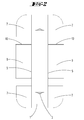
- a middle elongated, a rectangular plan having screw-on portion 1 forms a mounting plate.
- the distance between the inner walls of the side parts 2 is in the region of their roots, ie directly in the region of the longitudinal edges 5 about 60 mm.
- the distance between the inner walls of the side parts 2 from each other is slightly smaller, so that the forming between the side parts 2 Receiving space 6 has a slightly trapezoidal cross-section.
- the height of the side parts 2 is about 40 mm.
- the wings 7 extend approximately in a common plane.
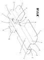
- the cut there section of the side panels 2 forms a parallel to the extension plane of the wings 7 extending extension 9, which forms a fastening device for fixing a roof structure.
- the strip-shaped extension 9 protrude transversely to the extension direction of the receiving space 6 side walls 10 vertically upward, so that the fastening means 9 each form a U-shaped structure.
- the side walls 10 have openings 11 for the passage of nails or screws, with which a lying in the U-structures 10,11 board can be attached to the fastening device.
- the two U-shaped attachment structures 9,10 are spaced apart by the width of the Anschraubabiteses 1.
- the extensions 9, which protrude from the two sides of Anschraubabiteses 1 lie approximately in a common plane.
- the protruding side walls 10 are also in a common plane, however, which extends transversely to the plane of the extensions 9.
- FIGS. 5 to 7 show a fastened to a roof substructure fastening device.
- the roof substructure consists of rafters 24 that run between eaves and ridge.
- a plurality of mutually parallel rafters 24 carry insulating elements 23.
- Parallel to the rafters 24 and at the height of the rafters 24 extend on the insulating elements 23 counter battens 22, which typically have a cross-sectional dimension of 60 mm by 40 mm.
- a fastening device is placed on a counter-lath 22 . Since the clear distance of the two side parts 2 in the region of their free ends 2 'is slightly smaller than the width of the counter-battens, the side parts 2 have to be slightly bent away from each other, so that the fastening device as in the FIGS.
- the side parts 2 are clamped on the side walls of the counter-lath.
- the two side parts 2 extend at an acute angle to each other.
- the side parts 2 can also rest on the side walls of a counter-lath in such a way that they run parallel to one another.
- the attachment of the fastening device to the rafter is done with long, at least 8 mm thick fully threaded mounting screws. These are first screwed through the oblique screw passage openings 3 through the counter battens 22 and then through the insulation 23 until their tip area anchors in the rafters 24. Of the FIG. 5 It can be seen that the fastening screws 5 run along the legs of a trapezoid. They engage inclined in the opposite direction, obliquely into the rafters 24.
- the fastening device 9 serves to receive a part of a roof structure.
- the fastening device 9 carries a board 25, which is supported on a side wall 10. It can be arranged boards with different width between the two side walls 10.
- the wings 7 are on top of the insulation 23. As a result, pressure forces are introduced into the insulation 23 with reduced surface pressure. Since the wings 7 extend on both sides of the counter-batten 22, they are also able to initiate any applied to the fastening device relative to the direction of extension of the counter-batten 22 torques in the insulation 23. It is thus largely avoided torsion of the counter-batten 22.
- FIGS. 11 to 14 illustrated second embodiment corresponds in essential parts of the first embodiment.
- the cutout 8 is here formed somewhat shorter, so that the wings 7 have a slightly greater length.
- the notches from the cutout 8 are here bent perpendicularly upwards and thus to a certain extent form extensions of the side parts 2.
- These fastening devices 9 protrude from side walls 10, which lie in a common plane.
- the side walls 10 form supporting walls for supporting, for example, a board 25.
- Die FIGS. 12 to 14 show that the second embodiment is mounted on a counter-batten in a manner similar to the first embodiment. It is therefore referred to the above statements.
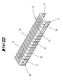
- FIGS. 15 to 21 illustrated embodiment is made of metal.
- This is a cast component.
- the cast component forms a Anschraubabrough 1, which forms the shape of an elongated rectangle. From The longitudinal edges 5 protrude transversely to the plane of extension of the Anschraubabiteses 1 over the entire length of the Anschraubabitess each side parts 2 from.
- the two free ends 2 'of the side parts 2 are spaced less than the width of the counter-battens, so that the fastening device can be placed in a clamping fit on the counter-battens.
- the wings extend here over the entire length of the fastening device and are based in the mounted state on the top of a rafter insulation.
- a first attachment opening 3 is formed by an oblique bore, which gives a direction of inclination with respect to the extension plane of the attachment section 1 to a fastening screw inserted through the screw passage opening 3.
- FIGS. 19 to 21 demonstrate. These figures moreover show that the screw inserted through the screw passage opening 3 'is screwed transversely to its extension direction in the rafters 24. while a second fastening screw 4, which is inserted through the screw passage opening 3, has been screwed in at a 45-degree angle in the rafters 24.
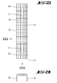
- FIGS. 22 to 25 show an adapter piece. It is a U-shaped plastic body having a U-web 16 and U-leg 17. Of the outer walls of the U-web 16 and the outer walls of the U-legs 17 protrude crosswise extending webs 18,19. These are spacer bars. In the U-web 16 are also two longitudinal slots 21st
- FIG. 26 shows the use of the adapter 15. It is inserted into the receiving space 6 of one of the fastening devices described above and in particular into the receiving space 6 of the third embodiment.
- the latching projections 20 engage in recesses 14 of the side parts 2.
- the adapter is then positively locked in the receiving space 6.
- the ribs 18,19 are supported on the inner walls of the side parts 2 and the underside of the screw-1.
- a device which is characterized by a arranged between longitudinal edges 5 of the Anschraubabitess 1 side parts 2 receiving space 6 for receiving a counter-batten 22;
- a device which is characterized in that the lateral parts 2 projecting transversely from the screw-on portion 1 form pressure zones directed toward one another, for contact with the side walls of the counter-blade 22;
- a device characterized in that the receiving space 6 has a U-shaped cross-section, wherein the U-legs in the region of their free ends 2 'are spaced from each other less than in the region of their adjoining the Anschraubabites 1 ends;
- a device which is characterized in that at least one of the ffersteckstecgro Maschinenen 3 forces the screwing of a fastening screw 4 in an acute-angled alignment in a arranged below the counter batten rafters 24;
- a device which is characterized in that two erstecksteckö Maschinenen 3 are provided for screwing in the extension direction of the counter-plate 22 obliquely oriented away from each other screws 4;
- a device which is characterized in that protrude from the free ends 2 'of the side parts 2 in the direction away from the receiving space 6 wings 7, wherein the wings 7 extend in particular in a common plane to rest on a provided between counter-battens 22 and rafters 24 Aufsparrendämmung 23 are provided;
- a device which is characterized in that in each case two side parts 2 are respectively provided at the ends of the Anschraubabitess;
- a device which is characterized by an insertable into the receiving space 6 adapter 15 to reduce the clear width of the receiving space. 6
Landscapes
- Engineering & Computer Science (AREA)
- Architecture (AREA)
- Civil Engineering (AREA)
- Structural Engineering (AREA)
- Joining Of Building Structures In Genera (AREA)
- Roof Covering Using Slabs Or Stiff Sheets (AREA)
Priority Applications (1)
| Application Number | Priority Date | Filing Date | Title |
|---|---|---|---|
| PL15172926T PL2963202T3 (pl) | 2014-07-03 | 2015-06-19 | Stosowanie przyrządu mocującego dla mocowania elementów konstrukcji stromego dachu |
Applications Claiming Priority (1)
| Application Number | Priority Date | Filing Date | Title |
|---|---|---|---|
| DE102014109329.1A DE102014109329A1 (de) | 2014-07-03 | 2014-07-03 | Befestigungsvorrichtung zur Befestigung von Dachaufbauten an einem Steildach |
Publications (2)
| Publication Number | Publication Date |
|---|---|
| EP2963202A1 true EP2963202A1 (fr) | 2016-01-06 |
| EP2963202B1 EP2963202B1 (fr) | 2018-03-21 |
Family
ID=53785398
Family Applications (1)
| Application Number | Title | Priority Date | Filing Date |
|---|---|---|---|
| EP15172926.6A Active EP2963202B1 (fr) | 2014-07-03 | 2015-06-19 | Utlisation d'un dispositif de fixation de structures de toit sur un toit en pente |
Country Status (5)
| Country | Link |
|---|---|
| EP (1) | EP2963202B1 (fr) |
| DE (1) | DE102014109329A1 (fr) |
| DK (1) | DK2963202T3 (fr) |
| HU (1) | HUE037710T2 (fr) |
| PL (1) | PL2963202T3 (fr) |
Families Citing this family (1)
| Publication number | Priority date | Publication date | Assignee | Title |
|---|---|---|---|---|
| DE102016125201A1 (de) * | 2016-12-21 | 2018-06-21 | Ludwig Hettich Holding Gmbh & Co. Kg | System zum Fügen oder Armieren von Bauteilen |
Citations (11)
| Publication number | Priority date | Publication date | Assignee | Title |
|---|---|---|---|---|
| FR2105002A1 (fr) * | 1970-09-15 | 1972-04-28 | Lamotte Georges | |
| EP0119077A2 (fr) * | 1983-03-10 | 1984-09-19 | The Dow Chemical Company | Fixation d'isolation de toit |
| GB2151274A (en) * | 1983-12-12 | 1985-07-17 | Cheater Maurice J | Support members for cladding |
| DE202005002473U1 (de) * | 2004-02-21 | 2005-04-21 | Fritz Homann Gmbh & Co. Kg | Wärmedämmsystem für ein Dach |
| DE202005020804U1 (de) * | 2005-01-11 | 2006-08-17 | Opitz Holzbau Gmbh & Co. Kg | Stoßverbindung |
| DE202007015887U1 (de) | 2007-11-14 | 2008-02-21 | Leichtmetallbau Schletter Gmbh | Befestigung für einen Dachhaken |
| DE102009022161A1 (de) | 2009-05-20 | 2010-12-09 | Rensburg, Markus, Dipl.-Wirtsch.-Ing. | Befestigungselement für Dachaufbauten, insbesondere Solaranlagen, Dachaufbauten mit einem derartigen Befestiger und Verfahren zum Verbinden eines Dachaufbaus mit einem Dach |
| CH702527A2 (de) * | 2010-01-08 | 2011-07-15 | Brawand Zimmerei Ag | Dach-Unterkonstruktion. |
| DE102010037831A1 (de) | 2010-09-28 | 2012-03-29 | Sfs Intec Holding Ag | Befestigungsvorrichtung an einem Gebäude |
| US20120291382A1 (en) * | 2011-05-18 | 2012-11-22 | Cool Roof Innovations Inc. | Cool roof batten assembly |
| DE102012016634A1 (de) * | 2012-08-22 | 2014-02-27 | Gustav Bohrenkämper | Zuganker |
Family Cites Families (1)
| Publication number | Priority date | Publication date | Assignee | Title |
|---|---|---|---|---|
| US4432182A (en) * | 1981-09-17 | 1984-02-21 | Armstrong World Industries, Inc. | Ceiling tile suspension system |
-
2014
- 2014-07-03 DE DE102014109329.1A patent/DE102014109329A1/de not_active Withdrawn
-
2015
- 2015-06-19 PL PL15172926T patent/PL2963202T3/pl unknown
- 2015-06-19 HU HUE15172926A patent/HUE037710T2/hu unknown
- 2015-06-19 DK DK15172926.6T patent/DK2963202T3/en active
- 2015-06-19 EP EP15172926.6A patent/EP2963202B1/fr active Active
Patent Citations (11)
| Publication number | Priority date | Publication date | Assignee | Title |
|---|---|---|---|---|
| FR2105002A1 (fr) * | 1970-09-15 | 1972-04-28 | Lamotte Georges | |
| EP0119077A2 (fr) * | 1983-03-10 | 1984-09-19 | The Dow Chemical Company | Fixation d'isolation de toit |
| GB2151274A (en) * | 1983-12-12 | 1985-07-17 | Cheater Maurice J | Support members for cladding |
| DE202005002473U1 (de) * | 2004-02-21 | 2005-04-21 | Fritz Homann Gmbh & Co. Kg | Wärmedämmsystem für ein Dach |
| DE202005020804U1 (de) * | 2005-01-11 | 2006-08-17 | Opitz Holzbau Gmbh & Co. Kg | Stoßverbindung |
| DE202007015887U1 (de) | 2007-11-14 | 2008-02-21 | Leichtmetallbau Schletter Gmbh | Befestigung für einen Dachhaken |
| DE102009022161A1 (de) | 2009-05-20 | 2010-12-09 | Rensburg, Markus, Dipl.-Wirtsch.-Ing. | Befestigungselement für Dachaufbauten, insbesondere Solaranlagen, Dachaufbauten mit einem derartigen Befestiger und Verfahren zum Verbinden eines Dachaufbaus mit einem Dach |
| CH702527A2 (de) * | 2010-01-08 | 2011-07-15 | Brawand Zimmerei Ag | Dach-Unterkonstruktion. |
| DE102010037831A1 (de) | 2010-09-28 | 2012-03-29 | Sfs Intec Holding Ag | Befestigungsvorrichtung an einem Gebäude |
| US20120291382A1 (en) * | 2011-05-18 | 2012-11-22 | Cool Roof Innovations Inc. | Cool roof batten assembly |
| DE102012016634A1 (de) * | 2012-08-22 | 2014-02-27 | Gustav Bohrenkämper | Zuganker |
Also Published As
| Publication number | Publication date |
|---|---|
| DE102014109329A1 (de) | 2016-01-07 |
| PL2963202T3 (pl) | 2018-07-31 |
| EP2963202B1 (fr) | 2018-03-21 |
| HUE037710T2 (hu) | 2018-09-28 |
| DK2963202T3 (en) | 2018-06-18 |
Similar Documents
| Publication | Publication Date | Title |
|---|---|---|
| EP2828588B1 (fr) | Système de fixation pour module solaire | |
| EP2270403B1 (fr) | Collecteur solaire avec rail de support | |
| DE20015534U1 (de) | Klemmlasche | |
| EP2971354A1 (fr) | Fixation de rail comportant une fixation par attaches entre la plaque de guidage et la plaque de support | |
| EP2816172A2 (fr) | Système de montage pour un revêtement de sol | |
| EP2589725B1 (fr) | Élément de liaison et système de profil d'aération pour façades de bâtiments ventilées à l'arrière | |
| EP0430224B1 (fr) | Dispositif de fixation | |
| EP2963202B1 (fr) | Utlisation d'un dispositif de fixation de structures de toit sur un toit en pente | |
| EP2604770A2 (fr) | Agencement de fixation de plaques | |
| EP2508816B1 (fr) | Crochet de toit | |
| EP2322874A1 (fr) | Crochet de toit | |
| EP1647649A2 (fr) | Système de fixation de façades | |
| EP3176344B1 (fr) | Élément de faite ou d'arête de toit | |
| EP2944740B1 (fr) | Système et corps de liaison | |
| EP0510563B1 (fr) | Rail d'écartement et de fixation profilé | |
| EP2927390B1 (fr) | Dispositif de maintien de façades | |
| DE29501224U1 (de) | Unterkonstruktion für mit Dachplatten eingedeckte Steildächer | |
| DE102004022279B4 (de) | Vorrichtung zur Befestigung von Dämmstoffelementen an ebenen Flächen | |
| DE10147840C2 (de) | Wandverkleidung | |
| DE202019103487U1 (de) | Spreizbarer Eckwinkel | |
| AT507842A1 (de) | Verbindungselement zur fluchtenden verbindung benachbarter gittermatten und damit gebauter zaun | |
| DE102023117924A1 (de) | Befestiger zu einer Befestigung einer Montageschiene für Photovoltaikmodule auf einem Ziegeldach und Ziegeldach mit dem Befestiger | |
| EP2574202B1 (fr) | Élément de fixation | |
| DE102022130512A1 (de) | Befestigungsmittel zum Befestigen von Gegenständen an Profilen, insbesondere von Gittermatten an Zaunpfählen oder von Gegenständen an Montageprofilen | |
| EP1319769B1 (fr) | Panneau isolant pour toiture |
Legal Events
| Date | Code | Title | Description |
|---|---|---|---|
| PUAI | Public reference made under article 153(3) epc to a published international application that has entered the european phase |
Free format text: ORIGINAL CODE: 0009012 |
|
| AK | Designated contracting states |
Kind code of ref document: A1 Designated state(s): AL AT BE BG CH CY CZ DE DK EE ES FI FR GB GR HR HU IE IS IT LI LT LU LV MC MK MT NL NO PL PT RO RS SE SI SK SM TR |
|
| AX | Request for extension of the european patent |
Extension state: BA ME |
|
| 17P | Request for examination filed |
Effective date: 20160210 |
|
| RBV | Designated contracting states (corrected) |
Designated state(s): AL AT BE BG CH CY CZ DE DK EE ES FI FR GB GR HR HU IE IS IT LI LT LU LV MC MK MT NL NO PL PT RO RS SE SI SK SM TR |
|
| 17Q | First examination report despatched |
Effective date: 20161220 |
|
| GRAP | Despatch of communication of intention to grant a patent |
Free format text: ORIGINAL CODE: EPIDOSNIGR1 |
|
| INTG | Intention to grant announced |
Effective date: 20170621 |
|
| GRAS | Grant fee paid |
Free format text: ORIGINAL CODE: EPIDOSNIGR3 |
|
| GRAJ | Information related to disapproval of communication of intention to grant by the applicant or resumption of examination proceedings by the epo deleted |
Free format text: ORIGINAL CODE: EPIDOSDIGR1 |
|
| GRAL | Information related to payment of fee for publishing/printing deleted |
Free format text: ORIGINAL CODE: EPIDOSDIGR3 |
|
| GRAP | Despatch of communication of intention to grant a patent |
Free format text: ORIGINAL CODE: EPIDOSNIGR1 |
|
| INTG | Intention to grant announced |
Effective date: 20171110 |
|
| GRAA | (expected) grant |
Free format text: ORIGINAL CODE: 0009210 |
|
| AK | Designated contracting states |
Kind code of ref document: B1 Designated state(s): AL AT BE BG CH CY CZ DE DK EE ES FI FR GB GR HR HU IE IS IT LI LT LU LV MC MK MT NL NO PL PT RO RS SE SI SK SM TR |
|
| REG | Reference to a national code |
Ref country code: GB Ref legal event code: FG4D Free format text: NOT ENGLISH |
|
| RIN1 | Information on inventor provided before grant (corrected) |
Inventor name: MUELLER, CATRIN Inventor name: LABBAD, BASILIUS |
|
| REG | Reference to a national code |
Ref country code: CH Ref legal event code: EP |
|
| REG | Reference to a national code |
Ref country code: AT Ref legal event code: REF Ref document number: 981262 Country of ref document: AT Kind code of ref document: T Effective date: 20180415 |
|
| REG | Reference to a national code |
Ref country code: IE Ref legal event code: FG4D Free format text: LANGUAGE OF EP DOCUMENT: GERMAN |
|
| REG | Reference to a national code |
Ref country code: DE Ref legal event code: R096 Ref document number: 502015003499 Country of ref document: DE |
|
| REG | Reference to a national code |
Ref country code: SE Ref legal event code: TRGR |
|
| REG | Reference to a national code |
Ref country code: NL Ref legal event code: FP |
|
| REG | Reference to a national code |
Ref country code: EE Ref legal event code: FG4A Ref document number: E015386 Country of ref document: EE Effective date: 20180410 Ref country code: CH Ref legal event code: NV Representative=s name: FELBER UND PARTNER AG, CH |
|
| REG | Reference to a national code |
Ref country code: DK Ref legal event code: T3 Effective date: 20180613 |
|
| PG25 | Lapsed in a contracting state [announced via postgrant information from national office to epo] |
Ref country code: LT Free format text: LAPSE BECAUSE OF FAILURE TO SUBMIT A TRANSLATION OF THE DESCRIPTION OR TO PAY THE FEE WITHIN THE PRESCRIBED TIME-LIMIT Effective date: 20180321 Ref country code: CY Free format text: LAPSE BECAUSE OF FAILURE TO SUBMIT A TRANSLATION OF THE DESCRIPTION OR TO PAY THE FEE WITHIN THE PRESCRIBED TIME-LIMIT Effective date: 20180321 Ref country code: HR Free format text: LAPSE BECAUSE OF FAILURE TO SUBMIT A TRANSLATION OF THE DESCRIPTION OR TO PAY THE FEE WITHIN THE PRESCRIBED TIME-LIMIT Effective date: 20180321 |
|
| REG | Reference to a national code |
Ref country code: LT Ref legal event code: MG4D |
|
| REG | Reference to a national code |
Ref country code: NO Ref legal event code: T2 Effective date: 20180321 |
|
| PG25 | Lapsed in a contracting state [announced via postgrant information from national office to epo] |
Ref country code: GR Free format text: LAPSE BECAUSE OF FAILURE TO SUBMIT A TRANSLATION OF THE DESCRIPTION OR TO PAY THE FEE WITHIN THE PRESCRIBED TIME-LIMIT Effective date: 20180622 Ref country code: BG Free format text: LAPSE BECAUSE OF FAILURE TO SUBMIT A TRANSLATION OF THE DESCRIPTION OR TO PAY THE FEE WITHIN THE PRESCRIBED TIME-LIMIT Effective date: 20180621 Ref country code: LV Free format text: LAPSE BECAUSE OF FAILURE TO SUBMIT A TRANSLATION OF THE DESCRIPTION OR TO PAY THE FEE WITHIN THE PRESCRIBED TIME-LIMIT Effective date: 20180321 Ref country code: RS Free format text: LAPSE BECAUSE OF FAILURE TO SUBMIT A TRANSLATION OF THE DESCRIPTION OR TO PAY THE FEE WITHIN THE PRESCRIBED TIME-LIMIT Effective date: 20180321 |
|
| PG25 | Lapsed in a contracting state [announced via postgrant information from national office to epo] |
Ref country code: MT Free format text: LAPSE BECAUSE OF FAILURE TO SUBMIT A TRANSLATION OF THE DESCRIPTION OR TO PAY THE FEE WITHIN THE PRESCRIBED TIME-LIMIT Effective date: 20180321 |
|
| REG | Reference to a national code |
Ref country code: HU Ref legal event code: AG4A Ref document number: E037710 Country of ref document: HU |
|
| PG25 | Lapsed in a contracting state [announced via postgrant information from national office to epo] |
Ref country code: ES Free format text: LAPSE BECAUSE OF FAILURE TO SUBMIT A TRANSLATION OF THE DESCRIPTION OR TO PAY THE FEE WITHIN THE PRESCRIBED TIME-LIMIT Effective date: 20180321 Ref country code: AL Free format text: LAPSE BECAUSE OF FAILURE TO SUBMIT A TRANSLATION OF THE DESCRIPTION OR TO PAY THE FEE WITHIN THE PRESCRIBED TIME-LIMIT Effective date: 20180321 Ref country code: RO Free format text: LAPSE BECAUSE OF FAILURE TO SUBMIT A TRANSLATION OF THE DESCRIPTION OR TO PAY THE FEE WITHIN THE PRESCRIBED TIME-LIMIT Effective date: 20180321 Ref country code: IT Free format text: LAPSE BECAUSE OF FAILURE TO SUBMIT A TRANSLATION OF THE DESCRIPTION OR TO PAY THE FEE WITHIN THE PRESCRIBED TIME-LIMIT Effective date: 20180321 |
|
| PG25 | Lapsed in a contracting state [announced via postgrant information from national office to epo] |
Ref country code: SM Free format text: LAPSE BECAUSE OF FAILURE TO SUBMIT A TRANSLATION OF THE DESCRIPTION OR TO PAY THE FEE WITHIN THE PRESCRIBED TIME-LIMIT Effective date: 20180321 Ref country code: SK Free format text: LAPSE BECAUSE OF FAILURE TO SUBMIT A TRANSLATION OF THE DESCRIPTION OR TO PAY THE FEE WITHIN THE PRESCRIBED TIME-LIMIT Effective date: 20180321 |
|
| PG25 | Lapsed in a contracting state [announced via postgrant information from national office to epo] |
Ref country code: PT Free format text: LAPSE BECAUSE OF FAILURE TO SUBMIT A TRANSLATION OF THE DESCRIPTION OR TO PAY THE FEE WITHIN THE PRESCRIBED TIME-LIMIT Effective date: 20180723 |
|
| REG | Reference to a national code |
Ref country code: DE Ref legal event code: R097 Ref document number: 502015003499 Country of ref document: DE |
|
| PLBE | No opposition filed within time limit |
Free format text: ORIGINAL CODE: 0009261 |
|
| STAA | Information on the status of an ep patent application or granted ep patent |
Free format text: STATUS: NO OPPOSITION FILED WITHIN TIME LIMIT |
|
| 26N | No opposition filed |
Effective date: 20190102 |
|
| REG | Reference to a national code |
Ref country code: IE Ref legal event code: MM4A |
|
| PG25 | Lapsed in a contracting state [announced via postgrant information from national office to epo] |
Ref country code: LU Free format text: LAPSE BECAUSE OF NON-PAYMENT OF DUE FEES Effective date: 20180619 Ref country code: MC Free format text: LAPSE BECAUSE OF FAILURE TO SUBMIT A TRANSLATION OF THE DESCRIPTION OR TO PAY THE FEE WITHIN THE PRESCRIBED TIME-LIMIT Effective date: 20180321 |
|
| PG25 | Lapsed in a contracting state [announced via postgrant information from national office to epo] |
Ref country code: FR Free format text: LAPSE BECAUSE OF NON-PAYMENT OF DUE FEES Effective date: 20180630 Ref country code: IE Free format text: LAPSE BECAUSE OF NON-PAYMENT OF DUE FEES Effective date: 20180619 |
|
| PG25 | Lapsed in a contracting state [announced via postgrant information from national office to epo] |
Ref country code: SI Free format text: LAPSE BECAUSE OF FAILURE TO SUBMIT A TRANSLATION OF THE DESCRIPTION OR TO PAY THE FEE WITHIN THE PRESCRIBED TIME-LIMIT Effective date: 20180321 |
|
| GBPC | Gb: european patent ceased through non-payment of renewal fee |
Effective date: 20190619 |
|
| PG25 | Lapsed in a contracting state [announced via postgrant information from national office to epo] |
Ref country code: TR Free format text: LAPSE BECAUSE OF FAILURE TO SUBMIT A TRANSLATION OF THE DESCRIPTION OR TO PAY THE FEE WITHIN THE PRESCRIBED TIME-LIMIT Effective date: 20180321 |
|
| PG25 | Lapsed in a contracting state [announced via postgrant information from national office to epo] |
Ref country code: GB Free format text: LAPSE BECAUSE OF NON-PAYMENT OF DUE FEES Effective date: 20190619 |
|
| PG25 | Lapsed in a contracting state [announced via postgrant information from national office to epo] |
Ref country code: MK Free format text: LAPSE BECAUSE OF NON-PAYMENT OF DUE FEES Effective date: 20180321 |
|
| PG25 | Lapsed in a contracting state [announced via postgrant information from national office to epo] |
Ref country code: IS Free format text: LAPSE BECAUSE OF FAILURE TO SUBMIT A TRANSLATION OF THE DESCRIPTION OR TO PAY THE FEE WITHIN THE PRESCRIBED TIME-LIMIT Effective date: 20180721 |
|
| P01 | Opt-out of the competence of the unified patent court (upc) registered |
Effective date: 20230512 |
|
| PGFP | Annual fee paid to national office [announced via postgrant information from national office to epo] |
Ref country code: FI Payment date: 20250617 Year of fee payment: 11 |
|
| PGFP | Annual fee paid to national office [announced via postgrant information from national office to epo] |
Ref country code: DE Payment date: 20250618 Year of fee payment: 11 Ref country code: PL Payment date: 20250609 Year of fee payment: 11 |
|
| PGFP | Annual fee paid to national office [announced via postgrant information from national office to epo] |
Ref country code: DK Payment date: 20250618 Year of fee payment: 11 |
|
| PGFP | Annual fee paid to national office [announced via postgrant information from national office to epo] |
Ref country code: NO Payment date: 20250617 Year of fee payment: 11 |
|
| PGFP | Annual fee paid to national office [announced via postgrant information from national office to epo] |
Ref country code: NL Payment date: 20250618 Year of fee payment: 11 Ref country code: BE Payment date: 20250617 Year of fee payment: 11 |
|
| PGFP | Annual fee paid to national office [announced via postgrant information from national office to epo] |
Ref country code: EE Payment date: 20250618 Year of fee payment: 11 |
|
| PGFP | Annual fee paid to national office [announced via postgrant information from national office to epo] |
Ref country code: AT Payment date: 20250616 Year of fee payment: 11 |
|
| PGFP | Annual fee paid to national office [announced via postgrant information from national office to epo] |
Ref country code: CZ Payment date: 20250610 Year of fee payment: 11 |
|
| PGFP | Annual fee paid to national office [announced via postgrant information from national office to epo] |
Ref country code: SE Payment date: 20250618 Year of fee payment: 11 |
|
| PGFP | Annual fee paid to national office [announced via postgrant information from national office to epo] |
Ref country code: HU Payment date: 20250616 Year of fee payment: 11 |
|
| PGFP | Annual fee paid to national office [announced via postgrant information from national office to epo] |
Ref country code: CH Payment date: 20250701 Year of fee payment: 11 |