EP2574202B1 - Élément de fixation - Google Patents
Élément de fixation Download PDFInfo
- Publication number
- EP2574202B1 EP2574202B1 EP12724548.8A EP12724548A EP2574202B1 EP 2574202 B1 EP2574202 B1 EP 2574202B1 EP 12724548 A EP12724548 A EP 12724548A EP 2574202 B1 EP2574202 B1 EP 2574202B1
- Authority
- EP
- European Patent Office
- Prior art keywords
- base
- bridge part
- securing element
- limbs
- flange
- Prior art date
- Legal status (The legal status is an assumption and is not a legal conclusion. Google has not performed a legal analysis and makes no representation as to the accuracy of the status listed.)
- Active
Links
Images




Classifications
-
- F—MECHANICAL ENGINEERING; LIGHTING; HEATING; WEAPONS; BLASTING
- F16—ENGINEERING ELEMENTS AND UNITS; GENERAL MEASURES FOR PRODUCING AND MAINTAINING EFFECTIVE FUNCTIONING OF MACHINES OR INSTALLATIONS; THERMAL INSULATION IN GENERAL
- F16B—DEVICES FOR FASTENING OR SECURING CONSTRUCTIONAL ELEMENTS OR MACHINE PARTS TOGETHER, e.g. NAILS, BOLTS, CIRCLIPS, CLAMPS, CLIPS OR WEDGES; JOINTS OR JOINTING
- F16B37/00—Nuts or like thread-engaging members
- F16B37/04—Devices for fastening nuts to surfaces, e.g. sheets, plates
- F16B37/044—Nut cages
-
- F—MECHANICAL ENGINEERING; LIGHTING; HEATING; WEAPONS; BLASTING
- F16—ENGINEERING ELEMENTS AND UNITS; GENERAL MEASURES FOR PRODUCING AND MAINTAINING EFFECTIVE FUNCTIONING OF MACHINES OR INSTALLATIONS; THERMAL INSULATION IN GENERAL
- F16B—DEVICES FOR FASTENING OR SECURING CONSTRUCTIONAL ELEMENTS OR MACHINE PARTS TOGETHER, e.g. NAILS, BOLTS, CIRCLIPS, CLAMPS, CLIPS OR WEDGES; JOINTS OR JOINTING
- F16B5/00—Joining sheets or plates, e.g. panels, to one another or to strips or bars parallel to them
- F16B5/06—Joining sheets or plates, e.g. panels, to one another or to strips or bars parallel to them by means of clamps or clips
- F16B5/0607—Joining sheets or plates, e.g. panels, to one another or to strips or bars parallel to them by means of clamps or clips joining sheets or plates to each other
- F16B5/0621—Joining sheets or plates, e.g. panels, to one another or to strips or bars parallel to them by means of clamps or clips joining sheets or plates to each other in parallel relationship
- F16B5/0635—Joining sheets or plates, e.g. panels, to one another or to strips or bars parallel to them by means of clamps or clips joining sheets or plates to each other in parallel relationship fastened over the edges of the sheets or plates
-
- F—MECHANICAL ENGINEERING; LIGHTING; HEATING; WEAPONS; BLASTING
- F16—ENGINEERING ELEMENTS AND UNITS; GENERAL MEASURES FOR PRODUCING AND MAINTAINING EFFECTIVE FUNCTIONING OF MACHINES OR INSTALLATIONS; THERMAL INSULATION IN GENERAL
- F16B—DEVICES FOR FASTENING OR SECURING CONSTRUCTIONAL ELEMENTS OR MACHINE PARTS TOGETHER, e.g. NAILS, BOLTS, CIRCLIPS, CLAMPS, CLIPS OR WEDGES; JOINTS OR JOINTING
- F16B5/00—Joining sheets or plates, e.g. panels, to one another or to strips or bars parallel to them
- F16B5/12—Fastening strips or bars to sheets or plates, e.g. rubber strips, decorative strips for motor vehicles, by means of clips
- F16B5/123—Auxiliary fasteners specially designed for this purpose
- F16B5/125—Auxiliary fasteners specially designed for this purpose one of the auxiliary fasteners is comprising wire or sheet material or is made thereof
Definitions
- the invention relates to a fastening element for fastening sheet metal or other loads on flanges or other projections of support profiles by means of an engageable on or in the sheet to be fastened or the load to be fastened or arranged on this / this fastener.
- a preferred field of application of the invention is the attachment of tear sheets to steel girders of steel construction substructures for the construction of podiums and platforms as floor constructions.
- the mounting bracket for attachment of support profiles or clamping profiles to support profiles with running in the longitudinal directionjansnut known.
- the mounting bracket consists of a base body with a bridge portion and at two opposite ends of the bridge portion each having a support portion, said bridge portion having at least two spaced apart openings for insertion of a fastener, wherein at least one of the two openings in the bridge portion is formed as a slot extending to extends to a side edge of the bridge portion and extending at least two of the slots of mutually opposite side edges of the bridge portion.
- the mounting bracket can be mounted in at least two different positions on the support section, wherein for fastening the mounting bracket on the support profile a screw hook engages through one of the openings in the bridge section in the functional groove of the support profile and braces the fastener with a screwed onto the threaded shank of the screw hook knurled nut against the support profile becomes.
- the at the ends of the bridge section arranged support sections serve for a pressing of a to be connected to the support profile further support profile or a clamping profile against the support profile and on the other to support the mounting bracket on the support section.
- the above-described mounting bracket has a very limited field of application and is not suitable for fastening sheets to steel construction substructures.
- the mounting clip is placed on the threaded shank of the screw so that the bend of its arcuate central portion is spaced from the floor panel and one of the arcuate position fuses on the underside of the floor panel and the opposite arcuate position assurance rests against the underside of the horizontal flange of the beam.
- a nut is screwed and clamped the mounting clip against the underside of the floor panel and the underside of the horizontal flange.
- the floor panel is braced against the horizontal flange and held.
- the disadvantage of this solution is that due to the elastic deformation of the fastening clip, the achievable contact pressure is limited and the clip can be used only to a limited extent for different thicknesses flanges. In addition, the clip is not secured against slipping relative to the horizontal flange.
- fastener for fixing wood or wood fiber boards to a metal profile with at least one flange to which the wood or wood fiber board is brought to bear, is from the US 2,369,595 A known.
- the fastener has a U-shaped cross-section, with a bottom and adjacent thereto adjacent legs. In the bottom of the fastener a specific for the engagement of a threaded screw hole is introduced. At the bottom of the fastener facing away from the end face of one of the two legs are formed two pointed expiring spikes.
- the fastener For fixing a wood fiber plate to a metal profile with a flange against which the wood fiber board, the fastener is arranged such that the remote from the bottom of the fastener end face of the not-pointed leg just rests on the flange of the metal profile, while the teeth of the front page of the other leg to get up on the fiberboard.
- the thread With a cross through the wood fiber plate screw, the thread is brought into engagement with the bore in the bottom of the fastener, the fastener is clamped against the wood fiber plate, wherein the prongs penetrate into the wood fiber board and the fastener against slipping establish. At the same time, the wood fiber board is pressed against the flange.
- fastener is characterized by a simple structure, but it has no great stability, so that the realizable forces for pressing the wood fiber board are limited to the flange of the metal profile.
- To attach a wood fiber board to a metal profile therefore a larger number of fasteners are provided according to the description of the invention.
- a further disadvantage is that the fastener is only suitable for attachment of wood or wood fiber boards to a metal profile.
- the retaining claw for attaching a scraper on a snowplow known.
- the retaining claw has two arranged on opposite sides differently high trained beads and a through hole.
- To attach the scraper it is pushed under the less highly trained bead and pressed the retaining claws by means of a cross-through the through hole clamping screw against the scraper.
- the higher trained bead rests against a mounting plate and thus supports the retaining claws and at the same time counteracts tilting of the retaining claw.
- the holding claw is solid.
- the disadvantage is that the retaining claws is very specially designed for attachment of Räumangn with predetermined dimensions in a narrow limited range and the clearing strip to be fixed must be positioned very accurately in order to achieve a sufficiently good attachment.
- a fastener for fixing sheet metal profile grids to a steel substructure which is formed by two to the thickness of the upper flange of the steel substructure, on which rests the sheet metal profile grille to be fastened, adapted clip brackets which engage around the upper flange connected by means of a connecting element.
- the application of this fastener is thus bound to the dimensions of the upper flange of a predetermined steel substructure.
- page 65 is an eccentrically stepped clamp for Fixing of floor panels on the flange of a support of a steel substructure known.
- the clamp is made of malleable cast iron and has circumferential steps around a sleeve provided with a central threaded hole, similar to a spiral staircase.
- a screw engages through a hole made directly adjacent to the flange of the carrier in the bottom plate.
- the screw is screwed into the central threaded hole of the sleeve.
- the clamp is positioned by turning it around the central threaded hole so that one step of the clamp lies flush against the flange.
- a disadvantage is the one that must be placed for mounting in the bottom plate holes immediately adjacent to the flange of the carrier to which the bottom plate is to be attached, and that the connection terminal flange is subjected to a load unbalance, resulting in slipping Clamp from the flange can lead to oscillating load.
- the terminal has on two opposite sides on the one hand a clamping surface and on the other hand a cam.
- a clamping surface In front of the clamping surface extends a provided with a toothed terminal lug.
- Central is a through hole for the passage of a clamping screw arranged.
- a screw engages through a hole introduced directly next to the flange into the component.
- the clamp is arranged so that the flange is positioned under the clamping surface.
- the object of the invention is to provide a fastener for attachment of sheets or other loads on flanges or other projections of support profiles, in particular of tear sheets on steel beams of Stahbauunterkonstrutationen, with which the disadvantages of the prior art are avoided.
- the fastener should preferably be suitable for oscillating loads, sufficiently universal, i.
- a sufficient tolerance compensation between the position of the hole to be introduced into the sheet or the load for mounting or arranged on the plate or the load fastening means and the position of the flange or the projection allow in relation to the sheet metal or the load and sufficiently stable, ie for applying a sufficiently large contact pressure between the flange or the projection and the sheet or the load to be formed.
- An inventive fastener has a cross-sectionally U-shaped bridge portion with a rectangular shaped bottom and two molded on the longitudinal sides of the floor at the bottom legs and two opposite to the front sides of the U-shaped bridge member opposite to the direction of the legs different high support elements on both sides protrude beyond the width of the bottom and at the over the width of the bottom protruding areas in the direction of the legs have contact surfaces.
- the legs protrude beyond the length of the floor and, at the areas projecting over the length of the floor, have contact surfaces pointing in the direction of the supporting elements, which are formed corresponding to the contact surfaces located on the supporting elements.
- In the bottom of the bridge part is a hole.
- the ratio of length to width of the rectangular bottom is preferably greater than 1.5, particularly preferably greater than 2.
- At least two knob-like material ejections are expediently formed at the end faces of the supporting elements facing away from the bottom of the bridge part.
- a nut is arranged between the legs of the bridge part with its threaded bore in alignment with the bore in the bottom of the U-shaped bridge part.
- the nut is held against slipping within the U-shaped bridge member as well as against sliding out of the U-shaped bridge portion of two arranged on the legs formable tabs.
- the dimensions of the nut and the opening width of the U-shaped bridge part i. the width between the legs of the bridge part, with each other so that the nut between the legs of the bridge member is held against rotation.
- the nut between the legs of the U-shaped bridge member and by said arranged on the legs deformable tabs in their position is not fixed firmly, but held only with play against twisting, slipping and slipping out of the U-shaped bridge part.
- the fastener is advantageously made from a sheet metal blank by bending, the legs and the support elements are folded relative to the bottom of the U-shaped bridge member in each case by an angle of about 90 °.
- the legs and the support elements point in opposite directions.
- the sheet has a thickness between 2.0 mm to 4.0 mm and has the ratio length of the bottom (3) to the height of the leg (4) has a value between 0.2 to 0.35.
- Such a sized fastener has sufficient dimensional stability for the attachment of a sheet or other load on a flange or on a projection of a supporting profile.
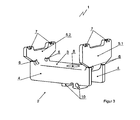
- FIG. 1 shows a fastener 1 with a cross-sectionally U-shaped bridge part 2.
- the U-shaped bridge part 2 has a rectangular shaped bottom 3 with a length to width ratio> 2.5 and two on the longitudinal sides of the bottom 3 at the bottom 3 molded leg 4
- support elements 5.1 and 5.2 are formed, each projecting on both sides over the width of the bottom 3 and to the width of the bottom 3 protruding areas in the direction of the legs have contact surfaces 6, the support elements 5.1 and 5.2 are of different heights. They have a height difference of 2 mm to 15 mm, preferably from 5 mm to 10 mm.
- the legs 4 protrude on both sides over the length of the bottom 3 and have at the over the length of the bottom 3 protruding areas in the direction of the support elements 5.1, 5.2 facing contact surfaces 6, which are formed corresponding to the support surfaces located on the 5.1, 5.2 contact surfaces 6 , At the lateral ends of the end faces of the supporting elements 5.1 and 5.2 two nub-like material ejections 7 are formed in each case.
- the bottom 3 of the bridge part 1 is in the direction of the longitudinal axis of the bridge part 1 to the higher support element 5.1 out offset a bore. 8
- FIG. 2 shows a training of in FIG. 1 illustrated fastener 1, in which below the bore 8 between the legs 4 of the back part 2 in an FIG. 2 not shown nut 9 is arranged.
- the nut 9 is held against slipping in the longitudinal direction of the U-shaped bridge part 2 and against sliding out of the U-shaped bridge part 2 of two arranged on the legs 4 formable tabs 10.
- the outer dimensions of the nut 9 and the opening width of the U-shaped bridge part 2, ie the width between the legs 4 of the bridge part 2, are coordinated so that the nut 9 between the legs 4 of the bridge part 2 is held against rotation, but not firmly clamped is.
- the nut 9 is not fixed by said arranged on the legs 4 formable tabs 10 in their position, but it is held only with play against slipping and slipping out of the U-shaped bridge part 2 in such a way that their threaded hole by Hin- and pushing the nut 9 in alignment with the bore 8 in the bottom 3 of the U-shaped bridge part 2 can be brought.
- FIGS. 2a to 2c show three side views (2a - side view, 2b - front view and 2c - top view) of the above-described fastener 1.
- the deformable tabs 10 are hook-shaped in this embodiment of the fastener 1. Between the legs 4 is a nut 9, which is held by the legs against rotation. The deformable tabs 10 are reshaped so that the nut 9 is held with play against slipping inside and slipping out of the U-shaped bridge part 2.
- the fastener 1 has each at the lateral ends of the end faces of the support elements 5.1 and 5.2 Material Stammwerfitch 7 in the form of a toothing.
- a toothing on the end faces of the supporting elements 5.1 and 5.2 is particularly suitable for supporting soft, deformable materials.
- FIG. 4 shows a corresponding sheet metal blank.
- the legs 4 are each bent at an angle of 90 ° relative to the bottom 3, so that the U-shaped bridge part 2 is formed, in which case the ratio of the length of the bottom 3 to the height of a leg 4 has a value of 0.23.
- the supporting elements 5.1 and 5.2 are also bent by an angle of 90 °.
- the tabs 10 are bent, whereby the nut 9 is held in the opening of the U-shaped bridge part 2 with play.
- the fold of the legs 4 and the support elements 5.1 and 5.2 at an angle of 90 ° is appropriate, but not mandatory. There are also folds with other angles, for example between 70 ° to 100 °, possible.
- FIGS. 5a, 5b and 5c illustrate the attachment of a sheet 11 on the flange 12 of a double-T-carrier 13.
- a bore 14 was placed next to the flange 12 to which the sheet 11 is to be attached.
- a screw 15 is guided.
- the head 16 of the screw 15 rests on the top of the sheet 11.
- the fastener 1 is placed so that engages the thread of the bolt into the nut 9 of the fastener 1.
- the fastening element 1 is aligned so that the higher support element 5.1 to the underside of the sheet 11, while the shorter support element 5.2 is directed to the flange 12.
- the fastening element 1 By tightening the screw 15, the fastening element 1 is moved in the direction of the underside of the sheet metal 11 and flange 12.
- the Materialaufwerfitch 7 at the end faces of the support elements 5.1 and 5.2 come with further tightening the screw 15 to rest against the underside of the sheet 11 and the flange 12. In this case, the sheet 11 is pressed against the flange 12.
- the contact force acting on the supporting elements 5.1, 5.2 causes a deformation of the frontal region of the bottom 3 by the supporting elements 5.1,5,2 are connected to the bottom 3 in such a way that the supporting elements 5.1, 5.2 in the direction of the side over the length the bottom 3 protruding portions of the legs 4 are moved and the corresponding contact surfaces 6 of the legs 4 and the support elements 5.1.
- the fastener 1 can thus absorb significantly higher forces or significantly higher contact forces between the sheet 11 to be fastened and the flange 12 to which the sheet 11 is to be attached, cause, as would allow the bending strength of a 3 mm thick sheet.
- the bridge part 2 of the fastening element 1 can be aligned either parallel or inclined to the plane of the metal sheet 11 .
- the arranged with play in the U-shaped bridge part 2 nut 9 also allows for a relative to the plane of the sheet 11 inclined position of the U-shaped bridge part 2 a secure contact pressure of the sheet metal eleventh against the flange 12.
- FIGS. 6a and 6b illustrate another variant for fastening a metal sheet 11 to the flange 12 of a double-T beam 13 by means of a fastening element 1 according to the invention.
- a metal sheet 11 is to be fastened to the flange 12 next to the flange 12 Threaded sleeve 17 attached.
- the fastener 1 is as to the FIGS. 5a to 5c described arranged and aligned.
- a screw 15 is screwed into the threaded sleeve 17.
- the screw head 16 of the screw 15 presses on a sleeve 18 against the bottom 3 of the fastener 1, whereby the tightening of the screw 15, the plate 11 is mediated by the fastener 1 against the flange 12 is pressed.
- FIGS. 7a and 7b Another variant for fixing a sheet 11 to the flange 12 of a double carrier 13 by means of a fastening element 1 according to the invention is in the FIGS. 7a and 7b shown.
- bolt 19 On the underside of the flange 12 to be fastened sheet 11 adjacent to the flange 12 a with a transversely to its longitudinal axis aligned opening provided bolt 19 is arranged.
- the fastening element is placed on the bolt 19 so that it engages through the hole 7 in the bottom 3 of the bridge part 2. It is aligned as already described so that the support element 5.1 has the greater height to the underside of the sheet 11, while the support element is 5.2 directed to the flange 12 with the smaller height.
- a key 20 is pushed through said breakthrough in the bolt 19 and pushed so far that the Sheet 11 mediates by the fastener 1 against the flange 12 is pressed.
Landscapes
- Engineering & Computer Science (AREA)
- General Engineering & Computer Science (AREA)
- Mechanical Engineering (AREA)
- Connection Of Plates (AREA)
Claims (10)
- Elément de fixation (1) conçu pour fixer des tôles (11), ou d'autres charges, à des ailes (12) ou autres zones protubérantes de profilés de support (13), à l'aide d'un moyen de fixation (15, 17, 19) pouvant s'engager sur ou dans la tôle (11) à fixer, ou la charge à fixer, ou situé sur cette dernière, sachant que ledit élément de fixation (1) comporte une partie d'entretoisement (2) de section transversale en U, munie d'un fond (3) et de deux branches (4) faisant corps avec les côtés de celui-ci, et qu'un perçage (8), dévolu à la pénétration ou à la traversée dudit moyen de fixation (15, 17, 19), est pratiqué dans le fond (3) de ladite partie d'entretoisement (2), ledit fond (3) étant de réalisation rectangulaire, lesdites branches (4) faisant corps avec les côtés longitudinaux dudit fond (3) et un élément d'appui (5.1, 5.2), orienté en sens inverse de la direction desdites branches (4) de la partie d'entretoisement (2), étant respectivement disposé sur les côtés frontaux dudit fond (3), caractérisé par le fait que l'élément d'appui (5.1, 5.2) fait saillie, de part et d'autre, au-delà de la largeur du fond (3) et présente, dans les régions faisant saillie au-delà de la largeur dudit fond (3), des surfaces de contact (6) pointant dans la direction des branches (4) ; par le fait que lesdites branches (4) font saillie au-delà de la longueur dudit fond (3) et présentent, dans les régions faisant saillie au-delà de la longueur dudit fond (3), des surfaces de contact (6) qui pointent dans la direction des éléments d'appui (5.1, 5.2) et sont réalisées pour concorder avec les surfaces de contact (6) situées sur lesdits éléments d'appui (5.1, 5.2) ; et par le fait que la hauteur desdits éléments d'appui (5.1, 5.2) est différente.
- Elément de fixation (1) selon la revendication 1,
caractérisé par le fait
qu'au moins deux profilages saillants (7), du type lobe, sont façonnés avec espacement mutuel sur les côté frontaux des éléments d'appui (5.1, 5.2) qui pointent à l'opposé du fond (3) de la partie d'entretoisement (2). - Elément de fixation (1) selon la revendication 1 ou 2,
caractérisé par le fait
que le rapport, entre la longueur et la largeur du fond rectangulaire (3) de la partie d'entretoisement (2), est supérieur à 1, 5 et, de préférence, supérieur à 2. - Elément de fixation (1) selon les revendications 1 à 3,
caractérisé par le fait
qu'un écrou (9), dont le trou taraudé est aligné avec le perçage (8) pratiqué dans le fond (3) de la partie d'entretoisement (2), est interposé entre les branches (4) de ladite partie d'entretoisement (2) configurée en U. - Elément de fixation (1) selon la revendication 4,
caractérisé par le fait
que l'écrou (9) est retenu à l'encontre d'une rotation par l'intermédiaire des branches (4) de la partie d'entretoisement (2) configurée en U et, par l'intermédiaire de deux pattes déformables (10) situées sur lesdites branches (4), à l'encontre d'un dérapage le long de l'ouverture de ladite partie d'entretoisement (2) configurée en U, ainsi que d'un ripage hors de ladite ouverture. - Elément de fixation (1) selon la revendication 5,
caractérisé par le fait
que l'écrou (9) est retenu avec jeu dans l'ouverture de la partie d'entretoisement (2) configurée en U. - Elément de fixation (1) selon l'une des revendications 1 à 6,
caractérisé par le fait
que la hauteur des éléments d'appui (5.1, 5.2) diffère de 2 mm à 15 mm, de préférence de 5 mm à 10 mm. - Elément de fixation (1) selon l'une des revendications 1 à 7,
caractérisé par le fait
que ledit élément de fixation (1) est produit par pliage à partir d'un flan en tôle prédécoupé. - Elément de fixation (1) selon la revendication 8,
caractérisé par le fait
que les branches (4) de la partie d'entretoisement (2) configurée en U, ainsi que les éléments d'appui (5.1, 5.2), sont coudés d'un angle respectif d'environ 90° par rapport au fond (3), lesdites branches (4) et lesdits éléments d'appui (5.1, 5.2) étant orientés dans des directions opposées. - Elément de fixation (1) selon la revendication 8 ou 9,
caractérisé par le fait
que ledit élément de fixation (1) est fabriqué en une tôle d'une épaisseur comprise entre 2,0 mm et 4,0 mm et le rapport, entre la longueur du fond (3) et la hauteur de la branche (4), présente une valeur comprise entre 0,2 et 0,35.
Applications Claiming Priority (2)
| Application Number | Priority Date | Filing Date | Title |
|---|---|---|---|
| DE102011101312A DE102011101312A1 (de) | 2011-05-12 | 2011-05-12 | Befestigungselement |
| PCT/DE2012/000260 WO2012152239A1 (fr) | 2011-05-12 | 2012-03-13 | Élément de fixation |
Publications (2)
| Publication Number | Publication Date |
|---|---|
| EP2574202A1 EP2574202A1 (fr) | 2013-04-03 |
| EP2574202B1 true EP2574202B1 (fr) | 2014-10-01 |
Family
ID=46196958
Family Applications (1)
| Application Number | Title | Priority Date | Filing Date |
|---|---|---|---|
| EP12724548.8A Active EP2574202B1 (fr) | 2011-05-12 | 2012-03-13 | Élément de fixation |
Country Status (3)
| Country | Link |
|---|---|
| EP (1) | EP2574202B1 (fr) |
| DE (1) | DE102011101312A1 (fr) |
| WO (1) | WO2012152239A1 (fr) |
Family Cites Families (14)
| Publication number | Priority date | Publication date | Assignee | Title |
|---|---|---|---|---|
| BE425172A (fr) * | ||||
| US2130546A (en) | 1938-02-28 | 1938-09-20 | Gustin Bacon Mfg Co | Floor construction |
| US2369595A (en) | 1940-12-31 | 1945-02-13 | Johns Manville | Wall construction |
| US2615226A (en) * | 1948-05-12 | 1952-10-28 | United Carr Fastener Corp | Turn-in stud mounting molding snap fastener |
| GB671306A (en) * | 1949-12-08 | 1952-04-30 | Robert Seymour Cooke | Improved means for attaching a beading or the like to a fixture |
| DE1828166U (de) * | 1961-01-13 | 1961-03-16 | Continental Elektro Ind Ag | Anschlussklemme fuer elektrische geraete, insbesondere fuer sicherungsunterteile von nh-sicherungen. |
| DE2153140A1 (de) * | 1971-10-26 | 1973-05-03 | Maschf Augsburg Nuernberg Ag | Einrichtung zum befestigen eines einspannbauteiles oder zwei einspannbauteile zwischen zwei klemmschienen |
| CH657678A5 (en) * | 1982-03-11 | 1986-09-15 | Weber Ag Fab Elektro | Device for connecting two flat structural parts, and a connecting element for the device |
| DE29512701U1 (de) * | 1995-08-07 | 1995-10-19 | Beilhack Vertriebs GmbH, 83022 Rosenheim | Schneepflug |
| US6683251B1 (en) * | 2001-06-29 | 2004-01-27 | Pass & Seymour, Inc. | Pressure plate for switch or receptacle |
| DE202005017802U1 (de) | 2005-11-15 | 2006-02-02 | Lichtgitter Gmbh | Befestigungselement zur Festlegung von Blechprofilrosten |
| DE102007040422B3 (de) * | 2007-08-25 | 2008-11-13 | Sew-Eurodrive Gmbh & Co. Kg | Anschlusseinheit zum Anschließen eines oder mehrerer Leiter |
| DE102007051058B4 (de) | 2007-10-18 | 2010-02-18 | Octanorm-Vertriebs-GmbH für Bauelemente | Befestigungsklammer und System zum Erstellen von Aufbauten |
| US8875357B2 (en) * | 2008-07-09 | 2014-11-04 | Tinnerman Palnut Engineered Products, Inc. | Clip |
-
2011
- 2011-05-12 DE DE102011101312A patent/DE102011101312A1/de not_active Withdrawn
-
2012
- 2012-03-13 EP EP12724548.8A patent/EP2574202B1/fr active Active
- 2012-03-13 WO PCT/DE2012/000260 patent/WO2012152239A1/fr not_active Ceased
Also Published As
| Publication number | Publication date |
|---|---|
| EP2574202A1 (fr) | 2013-04-03 |
| DE102011101312A1 (de) | 2012-11-15 |
| WO2012152239A1 (fr) | 2012-11-15 |
Similar Documents
| Publication | Publication Date | Title |
|---|---|---|
| EP2270403B1 (fr) | Collecteur solaire avec rail de support | |
| EP2182226A1 (fr) | Dispositif de fixation | |
| EP1965680A1 (fr) | Element de fixation rapide | |
| EP2944737B1 (fr) | Dispositif de serrage destiné à relier des éléments profilés | |
| EP2816172B1 (fr) | Système de montage pour un revêtement de sol | |
| EP2253902B1 (fr) | Ensemble de composants pour le montage de modules solaires sur un toit | |
| EP1767793A2 (fr) | Dispositif de fixation pour la fixation des panneaux solaires à un rail d'assemblage | |
| EP2372269A2 (fr) | Dispositif de liaison et agencement de profilé | |
| DE202010012937U1 (de) | Befestigungssystem | |
| DE4340410C2 (de) | Oberflächenentwässerungseinrichtung | |
| EP0647747B1 (fr) | Structure porteuse pour la couverture et/ou le recouvrement extérieur des bâtiments | |
| EP2267238B1 (fr) | Structure porteuse | |
| CH703006B1 (de) | Befestigungsvorrichtung. | |
| DE20205094U1 (de) | Verbindungselement für Bauteile, die mit einer länglichen Ausnehmung versehen sind | |
| DE202023100435U1 (de) | Dachhaken | |
| DE29720907U1 (de) | Verbindung von Bauelementen mittels Dreh-/Spannverschlüssen | |
| DE202011108404U1 (de) | Befestigungsanordnung | |
| DE202007003061U1 (de) | Montageverbinder und Montageeinheit | |
| DE202008015077U1 (de) | Adapter zur Befestigung von Solarmodulen, mit Adapter befestigte Solarmodule und Werkzeug zum Lösen der Befestigung | |
| EP3322860B1 (fr) | Patte pour le transfert de charge dans l'isolation d'un bâtiment | |
| WO2012152239A1 (fr) | Élément de fixation | |
| DE102007051058B4 (de) | Befestigungsklammer und System zum Erstellen von Aufbauten | |
| DE102004022279B4 (de) | Vorrichtung zur Befestigung von Dämmstoffelementen an ebenen Flächen | |
| EP2425069B1 (fr) | Dispositif d'aide à la mise à niveau pour des supports en bois/en poutre, notamment de recouvrements de balcon et de terrasse | |
| DE102004028453A1 (de) | Verbindungsvorrichtung |
Legal Events
| Date | Code | Title | Description |
|---|---|---|---|
| PUAI | Public reference made under article 153(3) epc to a published international application that has entered the european phase |
Free format text: ORIGINAL CODE: 0009012 |
|
| 17P | Request for examination filed |
Effective date: 20121220 |
|
| AK | Designated contracting states |
Kind code of ref document: A1 Designated state(s): AL AT BE BG CH CY CZ DE DK EE ES FI FR GB GR HR HU IE IS IT LI LT LU LV MC MK MT NL NO PL PT RO RS SE SI SK SM TR |
|
| RIN1 | Information on inventor provided before grant (corrected) |
Inventor name: KERSTEN, MIKE |
|
| GRAP | Despatch of communication of intention to grant a patent |
Free format text: ORIGINAL CODE: EPIDOSNIGR1 |
|
| DAX | Request for extension of the european patent (deleted) | ||
| INTG | Intention to grant announced |
Effective date: 20140410 |
|
| GRAS | Grant fee paid |
Free format text: ORIGINAL CODE: EPIDOSNIGR3 |
|
| GRAA | (expected) grant |
Free format text: ORIGINAL CODE: 0009210 |
|
| RAP1 | Party data changed (applicant data changed or rights of an application transferred) |
Owner name: TM LEASING GMBH & CO. KG |
|
| RIN1 | Information on inventor provided before grant (corrected) |
Inventor name: KERSTEN, MIKE |
|
| AK | Designated contracting states |
Kind code of ref document: B1 Designated state(s): AL AT BE BG CH CY CZ DE DK EE ES FI FR GB GR HR HU IE IS IT LI LT LU LV MC MK MT NL NO PL PT RO RS SE SI SK SM TR |
|
| REG | Reference to a national code |
Ref country code: GB Ref legal event code: FG4D Free format text: NOT ENGLISH |
|
| REG | Reference to a national code |
Ref country code: AT Ref legal event code: REF Ref document number: 689684 Country of ref document: AT Kind code of ref document: T Effective date: 20141015 Ref country code: CH Ref legal event code: EP |
|
| REG | Reference to a national code |
Ref country code: IE Ref legal event code: FG4D Free format text: LANGUAGE OF EP DOCUMENT: GERMAN |
|
| REG | Reference to a national code |
Ref country code: DE Ref legal event code: R096 Ref document number: 502012001368 Country of ref document: DE Effective date: 20141113 |
|
| REG | Reference to a national code |
Ref country code: NL Ref legal event code: VDEP Effective date: 20141001 |
|
| REG | Reference to a national code |
Ref country code: LT Ref legal event code: MG4D |
|
| PG25 | Lapsed in a contracting state [announced via postgrant information from national office to epo] |
Ref country code: NL Free format text: LAPSE BECAUSE OF FAILURE TO SUBMIT A TRANSLATION OF THE DESCRIPTION OR TO PAY THE FEE WITHIN THE PRESCRIBED TIME-LIMIT Effective date: 20141001 |
|
| PG25 | Lapsed in a contracting state [announced via postgrant information from national office to epo] |
Ref country code: LT Free format text: LAPSE BECAUSE OF FAILURE TO SUBMIT A TRANSLATION OF THE DESCRIPTION OR TO PAY THE FEE WITHIN THE PRESCRIBED TIME-LIMIT Effective date: 20141001 Ref country code: IS Free format text: LAPSE BECAUSE OF FAILURE TO SUBMIT A TRANSLATION OF THE DESCRIPTION OR TO PAY THE FEE WITHIN THE PRESCRIBED TIME-LIMIT Effective date: 20150201 Ref country code: FI Free format text: LAPSE BECAUSE OF FAILURE TO SUBMIT A TRANSLATION OF THE DESCRIPTION OR TO PAY THE FEE WITHIN THE PRESCRIBED TIME-LIMIT Effective date: 20141001 Ref country code: NO Free format text: LAPSE BECAUSE OF FAILURE TO SUBMIT A TRANSLATION OF THE DESCRIPTION OR TO PAY THE FEE WITHIN THE PRESCRIBED TIME-LIMIT Effective date: 20150101 Ref country code: ES Free format text: LAPSE BECAUSE OF FAILURE TO SUBMIT A TRANSLATION OF THE DESCRIPTION OR TO PAY THE FEE WITHIN THE PRESCRIBED TIME-LIMIT Effective date: 20141001 Ref country code: PT Free format text: LAPSE BECAUSE OF FAILURE TO SUBMIT A TRANSLATION OF THE DESCRIPTION OR TO PAY THE FEE WITHIN THE PRESCRIBED TIME-LIMIT Effective date: 20150202 Ref country code: CZ Free format text: LAPSE BECAUSE OF FAILURE TO SUBMIT A TRANSLATION OF THE DESCRIPTION OR TO PAY THE FEE WITHIN THE PRESCRIBED TIME-LIMIT Effective date: 20141001 |
|
| PG25 | Lapsed in a contracting state [announced via postgrant information from national office to epo] |
Ref country code: RS Free format text: LAPSE BECAUSE OF FAILURE TO SUBMIT A TRANSLATION OF THE DESCRIPTION OR TO PAY THE FEE WITHIN THE PRESCRIBED TIME-LIMIT Effective date: 20141001 Ref country code: SE Free format text: LAPSE BECAUSE OF FAILURE TO SUBMIT A TRANSLATION OF THE DESCRIPTION OR TO PAY THE FEE WITHIN THE PRESCRIBED TIME-LIMIT Effective date: 20141001 Ref country code: GR Free format text: LAPSE BECAUSE OF FAILURE TO SUBMIT A TRANSLATION OF THE DESCRIPTION OR TO PAY THE FEE WITHIN THE PRESCRIBED TIME-LIMIT Effective date: 20150102 Ref country code: CY Free format text: LAPSE BECAUSE OF FAILURE TO SUBMIT A TRANSLATION OF THE DESCRIPTION OR TO PAY THE FEE WITHIN THE PRESCRIBED TIME-LIMIT Effective date: 20141001 Ref country code: PL Free format text: LAPSE BECAUSE OF FAILURE TO SUBMIT A TRANSLATION OF THE DESCRIPTION OR TO PAY THE FEE WITHIN THE PRESCRIBED TIME-LIMIT Effective date: 20141001 Ref country code: HR Free format text: LAPSE BECAUSE OF FAILURE TO SUBMIT A TRANSLATION OF THE DESCRIPTION OR TO PAY THE FEE WITHIN THE PRESCRIBED TIME-LIMIT Effective date: 20141001 Ref country code: LV Free format text: LAPSE BECAUSE OF FAILURE TO SUBMIT A TRANSLATION OF THE DESCRIPTION OR TO PAY THE FEE WITHIN THE PRESCRIBED TIME-LIMIT Effective date: 20141001 |
|
| REG | Reference to a national code |
Ref country code: DE Ref legal event code: R097 Ref document number: 502012001368 Country of ref document: DE |
|
| PG25 | Lapsed in a contracting state [announced via postgrant information from national office to epo] |
Ref country code: SK Free format text: LAPSE BECAUSE OF FAILURE TO SUBMIT A TRANSLATION OF THE DESCRIPTION OR TO PAY THE FEE WITHIN THE PRESCRIBED TIME-LIMIT Effective date: 20141001 Ref country code: RO Free format text: LAPSE BECAUSE OF FAILURE TO SUBMIT A TRANSLATION OF THE DESCRIPTION OR TO PAY THE FEE WITHIN THE PRESCRIBED TIME-LIMIT Effective date: 20141001 Ref country code: EE Free format text: LAPSE BECAUSE OF FAILURE TO SUBMIT A TRANSLATION OF THE DESCRIPTION OR TO PAY THE FEE WITHIN THE PRESCRIBED TIME-LIMIT Effective date: 20141001 Ref country code: DK Free format text: LAPSE BECAUSE OF FAILURE TO SUBMIT A TRANSLATION OF THE DESCRIPTION OR TO PAY THE FEE WITHIN THE PRESCRIBED TIME-LIMIT Effective date: 20141001 |
|
| PLBE | No opposition filed within time limit |
Free format text: ORIGINAL CODE: 0009261 |
|
| STAA | Information on the status of an ep patent application or granted ep patent |
Free format text: STATUS: NO OPPOSITION FILED WITHIN TIME LIMIT |
|
| PG25 | Lapsed in a contracting state [announced via postgrant information from national office to epo] |
Ref country code: IT Free format text: LAPSE BECAUSE OF FAILURE TO SUBMIT A TRANSLATION OF THE DESCRIPTION OR TO PAY THE FEE WITHIN THE PRESCRIBED TIME-LIMIT Effective date: 20141001 |
|
| 26N | No opposition filed |
Effective date: 20150702 |
|
| PG25 | Lapsed in a contracting state [announced via postgrant information from national office to epo] |
Ref country code: LU Free format text: LAPSE BECAUSE OF FAILURE TO SUBMIT A TRANSLATION OF THE DESCRIPTION OR TO PAY THE FEE WITHIN THE PRESCRIBED TIME-LIMIT Effective date: 20150313 Ref country code: MC Free format text: LAPSE BECAUSE OF FAILURE TO SUBMIT A TRANSLATION OF THE DESCRIPTION OR TO PAY THE FEE WITHIN THE PRESCRIBED TIME-LIMIT Effective date: 20141001 |
|
| REG | Reference to a national code |
Ref country code: CH Ref legal event code: PL |
|
| REG | Reference to a national code |
Ref country code: FR Ref legal event code: ST Effective date: 20151130 |
|
| REG | Reference to a national code |
Ref country code: IE Ref legal event code: MM4A |
|
| PG25 | Lapsed in a contracting state [announced via postgrant information from national office to epo] |
Ref country code: LI Free format text: LAPSE BECAUSE OF NON-PAYMENT OF DUE FEES Effective date: 20150331 Ref country code: CH Free format text: LAPSE BECAUSE OF NON-PAYMENT OF DUE FEES Effective date: 20150331 Ref country code: IE Free format text: LAPSE BECAUSE OF NON-PAYMENT OF DUE FEES Effective date: 20150313 |
|
| PG25 | Lapsed in a contracting state [announced via postgrant information from national office to epo] |
Ref country code: FR Free format text: LAPSE BECAUSE OF NON-PAYMENT OF DUE FEES Effective date: 20150331 Ref country code: SI Free format text: LAPSE BECAUSE OF FAILURE TO SUBMIT A TRANSLATION OF THE DESCRIPTION OR TO PAY THE FEE WITHIN THE PRESCRIBED TIME-LIMIT Effective date: 20141001 |
|
| GBPC | Gb: european patent ceased through non-payment of renewal fee |
Effective date: 20160313 |
|
| PG25 | Lapsed in a contracting state [announced via postgrant information from national office to epo] |
Ref country code: MT Free format text: LAPSE BECAUSE OF FAILURE TO SUBMIT A TRANSLATION OF THE DESCRIPTION OR TO PAY THE FEE WITHIN THE PRESCRIBED TIME-LIMIT Effective date: 20141001 |
|
| PG25 | Lapsed in a contracting state [announced via postgrant information from national office to epo] |
Ref country code: GB Free format text: LAPSE BECAUSE OF NON-PAYMENT OF DUE FEES Effective date: 20160313 |
|
| PG25 | Lapsed in a contracting state [announced via postgrant information from national office to epo] |
Ref country code: BG Free format text: LAPSE BECAUSE OF FAILURE TO SUBMIT A TRANSLATION OF THE DESCRIPTION OR TO PAY THE FEE WITHIN THE PRESCRIBED TIME-LIMIT Effective date: 20141001 Ref country code: SM Free format text: LAPSE BECAUSE OF FAILURE TO SUBMIT A TRANSLATION OF THE DESCRIPTION OR TO PAY THE FEE WITHIN THE PRESCRIBED TIME-LIMIT Effective date: 20141001 Ref country code: HU Free format text: LAPSE BECAUSE OF FAILURE TO SUBMIT A TRANSLATION OF THE DESCRIPTION OR TO PAY THE FEE WITHIN THE PRESCRIBED TIME-LIMIT; INVALID AB INITIO Effective date: 20120313 |
|
| PG25 | Lapsed in a contracting state [announced via postgrant information from national office to epo] |
Ref country code: BE Free format text: LAPSE BECAUSE OF NON-PAYMENT OF DUE FEES Effective date: 20150331 |
|
| PG25 | Lapsed in a contracting state [announced via postgrant information from national office to epo] |
Ref country code: TR Free format text: LAPSE BECAUSE OF FAILURE TO SUBMIT A TRANSLATION OF THE DESCRIPTION OR TO PAY THE FEE WITHIN THE PRESCRIBED TIME-LIMIT Effective date: 20141001 |
|
| REG | Reference to a national code |
Ref country code: AT Ref legal event code: MM01 Ref document number: 689684 Country of ref document: AT Kind code of ref document: T Effective date: 20170313 |
|
| PG25 | Lapsed in a contracting state [announced via postgrant information from national office to epo] |
Ref country code: MK Free format text: LAPSE BECAUSE OF FAILURE TO SUBMIT A TRANSLATION OF THE DESCRIPTION OR TO PAY THE FEE WITHIN THE PRESCRIBED TIME-LIMIT Effective date: 20141001 |
|
| PG25 | Lapsed in a contracting state [announced via postgrant information from national office to epo] |
Ref country code: AT Free format text: LAPSE BECAUSE OF NON-PAYMENT OF DUE FEES Effective date: 20170313 |
|
| PG25 | Lapsed in a contracting state [announced via postgrant information from national office to epo] |
Ref country code: AL Free format text: LAPSE BECAUSE OF FAILURE TO SUBMIT A TRANSLATION OF THE DESCRIPTION OR TO PAY THE FEE WITHIN THE PRESCRIBED TIME-LIMIT Effective date: 20141001 |
|
| REG | Reference to a national code |
Ref country code: DE Ref legal event code: R081 Ref document number: 502012001368 Country of ref document: DE Owner name: SFB SCHOENEBECKER FAHRZEUGBAU GMBH, DE Free format text: FORMER OWNER: TM LEASING GMBH & CO. KG, 39218 SCHOENEBECK, DE |
|
| PGFP | Annual fee paid to national office [announced via postgrant information from national office to epo] |
Ref country code: DE Payment date: 20260302 Year of fee payment: 15 |