EP2963627B1 - Agencement destiné à atténuer la lumière incidente d'un faisceau de rayons - Google Patents
Agencement destiné à atténuer la lumière incidente d'un faisceau de rayons Download PDFInfo
- Publication number
- EP2963627B1 EP2963627B1 EP14175734.4A EP14175734A EP2963627B1 EP 2963627 B1 EP2963627 B1 EP 2963627B1 EP 14175734 A EP14175734 A EP 14175734A EP 2963627 B1 EP2963627 B1 EP 2963627B1
- Authority
- EP
- European Patent Office
- Prior art keywords
- light
- assembly
- polarization
- polarizing filter
- impinging
- Prior art date
- Legal status (The legal status is an assumption and is not a legal conclusion. Google has not performed a legal analysis and makes no representation as to the accuracy of the status listed.)
- Active
Links
Images


Classifications
-
- G—PHYSICS
- G01—MEASURING; TESTING
- G01N—INVESTIGATING OR ANALYSING MATERIALS BY DETERMINING THEIR CHEMICAL OR PHYSICAL PROPERTIES
- G01N21/00—Investigating or analysing materials by the use of optical means, i.e. using sub-millimetre waves, infrared, visible or ultraviolet light
- G01N21/17—Systems in which incident light is modified in accordance with the properties of the material investigated
- G01N21/47—Scattering, i.e. diffuse reflection
- G01N21/49—Scattering, i.e. diffuse reflection within a body or fluid
- G01N21/53—Scattering, i.e. diffuse reflection within a body or fluid within a flowing fluid, e.g. smoke
-
- G—PHYSICS
- G08—SIGNALLING
- G08B—SIGNALLING SYSTEMS, e.g. PERSONAL CALLING SYSTEMS; ORDER TELEGRAPHS; ALARM SYSTEMS
- G08B17/00—Fire alarms; Alarms responsive to explosion
- G08B17/10—Actuation by presence of smoke or gases, e.g. automatic alarm devices for analysing flowing fluid materials by the use of optical means
- G08B17/103—Actuation by presence of smoke or gases, e.g. automatic alarm devices for analysing flowing fluid materials by the use of optical means using a light emitting and receiving device
- G08B17/107—Actuation by presence of smoke or gases, e.g. automatic alarm devices for analysing flowing fluid materials by the use of optical means using a light emitting and receiving device for detecting light-scattering due to smoke
-
- G—PHYSICS
- G08—SIGNALLING
- G08B—SIGNALLING SYSTEMS, e.g. PERSONAL CALLING SYSTEMS; ORDER TELEGRAPHS; ALARM SYSTEMS
- G08B17/00—Fire alarms; Alarms responsive to explosion
- G08B17/10—Actuation by presence of smoke or gases, e.g. automatic alarm devices for analysing flowing fluid materials by the use of optical means
- G08B17/11—Actuation by presence of smoke or gases, e.g. automatic alarm devices for analysing flowing fluid materials by the use of optical means using an ionisation chamber for detecting smoke or gas
- G08B17/113—Constructional details
-
- G—PHYSICS
- G01—MEASURING; TESTING
- G01N—INVESTIGATING OR ANALYSING MATERIALS BY DETERMINING THEIR CHEMICAL OR PHYSICAL PROPERTIES
- G01N21/00—Investigating or analysing materials by the use of optical means, i.e. using sub-millimetre waves, infrared, visible or ultraviolet light
- G01N21/17—Systems in which incident light is modified in accordance with the properties of the material investigated
- G01N21/47—Scattering, i.e. diffuse reflection
- G01N2021/473—Compensating for unwanted scatter, e.g. reliefs, marks
-
- G—PHYSICS
- G01—MEASURING; TESTING
- G01N—INVESTIGATING OR ANALYSING MATERIALS BY DETERMINING THEIR CHEMICAL OR PHYSICAL PROPERTIES
- G01N2201/00—Features of devices classified in G01N21/00
- G01N2201/06—Illumination; Optics
- G01N2201/062—LED's
-
- G—PHYSICS
- G01—MEASURING; TESTING
- G01N—INVESTIGATING OR ANALYSING MATERIALS BY DETERMINING THEIR CHEMICAL OR PHYSICAL PROPERTIES
- G01N2201/00—Features of devices classified in G01N21/00
- G01N2201/06—Illumination; Optics
- G01N2201/064—Stray light conditioning
- G01N2201/0642—Light traps; baffles
-
- G—PHYSICS
- G01—MEASURING; TESTING
- G01N—INVESTIGATING OR ANALYSING MATERIALS BY DETERMINING THEIR CHEMICAL OR PHYSICAL PROPERTIES
- G01N2201/00—Features of devices classified in G01N21/00
- G01N2201/06—Illumination; Optics
- G01N2201/068—Optics, miscellaneous
- G01N2201/0683—Brewster plate; polarisation controlling elements
Definitions
- the present invention relates to an arrangement for attenuating incident light of a beam.
- the publication WO 2001/59737 A1 relates to a stray light fire detector with an LED light source from which unpolarized light is emitted into a Nutzlicht Anlagen. Behind the Nutzlicht Bachelor is a light trap for absorbing incident light.
- the publication US 2008/0179904 A1 relates to an arrangement for the spectroscopy of scattered light radiation.
- light which has been polarized by means of a light source is irradiated onto a sample and the light scattered by the sample is correspondingly detected.
- a useful light region for example into a scattered light region
- any reflections occurring there are detected by means of one or more optical detectors, such as, for example, photodiodes and the like.
- optical detectors such as, for example, photodiodes and the like.
- scattered light smoke detectors almost monochromatic light or infrared radiation from a laser or light-emitting diode generally propagates in a straight line from the light source to the useful light region. If it is scattered there by possibly existing smoke particles or the like, a small amount of light of this scattered (possibly reflected) light strikes the optical detectors arranged around the useful light region, whereby a signal is generated in these.
- different signal evaluation methods are used here; if a corresponding condition is met, such a scattered light smoke detector can emit an alarm signal or the like.
- Vagabonding light is light that has been reflected, for example, by the inner walls or the like of the scattered light spaceter. If too much stray light strikes the optical detectors, the optical detectors will produce too much background signal so that the stray light will hardly stand out from this background signal and therefore can be difficult or impossible to measure. Particularly in the case of highly sensitive scattered light field fields, a high amplification of the scattered light signals is necessary, which would lead to overdriving of the amplifiers with high background signals.
- light traps To attenuate or absorb unwanted light so-called light traps are known. From the publication DE 10 2005 045 280 B3 For example, an optical distance sensor with such a light trap is known, wherein the light trap is disposed in the immediate vicinity of the light source to absorb stray light which propagates directly from the light source in a direction other than the nominal direction of the beam to be emitted.
- This conventional light trap has a relatively complicated structure, wherein received light beams are reflected in the light trap such that they run dead and are no longer led out of the light trap. For this purpose, the conventional light trap provides that surfaces within the light trap are roughened or have wrinkle structures.
- known light trap has a relatively complicated structure to effectively absorb incident light.
- the conventional light trap is arranged laterally to a photo-optical receiver and serves to attenuate reflected light only at this receiver, ie at its surface.
- this conventional light trap is not suitable, in an arrangement such as is present in a scattered light smoke detector or the like and in which the light beam emitted by the light source (beam) is not guided directly on a receiver element, this directly incident and relatively strong energy light beam sufficiently absorb and thus prevent it from being reflected back into the useful light range.
- the present invention seeks to provide an arrangement for attenuating incident light of a beam with finite expansion, which a comparatively has a simple structure and is suitable for absorbing (attenuating) directly incident light of a light source such as a laser light source or the like.
- the object is achieved by an arrangement for attenuating incident light of a beam with finite expansion, which has the features of independent claim 1.
- the object is achieved by an arrangement for attenuating incident light of a beam with finite expansion, preferably directly incident monochromatic light, wherein the arrangement comprises a light source for generating a light beam unpolarized light, preferably unpolarTopen monochromatic light, a Nutzlicht Scheme which passes through the unpolarized light and Preferably, starting from the light source passes straight through, and a downstream of the Nutzlicht Scheme and preferably downstream in the direct beam direction of the light beam absorption device for at least partially absorbing incident light, wherein the absorption device has at least one arranged in the direction of the light beam polarization device.
- a reliable attenuation of the directly incident light beam is possible in a surprisingly simple manner, after it has passed through the unpolarized useful light region.
- polarization devices available at low cost, it is easily possible in an economically advantageous manner to effectively minimize the background signal generated by stray light in devices that make use of such an arrangement.
- the absorption device is arranged downstream of the useful light region in the direct beam direction of the light beam, in other words is acted upon by the entire relatively strong beam, which originates for example from a monochromatic laser light source or from an almost monochromatic LED light source.
- At least one optical detector for detecting scattered light is arranged around the useful light region.
- the absorption device has at least two polarization devices arranged successively in the direction of the light bundle. It has surprisingly been found that the absorption properties can be significantly improved again by the successive arrangement of at least two polarization devices for absorbing the incident light beam.
- the at least two polarization devices have a first linear polarization filter and a second linear polarization filter.
- the polarization directions of the first and the second linear polarization filter are offset by 90 ° to each other.
- the at least two polarization devices have a first circular polarization filter and a second circular polarization filter.
- the polarization rotation direction of the first polarization filter in the direction of the incident light bundle is in this case equal to the polarization rotation direction of the second polarization filter in the direction of the incident light bundle.
- the two circular polarization filters arranged successively in the direction of the light beam are not rotated in opposite directions to one another. In comparison with the successively arranged linear polarization filters, a further improved, excellent absorption effect can be achieved in this development of the invention.
- the polarization direction of the first circular polarizing filter is also offset by 90 ° from that of the second circular polarizing filter.
- a linear polarization filter can additionally be provided, which is assigned to the at least one optical detector.
- a linear polarization filter is arranged directly in front of the at least one optical detector, while the two circular polarization filters of the same direction of rotation are arranged directly successively in the direction of the light bundle and weaken this light bundle after it has traversed the useful light region.
- the background signal generated by stray light can be further reduced at the at least one optical detector.
- the at least one polarization device is exchangeably received in a mounting device downstream of the useful light region in the direction of the light bundle. This facilitates and simplifies the handling of the absorption device, for example when the polarization device or the polarization devices are to be exchanged. By such a holder a simple retrofitting of existing devices is also possible, which should use the inventive arrangement.
- the light source has a light-emitting diode and preferably at least one lens and preferably at least one diaphragm.
- a light-emitting diode and preferably at least one lens and preferably at least one diaphragm.
- the at least one optical detector has a photodiode and preferably at least one lens and preferably at least one diaphragm. Likewise with this optical system as well, it can be provided relatively inexpensively and at the same time offers high recognition accuracy.
- the at least two polarization devices are spaced apart in the direction of the light beam by a distance of less than 5 mm, and preferably of less than 2 mm.
- the at least one polarization device is inclined at an angle with respect to the direction of the incident light beam, wherein the angle between the incident light beam and a detector plane is formed, within which the optical center axis of the at least one Detector is arranged, and wherein the angle is preferably about 45 °.
- the at least one polarization device and preferably the at least two polarization devices are or are tilted together relative to the incident light bundle so that incident light not absorbed by the absorption device or not sufficiently attenuated is not reflected back in the same way, on which it has fallen.
- the invention is also directed to a scattered light smoke detector with at least one supply opening for supplying ambient air and with an inventive arrangement described above, wherein the supply opening opens into a scattered light area, and wherein the scattered light area at least partially corresponds to the Nutzlicht Anlagen.
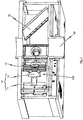
- FIG. 12 shows a perspective sectional view of an incident light attenuating device 100 according to the invention of a finite-widening beam according to one embodiment of the invention.
- FIG. The arrangement 100 is used here by way of example in a scattered-light smoke detector, which in its lower region a feed opening 60 for supplying ambient air into a (in Fig. 1 unspecified) useful light region 50 has.
- a light source which is generally designated 10.
- the light source has a light emitting diode 11 and a downstream of this LED 11 lens 12, which in turn are followed by a plurality of apertures 13, which bundle the light emitted from the light emitting diode 11 in total and introduce it into the Nutzlicht Schl.
- the Nutzlicht Scheme 50 is traversed by the unpolarized light, in the illustrated embodiment in Fig. 1 straight.
- Subordinate to the useful light region 50 in the direct beam direction of the light bundle is an absorption device 30, which serves to at least partially absorb the incident light.
- the absorber 30 has two sequentially arranged circular polarizers 31, 32 whose polarization rotation is equal to each other.
- a plurality of optical detectors 20a, 20b, 20c, 20d which serve to classify a scattered light signal possibly detected in the arrangement 100, are arranged around the useful light region 50 indicated by dashed lines.
- the optical detectors 20a, 20b, 20c, 20d have a photodiode 21a, 21b, 21c, 21d and one of these photodiode 21a, 21b, 21c, 21d downstream lens 22a, 22b, 22c, 22d, which in turn one or more apertures 23a, 23b, 23c, 23d are arranged downstream, each having a horizontally or vertically oriented linear polarization device 24a, 24b, 24c, 24d, for example, a linear polarization filter is assigned.
- Fig. 3 shows better, the exploding device 30 shown there for better illustration on a mounting device 35, which in the mounted state has a relation to the emitted light from the light source by about 45 ° in the direction of the bottom of the scattered light smoke detector inclined mounting surface.
- the circular polarization devices 31, 32 are arranged in a very small distance one behind the other, in the embodiment shown at a distance of 2 mm behind each other, which in a very effective manner, the directly incident monochromatic light of the light emitting diode 11, which bundles through the lens 12 and attenuated through the apertures 13 into the useful light region 50, so that its intensity is sufficiently small that it is not undesirably detected by the optical detectors 20a, 20b, 20c, 20d due to multiple reflection or the like.
Landscapes
- Chemical & Material Sciences (AREA)
- Analytical Chemistry (AREA)
- Physics & Mathematics (AREA)
- General Physics & Mathematics (AREA)
- Business, Economics & Management (AREA)
- Emergency Management (AREA)
- Health & Medical Sciences (AREA)
- Life Sciences & Earth Sciences (AREA)
- Biochemistry (AREA)
- General Health & Medical Sciences (AREA)
- Immunology (AREA)
- Pathology (AREA)
- Investigating Or Analysing Materials By Optical Means (AREA)
- Fire-Detection Mechanisms (AREA)
- Non-Portable Lighting Devices Or Systems Thereof (AREA)
Claims (13)
- Agencement (100) pour affaiblir de la lumière incidente d'un faisceau de rayons avec élargissement fini, de préférence de la lumière monochromatique directement incidente, dans lequel l'agencement comprend les éléments suivants :- une source de lumière (10) pour engendrer un faisceau de lumière non polarisée, de préférence de lumière monochromatique non polarisée ;- une zone de lumière utile (50) qui est traversée par la lumière non polarisée et qui s'étend en ligne droite, de préférence en partant de la source de lumière (10) ;- un dispositif d'absorption (30), agencé à la suite de la zone de lumière utile (50) et de préférence agencé à la suite dans la direction directe du rayonnement du faisceau de lumière, pour absorber au moins partiellement la lumière incidente,dans lequel le dispositif d'absorption (30) comprend au moins un dispositif de polarisation (31, 32) agencé dans la direction du faisceau de lumière.
- Agencement (100) selon la revendication 1,
dans lequel au moins un détecteur optique (20a, 20b, 20c, 20d) pour détecter la lumière diffuse est agencé tout autour de la zone de lumière utile (50). - Agencement (100) selon la revendication 1 ou 2,
dans lequel le dispositif d'absorption (30) comprend au moins deux dispositifs de polarisation (31, 32) agencés l'un à la suite de l'autre en direction du faisceau de lumière. - Agencement (100) selon la revendication 3,
dans lequel lesdits au moins deux dispositifs de polarisation (31, 32) comprennent un premier filtre de polarisation linéaire et un second filtre de polarisation linéaire, tels que les directions de polarisation du premier et du second filtre de polarisation linéaire sont décalées de 90° l'une par rapport à l'autre. - Agencement (100) selon la revendication 3,
dans lequel lesdits au moins deux dispositifs de polarisation (31, 32) comprennent un premier filtre de polarisation circulaire et un second filtre de polarisation circulaire, tels que les directions de polarisation du premier et du second filtre de polarisation circulaire sont décalées de 90° l'une par rapport à l'autre. - Agencement (100) selon la revendication 3,
dans lequel lesdits au moins deux dispositifs de polarisation (31, 32) comprennent un premier filtre de polarisation circulaire et un second filtre de polarisation circulaire, tels que le sens de rotation de la polarisation du premier filtre de polarisation en direction du faisceau de lumière incident et le sens de rotation de la polarisation du second filtre de polarisation en direction du faisceau de lumière incident sont égaux. - Agencement (100) selon la revendication 5 ou 6,
dans lequel un filtre de polarisation linéaire (21a, 21b, 21c, 21d) est associé audit au moins un détecteur optique (20a, 20b, 20c, 20d). - Agencement (100) selon l'une des revendications précédentes,
dans lequel ledit au moins un dispositif de polarisation (31, 32) est reçu de manière interchangeable dans un dispositif de maintien (35) agencé à la suite de la zone de lumière utile en direction du faisceau de lumière. - Agencement (100) selon l'une des revendications précédentes,
dans lequel la source de lumière comprend une diode électroluminescente (11) et de préférence au moins une lentille (12) ainsi que de préférence au moins un diaphragme (13). - Agencement (100) selon l'une des revendications 2 à 9,
dans lequel ledit au moins un détecteur optique comprend une photodiode et de préférence au moins une lentille ainsi que de préférence au moins un diaphragme. - Agencement (100) selon l'une des revendications 3 à 10,
dans lequel lesdits au moins deux dispositifs de polarisation sont écartés l'un de l'autre en direction du faisceau de lumière à une distance d'au moins 5 mm, de préférence d'au moins 2 mm. - Agencement selon l'une des revendications précédentes,
dans lequel ledit au moins un dispositif de polarisation est incliné par rapport à la direction du faisceau de lumière incident sous un angle, ledit angle étant formé entre le faisceau de lumière incidente et un plan de détecteur à l'intérieur duquel est agencé l'axe médian optique dudit au moins un détecteur, et l'angle s'élève de préférence à environ 45°. - Détecteur de fumée à lumière diffuse, comprenant au moins une ouverture d'admission pour admettre de l'air environnant, et comprenant un agencement selon l'une des revendications 1 à 12, dans lequel l'ouverture d'admission débouche dans une zone de lumière diffuse, et dans lequel la zone de lumière diffuse correspond au moins localement à la zone de lumière utile.
Priority Applications (10)
| Application Number | Priority Date | Filing Date | Title |
|---|---|---|---|
| PL14175734.4T PL2963627T3 (pl) | 2014-07-04 | 2014-07-04 | Urządzenie do osłabiania padającego światła wiązki promieni |
| ES14175734.4T ES2587128T3 (es) | 2014-07-04 | 2014-07-04 | Disposición para atenuar luz incidente de un haz de rayos |
| EP14175734.4A EP2963627B1 (fr) | 2014-07-04 | 2014-07-04 | Agencement destiné à atténuer la lumière incidente d'un faisceau de rayons |
| MX2016014374A MX357728B (es) | 2014-07-04 | 2015-03-25 | Conjunto para atenuar la luz incidente de un haz de radiación. |
| US15/317,194 US9964486B2 (en) | 2014-07-04 | 2015-03-25 | Assembly for attenuating impinging light of a beam of radiation |
| AU2015283230A AU2015283230B2 (en) | 2014-07-04 | 2015-03-25 | Arrangement for attenuating impinging light of a beam |
| CN201580025948.5A CN106463037A (zh) | 2014-07-04 | 2015-03-25 | 用于衰减入射光束的组件 |
| RU2017102957A RU2651644C1 (ru) | 2014-07-04 | 2015-03-25 | Устройство для ослабления падающего света пучка излучения |
| CA2946921A CA2946921C (fr) | 2014-07-04 | 2015-03-25 | Systeme d'attenuation de la lumiere incidente d'un faisceau de rayons |
| PCT/EP2015/056361 WO2016000837A1 (fr) | 2014-07-04 | 2015-03-25 | Système d'atténuation de la lumière incidente d'un faisceau de rayons |
Applications Claiming Priority (1)
| Application Number | Priority Date | Filing Date | Title |
|---|---|---|---|
| EP14175734.4A EP2963627B1 (fr) | 2014-07-04 | 2014-07-04 | Agencement destiné à atténuer la lumière incidente d'un faisceau de rayons |
Publications (2)
| Publication Number | Publication Date |
|---|---|
| EP2963627A1 EP2963627A1 (fr) | 2016-01-06 |
| EP2963627B1 true EP2963627B1 (fr) | 2016-05-18 |
Family
ID=51133908
Family Applications (1)
| Application Number | Title | Priority Date | Filing Date |
|---|---|---|---|
| EP14175734.4A Active EP2963627B1 (fr) | 2014-07-04 | 2014-07-04 | Agencement destiné à atténuer la lumière incidente d'un faisceau de rayons |
Country Status (10)
| Country | Link |
|---|---|
| US (1) | US9964486B2 (fr) |
| EP (1) | EP2963627B1 (fr) |
| CN (1) | CN106463037A (fr) |
| AU (1) | AU2015283230B2 (fr) |
| CA (1) | CA2946921C (fr) |
| ES (1) | ES2587128T3 (fr) |
| MX (1) | MX357728B (fr) |
| PL (1) | PL2963627T3 (fr) |
| RU (1) | RU2651644C1 (fr) |
| WO (1) | WO2016000837A1 (fr) |
Families Citing this family (4)
| Publication number | Priority date | Publication date | Assignee | Title |
|---|---|---|---|---|
| PL2963627T3 (pl) * | 2014-07-04 | 2016-11-30 | Urządzenie do osłabiania padającego światła wiązki promieni | |
| US10852233B2 (en) * | 2016-06-15 | 2020-12-01 | Kidde Technologies, Inc. | Systems and methods for chamberless smoke detection and indoor air quality monitoring |
| US10871452B2 (en) * | 2016-06-15 | 2020-12-22 | Kidde Technologies, Inc. | Systems and methods for chamberless smoke detection and indoor air quality monitoring |
| CN111610206B (zh) * | 2020-06-23 | 2021-03-30 | 中国科学院高能物理研究所 | 一种相干x光保护、监测与智能衰减一体化集成装置 |
Family Cites Families (21)
| Publication number | Priority date | Publication date | Assignee | Title |
|---|---|---|---|---|
| US5502434A (en) * | 1992-05-29 | 1996-03-26 | Hockiki Kabushiki Kaisha | Smoke sensor |
| CH684556A5 (de) * | 1992-09-14 | 1994-10-14 | Cerberus Ag | Optischer Rauchmelder. |
| US5576697A (en) * | 1993-04-30 | 1996-11-19 | Hochiki Kabushiki Kaisha | Fire alarm system |
| AUPQ553800A0 (en) * | 2000-02-10 | 2000-03-02 | Cole, Martin Terence | Improvements relating to smoke detectors particularily duct monitored smoke detectors |
| US6909459B2 (en) * | 2002-08-21 | 2005-06-21 | Alpha Innotech Corporation | Method of and apparatus for extending signal ranges of digital images |
| EP1647136A4 (fr) * | 2003-06-09 | 2009-07-08 | Wavien Inc | Moteur de projection a conducteur de lumiere |
| US7268881B2 (en) * | 2004-02-17 | 2007-09-11 | The Curators Of The University Of Missouri | Light scattering detector |
| US7253902B2 (en) * | 2004-03-31 | 2007-08-07 | Mitutoyo Corporation | Wavelength detector |
| US20070021807A1 (en) * | 2005-07-20 | 2007-01-25 | Eastman Kodak Company | Device for optically stimulating collagen formation in tissue |
| DE102005045280B3 (de) | 2005-09-22 | 2006-12-28 | Leuze Electronic Gmbh & Co Kg | Distanzsensor |
| US20070153122A1 (en) * | 2005-12-30 | 2007-07-05 | Ayite Nii A | Apparatus and method for simultaneous multiple video channel viewing |
| KR100802199B1 (ko) * | 2006-05-25 | 2008-03-17 | 정경희 | 광모듈 및 그 제조방법 |
| US7669457B2 (en) * | 2007-07-24 | 2010-03-02 | Honeywell International Inc. | Apparatus and method of smoke detection |
| US7852475B2 (en) * | 2007-08-13 | 2010-12-14 | Jds Uniphase Corporation | Scanning spectrometer with multiple photodetectors |
| DE102007055771A1 (de) * | 2007-12-12 | 2009-06-18 | Hilti Aktiengesellschaft | Laserdistanzmesser |
| US8390806B1 (en) * | 2009-05-21 | 2013-03-05 | Lockheed Martin Corporation | MEMS spectrometer and sensing systems therefrom |
| WO2011115293A1 (fr) * | 2010-03-19 | 2011-09-22 | 古河電気工業株式会社 | Dispositif de conversion de longueur d'onde indépendant de la polarisation et procédé de conversion de longueur d'onde indépendant de la polarisation |
| KR20120074558A (ko) * | 2010-12-28 | 2012-07-06 | 삼성전자주식회사 | 미세입자 검출장치 |
| US9995623B2 (en) * | 2013-03-14 | 2018-06-12 | Integrated Plasmonics Corporation | Ambient light assisted spectroscopy |
| TWI507742B (zh) * | 2013-11-26 | 2015-11-11 | E Ink Holdings Inc | 彩色濾光基板以及顯示裝置 |
| PL2963627T3 (pl) * | 2014-07-04 | 2016-11-30 | Urządzenie do osłabiania padającego światła wiązki promieni |
-
2014
- 2014-07-04 PL PL14175734.4T patent/PL2963627T3/pl unknown
- 2014-07-04 ES ES14175734.4T patent/ES2587128T3/es active Active
- 2014-07-04 EP EP14175734.4A patent/EP2963627B1/fr active Active
-
2015
- 2015-03-25 CN CN201580025948.5A patent/CN106463037A/zh active Pending
- 2015-03-25 RU RU2017102957A patent/RU2651644C1/ru active
- 2015-03-25 CA CA2946921A patent/CA2946921C/fr active Active
- 2015-03-25 WO PCT/EP2015/056361 patent/WO2016000837A1/fr not_active Ceased
- 2015-03-25 MX MX2016014374A patent/MX357728B/es active IP Right Grant
- 2015-03-25 US US15/317,194 patent/US9964486B2/en active Active
- 2015-03-25 AU AU2015283230A patent/AU2015283230B2/en not_active Ceased
Also Published As
| Publication number | Publication date |
|---|---|
| US20170153177A1 (en) | 2017-06-01 |
| EP2963627A1 (fr) | 2016-01-06 |
| WO2016000837A1 (fr) | 2016-01-07 |
| MX357728B (es) | 2018-07-20 |
| AU2015283230B2 (en) | 2018-06-14 |
| CA2946921A1 (fr) | 2016-01-07 |
| MX2016014374A (es) | 2017-01-20 |
| CA2946921C (fr) | 2019-01-15 |
| CN106463037A (zh) | 2017-02-22 |
| PL2963627T3 (pl) | 2016-11-30 |
| ES2587128T3 (es) | 2016-10-20 |
| US9964486B2 (en) | 2018-05-08 |
| AU2015283230A1 (en) | 2016-11-10 |
| RU2651644C1 (ru) | 2018-04-23 |
Similar Documents
| Publication | Publication Date | Title |
|---|---|---|
| DE102015207289B4 (de) | Partikelsensorvorrichtung | |
| DE102011113147B3 (de) | Vorrichtung zur optischen Abstandsmessung | |
| EP2836818B1 (fr) | Système de détection de gaz | |
| EP3521810A1 (fr) | Appareil d'analyse permettant de déterminer la fines poussières | |
| DE102019209213A1 (de) | Sensoranordnung zur Charakterisierung von Partikeln | |
| EP2963627B1 (fr) | Agencement destiné à atténuer la lumière incidente d'un faisceau de rayons | |
| DE102016125401A1 (de) | Teilchensensor | |
| EP3583445A1 (fr) | Capteur lidar servant à détecter un objet | |
| DE10247136A1 (de) | Schutzvorrichtung zur Überwachung eines mit einem Bauteil zu bewegenden Schutzbereichs | |
| EP2157449B1 (fr) | Barrière lumineuse | |
| EP2093731A1 (fr) | Détecteur de fumée optique linéaire doté de plusieurs rayons partiels | |
| EP3096130B1 (fr) | Dispositif destine a l'identification d'aerosols | |
| DE202009007612U1 (de) | Reflexionslichtschrankensensor | |
| DE102018212823A1 (de) | LIDAR-Vorrichtung zur Erfassung eines Objektes | |
| EP3704473A1 (fr) | Capteur novateur pour spectroscopie raman | |
| DE4122305A1 (de) | Vorrichtung zur optoelektronischen abtastung eines fadens | |
| EP1780559B1 (fr) | Capteur optique | |
| EP1574880B2 (fr) | Émetteur pour barrière lumineuse, rideau optique ou équivalent | |
| DE102012100746B4 (de) | Sendeeinheit für einen optischen Sensor | |
| DE102018114389A1 (de) | Laserscanner für ein Fahrunterstützungssystem und Fahrunterstützungssystem aufweisend einen Laserscanner | |
| EP3743710B1 (fr) | Système de détection optique pour détecter une substance dans une région de mesure | |
| DD294794A5 (de) | Vorrichtung zur messung von aerosolen und in luft verteiltem staub | |
| DE102021112212A1 (de) | Optischer Sensor und Verfahren zum Betrieb eines optische Sensors | |
| EP3353592B1 (fr) | Dispositif de mesure de distance | |
| EP2216661A1 (fr) | Capteur optique destiné au contrôle d'objets dans une zone de surveillance |
Legal Events
| Date | Code | Title | Description |
|---|---|---|---|
| PUAI | Public reference made under article 153(3) epc to a published international application that has entered the european phase |
Free format text: ORIGINAL CODE: 0009012 |
|
| 17P | Request for examination filed |
Effective date: 20150303 |
|
| AK | Designated contracting states |
Kind code of ref document: A1 Designated state(s): AL AT BE BG CH CY CZ DE DK EE ES FI FR GB GR HR HU IE IS IT LI LT LU LV MC MK MT NL NO PL PT RO RS SE SI SK SM TR |
|
| AX | Request for extension of the european patent |
Extension state: BA ME |
|
| GRAP | Despatch of communication of intention to grant a patent |
Free format text: ORIGINAL CODE: EPIDOSNIGR1 |
|
| INTG | Intention to grant announced |
Effective date: 20160120 |
|
| GRAS | Grant fee paid |
Free format text: ORIGINAL CODE: EPIDOSNIGR3 |
|
| GRAA | (expected) grant |
Free format text: ORIGINAL CODE: 0009210 |
|
| AK | Designated contracting states |
Kind code of ref document: B1 Designated state(s): AL AT BE BG CH CY CZ DE DK EE ES FI FR GB GR HR HU IE IS IT LI LT LU LV MC MK MT NL NO PL PT RO RS SE SI SK SM TR |
|
| REG | Reference to a national code |
Ref country code: GB Ref legal event code: FG4D Free format text: NOT ENGLISH |
|
| REG | Reference to a national code |
Ref country code: CH Ref legal event code: EP |
|
| REG | Reference to a national code |
Ref country code: AT Ref legal event code: REF Ref document number: 801072 Country of ref document: AT Kind code of ref document: T Effective date: 20160615 Ref country code: IE Ref legal event code: FG4D Free format text: LANGUAGE OF EP DOCUMENT: GERMAN |
|
| REG | Reference to a national code |
Ref country code: DE Ref legal event code: R096 Ref document number: 502014000790 Country of ref document: DE |
|
| REG | Reference to a national code |
Ref country code: CH Ref legal event code: NV Representative=s name: FIAMMENGHI-FIAMMENGHI, CH |
|
| REG | Reference to a national code |
Ref country code: FR Ref legal event code: PLFP Year of fee payment: 3 |
|
| REG | Reference to a national code |
Ref country code: NL Ref legal event code: FP |
|
| REG | Reference to a national code |
Ref country code: LT Ref legal event code: MG4D |
|
| REG | Reference to a national code |
Ref country code: ES Ref legal event code: FG2A Ref document number: 2587128 Country of ref document: ES Kind code of ref document: T3 Effective date: 20161020 |
|
| PG25 | Lapsed in a contracting state [announced via postgrant information from national office to epo] |
Ref country code: NO Free format text: LAPSE BECAUSE OF FAILURE TO SUBMIT A TRANSLATION OF THE DESCRIPTION OR TO PAY THE FEE WITHIN THE PRESCRIBED TIME-LIMIT Effective date: 20160818 Ref country code: FI Free format text: LAPSE BECAUSE OF FAILURE TO SUBMIT A TRANSLATION OF THE DESCRIPTION OR TO PAY THE FEE WITHIN THE PRESCRIBED TIME-LIMIT Effective date: 20160518 Ref country code: LT Free format text: LAPSE BECAUSE OF FAILURE TO SUBMIT A TRANSLATION OF THE DESCRIPTION OR TO PAY THE FEE WITHIN THE PRESCRIBED TIME-LIMIT Effective date: 20160518 |
|
| PG25 | Lapsed in a contracting state [announced via postgrant information from national office to epo] |
Ref country code: SE Free format text: LAPSE BECAUSE OF FAILURE TO SUBMIT A TRANSLATION OF THE DESCRIPTION OR TO PAY THE FEE WITHIN THE PRESCRIBED TIME-LIMIT Effective date: 20160518 Ref country code: LV Free format text: LAPSE BECAUSE OF FAILURE TO SUBMIT A TRANSLATION OF THE DESCRIPTION OR TO PAY THE FEE WITHIN THE PRESCRIBED TIME-LIMIT Effective date: 20160518 Ref country code: HR Free format text: LAPSE BECAUSE OF FAILURE TO SUBMIT A TRANSLATION OF THE DESCRIPTION OR TO PAY THE FEE WITHIN THE PRESCRIBED TIME-LIMIT Effective date: 20160518 Ref country code: PT Free format text: LAPSE BECAUSE OF FAILURE TO SUBMIT A TRANSLATION OF THE DESCRIPTION OR TO PAY THE FEE WITHIN THE PRESCRIBED TIME-LIMIT Effective date: 20160919 Ref country code: RS Free format text: LAPSE BECAUSE OF FAILURE TO SUBMIT A TRANSLATION OF THE DESCRIPTION OR TO PAY THE FEE WITHIN THE PRESCRIBED TIME-LIMIT Effective date: 20160518 Ref country code: GR Free format text: LAPSE BECAUSE OF FAILURE TO SUBMIT A TRANSLATION OF THE DESCRIPTION OR TO PAY THE FEE WITHIN THE PRESCRIBED TIME-LIMIT Effective date: 20160819 |
|
| PG25 | Lapsed in a contracting state [announced via postgrant information from national office to epo] |
Ref country code: RO Free format text: LAPSE BECAUSE OF FAILURE TO SUBMIT A TRANSLATION OF THE DESCRIPTION OR TO PAY THE FEE WITHIN THE PRESCRIBED TIME-LIMIT Effective date: 20160518 Ref country code: SK Free format text: LAPSE BECAUSE OF FAILURE TO SUBMIT A TRANSLATION OF THE DESCRIPTION OR TO PAY THE FEE WITHIN THE PRESCRIBED TIME-LIMIT Effective date: 20160518 Ref country code: CZ Free format text: LAPSE BECAUSE OF FAILURE TO SUBMIT A TRANSLATION OF THE DESCRIPTION OR TO PAY THE FEE WITHIN THE PRESCRIBED TIME-LIMIT Effective date: 20160518 Ref country code: DK Free format text: LAPSE BECAUSE OF FAILURE TO SUBMIT A TRANSLATION OF THE DESCRIPTION OR TO PAY THE FEE WITHIN THE PRESCRIBED TIME-LIMIT Effective date: 20160518 Ref country code: EE Free format text: LAPSE BECAUSE OF FAILURE TO SUBMIT A TRANSLATION OF THE DESCRIPTION OR TO PAY THE FEE WITHIN THE PRESCRIBED TIME-LIMIT Effective date: 20160518 |
|
| REG | Reference to a national code |
Ref country code: DE Ref legal event code: R097 Ref document number: 502014000790 Country of ref document: DE |
|
| PG25 | Lapsed in a contracting state [announced via postgrant information from national office to epo] |
Ref country code: SM Free format text: LAPSE BECAUSE OF FAILURE TO SUBMIT A TRANSLATION OF THE DESCRIPTION OR TO PAY THE FEE WITHIN THE PRESCRIBED TIME-LIMIT Effective date: 20160518 |
|
| PLBE | No opposition filed within time limit |
Free format text: ORIGINAL CODE: 0009261 |
|
| STAA | Information on the status of an ep patent application or granted ep patent |
Free format text: STATUS: NO OPPOSITION FILED WITHIN TIME LIMIT |
|
| PG25 | Lapsed in a contracting state [announced via postgrant information from national office to epo] |
Ref country code: MC Free format text: LAPSE BECAUSE OF FAILURE TO SUBMIT A TRANSLATION OF THE DESCRIPTION OR TO PAY THE FEE WITHIN THE PRESCRIBED TIME-LIMIT Effective date: 20160518 |
|
| 26N | No opposition filed |
Effective date: 20170221 |
|
| REG | Reference to a national code |
Ref country code: IE Ref legal event code: MM4A |
|
| PG25 | Lapsed in a contracting state [announced via postgrant information from national office to epo] |
Ref country code: SI Free format text: LAPSE BECAUSE OF FAILURE TO SUBMIT A TRANSLATION OF THE DESCRIPTION OR TO PAY THE FEE WITHIN THE PRESCRIBED TIME-LIMIT Effective date: 20160518 |
|
| REG | Reference to a national code |
Ref country code: FR Ref legal event code: PLFP Year of fee payment: 4 |
|
| PG25 | Lapsed in a contracting state [announced via postgrant information from national office to epo] |
Ref country code: IE Free format text: LAPSE BECAUSE OF NON-PAYMENT OF DUE FEES Effective date: 20160704 |
|
| PG25 | Lapsed in a contracting state [announced via postgrant information from national office to epo] |
Ref country code: LU Free format text: LAPSE BECAUSE OF NON-PAYMENT OF DUE FEES Effective date: 20160704 |
|
| PG25 | Lapsed in a contracting state [announced via postgrant information from national office to epo] |
Ref country code: HU Free format text: LAPSE BECAUSE OF FAILURE TO SUBMIT A TRANSLATION OF THE DESCRIPTION OR TO PAY THE FEE WITHIN THE PRESCRIBED TIME-LIMIT; INVALID AB INITIO Effective date: 20140704 |
|
| PG25 | Lapsed in a contracting state [announced via postgrant information from national office to epo] |
Ref country code: MT Free format text: LAPSE BECAUSE OF FAILURE TO SUBMIT A TRANSLATION OF THE DESCRIPTION OR TO PAY THE FEE WITHIN THE PRESCRIBED TIME-LIMIT Effective date: 20160518 Ref country code: IS Free format text: LAPSE BECAUSE OF FAILURE TO SUBMIT A TRANSLATION OF THE DESCRIPTION OR TO PAY THE FEE WITHIN THE PRESCRIBED TIME-LIMIT Effective date: 20160518 Ref country code: MK Free format text: LAPSE BECAUSE OF FAILURE TO SUBMIT A TRANSLATION OF THE DESCRIPTION OR TO PAY THE FEE WITHIN THE PRESCRIBED TIME-LIMIT Effective date: 20160518 Ref country code: CY Free format text: LAPSE BECAUSE OF FAILURE TO SUBMIT A TRANSLATION OF THE DESCRIPTION OR TO PAY THE FEE WITHIN THE PRESCRIBED TIME-LIMIT Effective date: 20160518 |
|
| REG | Reference to a national code |
Ref country code: FR Ref legal event code: PLFP Year of fee payment: 5 |
|
| PG25 | Lapsed in a contracting state [announced via postgrant information from national office to epo] |
Ref country code: BG Free format text: LAPSE BECAUSE OF FAILURE TO SUBMIT A TRANSLATION OF THE DESCRIPTION OR TO PAY THE FEE WITHIN THE PRESCRIBED TIME-LIMIT Effective date: 20160518 |
|
| PG25 | Lapsed in a contracting state [announced via postgrant information from national office to epo] |
Ref country code: AL Free format text: LAPSE BECAUSE OF FAILURE TO SUBMIT A TRANSLATION OF THE DESCRIPTION OR TO PAY THE FEE WITHIN THE PRESCRIBED TIME-LIMIT Effective date: 20160518 |
|
| P01 | Opt-out of the competence of the unified patent court (upc) registered |
Effective date: 20230526 |
|
| PGFP | Annual fee paid to national office [announced via postgrant information from national office to epo] |
Ref country code: NL Payment date: 20230719 Year of fee payment: 10 |
|
| PGFP | Annual fee paid to national office [announced via postgrant information from national office to epo] |
Ref country code: IT Payment date: 20230724 Year of fee payment: 10 Ref country code: ES Payment date: 20230926 Year of fee payment: 10 |
|
| PGFP | Annual fee paid to national office [announced via postgrant information from national office to epo] |
Ref country code: FR Payment date: 20230726 Year of fee payment: 10 Ref country code: BE Payment date: 20230719 Year of fee payment: 10 |
|
| PGFP | Annual fee paid to national office [announced via postgrant information from national office to epo] |
Ref country code: PL Payment date: 20240621 Year of fee payment: 11 |
|
| PGFP | Annual fee paid to national office [announced via postgrant information from national office to epo] |
Ref country code: TR Payment date: 20240624 Year of fee payment: 11 |
|
| PGFP | Annual fee paid to national office [announced via postgrant information from national office to epo] |
Ref country code: GB Payment date: 20240725 Year of fee payment: 11 |
|
| PGFP | Annual fee paid to national office [announced via postgrant information from national office to epo] |
Ref country code: CH Payment date: 20240801 Year of fee payment: 11 |
|
| PGFP | Annual fee paid to national office [announced via postgrant information from national office to epo] |
Ref country code: AT Payment date: 20240722 Year of fee payment: 11 |
|
| REG | Reference to a national code |
Ref country code: NL Ref legal event code: MM Effective date: 20240801 |
|
| PG25 | Lapsed in a contracting state [announced via postgrant information from national office to epo] |
Ref country code: NL Free format text: LAPSE BECAUSE OF NON-PAYMENT OF DUE FEES Effective date: 20240801 |
|
| PG25 | Lapsed in a contracting state [announced via postgrant information from national office to epo] |
Ref country code: BE Free format text: LAPSE BECAUSE OF NON-PAYMENT OF DUE FEES Effective date: 20240731 |
|
| PG25 | Lapsed in a contracting state [announced via postgrant information from national office to epo] |
Ref country code: FR Free format text: LAPSE BECAUSE OF NON-PAYMENT OF DUE FEES Effective date: 20240731 |
|
| REG | Reference to a national code |
Ref country code: BE Ref legal event code: MM Effective date: 20240731 |
|
| REG | Reference to a national code |
Ref country code: DE Ref legal event code: R081 Ref document number: 502014000790 Country of ref document: DE Owner name: WAGNER GROUP GMBH, DE Free format text: FORMER OWNER: AMRONA AG, ZUG, CH |
|
| PG25 | Lapsed in a contracting state [announced via postgrant information from national office to epo] |
Ref country code: IT Free format text: LAPSE BECAUSE OF NON-PAYMENT OF DUE FEES Effective date: 20240704 |
|
| REG | Reference to a national code |
Ref country code: ES Ref legal event code: FD2A Effective date: 20250828 |
|
| PG25 | Lapsed in a contracting state [announced via postgrant information from national office to epo] |
Ref country code: ES Free format text: LAPSE BECAUSE OF NON-PAYMENT OF DUE FEES Effective date: 20240705 |
|
| PGFP | Annual fee paid to national office [announced via postgrant information from national office to epo] |
Ref country code: DE Payment date: 20250722 Year of fee payment: 12 |
|
| REG | Reference to a national code |
Ref country code: CH Ref legal event code: H13 Free format text: ST27 STATUS EVENT CODE: U-0-0-H10-H13 (AS PROVIDED BY THE NATIONAL OFFICE) Effective date: 20260224 |
|
| REG | Reference to a national code |
Ref country code: AT Ref legal event code: MM01 Ref document number: 801072 Country of ref document: AT Kind code of ref document: T Effective date: 20250704 |
|
| GBPC | Gb: european patent ceased through non-payment of renewal fee |
Effective date: 20250704 |
|
| PG25 | Lapsed in a contracting state [announced via postgrant information from national office to epo] |
Ref country code: GB Free format text: LAPSE BECAUSE OF NON-PAYMENT OF DUE FEES Effective date: 20250704 |
|
| PG25 | Lapsed in a contracting state [announced via postgrant information from national office to epo] |
Ref country code: AT Free format text: LAPSE BECAUSE OF NON-PAYMENT OF DUE FEES Effective date: 20250704 |
|
| PG25 | Lapsed in a contracting state [announced via postgrant information from national office to epo] |
Ref country code: CH Free format text: LAPSE BECAUSE OF NON-PAYMENT OF DUE FEES Effective date: 20250731 |