EP2963704A1 - Batterie secondaire au lithium à l'état solide et son procedé de fabrication - Google Patents
Batterie secondaire au lithium à l'état solide et son procedé de fabrication Download PDFInfo
- Publication number
- EP2963704A1 EP2963704A1 EP15174022.2A EP15174022A EP2963704A1 EP 2963704 A1 EP2963704 A1 EP 2963704A1 EP 15174022 A EP15174022 A EP 15174022A EP 2963704 A1 EP2963704 A1 EP 2963704A1
- Authority
- EP
- European Patent Office
- Prior art keywords
- solid electrolyte
- electrolyte layer
- current collector
- outer periphery
- anode current
- Prior art date
- Legal status (The legal status is an assumption and is not a legal conclusion. Google has not performed a legal analysis and makes no representation as to the accuracy of the status listed.)
- Withdrawn
Links
Images



Classifications
-
- H—ELECTRICITY
- H01—ELECTRIC ELEMENTS
- H01M—PROCESSES OR MEANS, e.g. BATTERIES, FOR THE DIRECT CONVERSION OF CHEMICAL ENERGY INTO ELECTRICAL ENERGY
- H01M10/00—Secondary cells; Manufacture thereof
- H01M10/02—Details
-
- H—ELECTRICITY
- H01—ELECTRIC ELEMENTS
- H01M—PROCESSES OR MEANS, e.g. BATTERIES, FOR THE DIRECT CONVERSION OF CHEMICAL ENERGY INTO ELECTRICAL ENERGY
- H01M4/00—Electrodes
- H01M4/02—Electrodes composed of, or comprising, active material
- H01M4/13—Electrodes for accumulators with non-aqueous electrolyte, e.g. for lithium-accumulators; Processes of manufacture thereof
- H01M4/134—Electrodes based on metals, Si or alloys
-
- H—ELECTRICITY
- H01—ELECTRIC ELEMENTS
- H01M—PROCESSES OR MEANS, e.g. BATTERIES, FOR THE DIRECT CONVERSION OF CHEMICAL ENERGY INTO ELECTRICAL ENERGY
- H01M10/00—Secondary cells; Manufacture thereof
- H01M10/05—Accumulators with non-aqueous electrolyte
- H01M10/052—Li-accumulators
-
- H—ELECTRICITY
- H01—ELECTRIC ELEMENTS
- H01M—PROCESSES OR MEANS, e.g. BATTERIES, FOR THE DIRECT CONVERSION OF CHEMICAL ENERGY INTO ELECTRICAL ENERGY
- H01M10/00—Secondary cells; Manufacture thereof
- H01M10/05—Accumulators with non-aqueous electrolyte
- H01M10/056—Accumulators with non-aqueous electrolyte characterised by the materials used as electrolytes, e.g. mixed inorganic/organic electrolytes
- H01M10/0561—Accumulators with non-aqueous electrolyte characterised by the materials used as electrolytes, e.g. mixed inorganic/organic electrolytes the electrolyte being constituted of inorganic materials only
- H01M10/0562—Solid materials
-
- H—ELECTRICITY
- H01—ELECTRIC ELEMENTS
- H01M—PROCESSES OR MEANS, e.g. BATTERIES, FOR THE DIRECT CONVERSION OF CHEMICAL ENERGY INTO ELECTRICAL ENERGY
- H01M10/00—Secondary cells; Manufacture thereof
- H01M10/05—Accumulators with non-aqueous electrolyte
- H01M10/058—Construction or manufacture
-
- H—ELECTRICITY
- H01—ELECTRIC ELEMENTS
- H01M—PROCESSES OR MEANS, e.g. BATTERIES, FOR THE DIRECT CONVERSION OF CHEMICAL ENERGY INTO ELECTRICAL ENERGY
- H01M10/00—Secondary cells; Manufacture thereof
- H01M10/05—Accumulators with non-aqueous electrolyte
- H01M10/058—Construction or manufacture
- H01M10/0585—Construction or manufacture of accumulators having only flat construction elements, i.e. flat positive electrodes, flat negative electrodes and flat separators
-
- H—ELECTRICITY
- H01—ELECTRIC ELEMENTS
- H01M—PROCESSES OR MEANS, e.g. BATTERIES, FOR THE DIRECT CONVERSION OF CHEMICAL ENERGY INTO ELECTRICAL ENERGY
- H01M10/00—Secondary cells; Manufacture thereof
- H01M10/42—Methods or arrangements for servicing or maintenance of secondary cells or secondary half-cells
- H01M10/44—Methods for charging or discharging
- H01M10/446—Initial charging measures
-
- H—ELECTRICITY
- H01—ELECTRIC ELEMENTS
- H01M—PROCESSES OR MEANS, e.g. BATTERIES, FOR THE DIRECT CONVERSION OF CHEMICAL ENERGY INTO ELECTRICAL ENERGY
- H01M4/00—Electrodes
- H01M4/02—Electrodes composed of, or comprising, active material
- H01M4/13—Electrodes for accumulators with non-aqueous electrolyte, e.g. for lithium-accumulators; Processes of manufacture thereof
- H01M4/139—Processes of manufacture
- H01M4/1395—Processes of manufacture of electrodes based on metals, Si or alloys
-
- H—ELECTRICITY
- H01—ELECTRIC ELEMENTS
- H01M—PROCESSES OR MEANS, e.g. BATTERIES, FOR THE DIRECT CONVERSION OF CHEMICAL ENERGY INTO ELECTRICAL ENERGY
- H01M4/00—Electrodes
- H01M4/02—Electrodes composed of, or comprising, active material
- H01M4/36—Selection of substances as active materials, active masses, active liquids
- H01M4/38—Selection of substances as active materials, active masses, active liquids of elements or alloys
- H01M4/381—Alkaline or alkaline earth metals elements
- H01M4/382—Lithium
-
- H—ELECTRICITY
- H01—ELECTRIC ELEMENTS
- H01M—PROCESSES OR MEANS, e.g. BATTERIES, FOR THE DIRECT CONVERSION OF CHEMICAL ENERGY INTO ELECTRICAL ENERGY
- H01M2300/00—Electrolytes
- H01M2300/0017—Non-aqueous electrolytes
- H01M2300/0065—Solid electrolytes
- H01M2300/0068—Solid electrolytes inorganic
-
- Y—GENERAL TAGGING OF NEW TECHNOLOGICAL DEVELOPMENTS; GENERAL TAGGING OF CROSS-SECTIONAL TECHNOLOGIES SPANNING OVER SEVERAL SECTIONS OF THE IPC; TECHNICAL SUBJECTS COVERED BY FORMER USPC CROSS-REFERENCE ART COLLECTIONS [XRACs] AND DIGESTS
- Y02—TECHNOLOGIES OR APPLICATIONS FOR MITIGATION OR ADAPTATION AGAINST CLIMATE CHANGE
- Y02E—REDUCTION OF GREENHOUSE GAS [GHG] EMISSIONS, RELATED TO ENERGY GENERATION, TRANSMISSION OR DISTRIBUTION
- Y02E60/00—Enabling technologies; Technologies with a potential or indirect contribution to GHG emissions mitigation
- Y02E60/10—Energy storage using batteries
-
- Y—GENERAL TAGGING OF NEW TECHNOLOGICAL DEVELOPMENTS; GENERAL TAGGING OF CROSS-SECTIONAL TECHNOLOGIES SPANNING OVER SEVERAL SECTIONS OF THE IPC; TECHNICAL SUBJECTS COVERED BY FORMER USPC CROSS-REFERENCE ART COLLECTIONS [XRACs] AND DIGESTS
- Y02—TECHNOLOGIES OR APPLICATIONS FOR MITIGATION OR ADAPTATION AGAINST CLIMATE CHANGE
- Y02P—CLIMATE CHANGE MITIGATION TECHNOLOGIES IN THE PRODUCTION OR PROCESSING OF GOODS
- Y02P70/00—Climate change mitigation technologies in the production process for final industrial or consumer products
- Y02P70/50—Manufacturing or production processes characterised by the final manufactured product
-
- Y—GENERAL TAGGING OF NEW TECHNOLOGICAL DEVELOPMENTS; GENERAL TAGGING OF CROSS-SECTIONAL TECHNOLOGIES SPANNING OVER SEVERAL SECTIONS OF THE IPC; TECHNICAL SUBJECTS COVERED BY FORMER USPC CROSS-REFERENCE ART COLLECTIONS [XRACs] AND DIGESTS
- Y02—TECHNOLOGIES OR APPLICATIONS FOR MITIGATION OR ADAPTATION AGAINST CLIMATE CHANGE
- Y02T—CLIMATE CHANGE MITIGATION TECHNOLOGIES RELATED TO TRANSPORTATION
- Y02T10/00—Road transport of goods or passengers
- Y02T10/60—Other road transportation technologies with climate change mitigation effect
- Y02T10/70—Energy storage systems for electromobility, e.g. batteries
Definitions
- the present invention relates to a solid state lithium secondary battery in which the occurrence of a short circuit at the time of charging is suppressed.
- Patent Literature 1 discloses a secondary battery in which a cathode and an anode are arranged with an electrolyte disposed therebetween, the battery being configured in a state that an active material layer is not formed on an anode current collector at the time of assembling, and having alkali metals and the like precipitated on the anode current collector during charging. This technology is intended for an enhancement of the battery capacity.
- Patent Literature 2 discloses an organic solid electrolyte battery including lithium metal in the anode, in which the area of the anode is smaller than the area of the cathode. This technology is intended to provide a highly safe organic solid electrolyte battery having no lithium remaining even at the end of discharge.
- Patent Literature 3 discloses a non-aqueous electrolyte battery including a sulfide-based solid electrolyte material layer, in which an intermediate layer that suppresses mutual diffusion is included between a cathode and a solid electrolyte layer, and an anode layer is smaller than the cathode layer and the solid electrolyte layer and is larger than the intermediate layer. This technology is intended to enhance the charge-discharge cycle characteristics.
- a solid state lithium secondary battery in which an anode active material layer is not provided at the time of assembling, and lithium (Li) metal as an anode active material is precipitated by subsequent charging, has an inherent problem that short circuits caused by dendrites are prone to occur, compared with a solid state lithium secondary battery provided with an anode active material layer at the time of assembling.
- Li is inserted into the interior of the anode active material (for example, carbon), and therefore, usually Li precipitation does not instantly occur at the surface of the anode active material.
- an anode active material layer is not provided at the time of assembling, Li precipitation occurs on the surface of the anode current collector at the time of charging, and therefore, short circuits caused by dendrites are likely to occur.
- a solid state lithium secondary battery having a solid electrolyte layer containing sulfide solid electrolyte particles has an intrinsic problem that short circuits caused by dendrites are prone to occur, compared with a solid state lithium secondary battery having, for example, a thin film type solid electrolyte layer formed by a vapor deposition method or the like. Since it is difficult to impart, to a pressed powder type solid electrolyte layer, a denseness equal to that of a thin film type solid electrolyte layer, short circuits caused by dendrites are highly prone to occur in such circumstances. Particularly, when the thickness of the pressed powder type solid electrolyte layer is made smaller, short circuits occur more conspicuously.
- the present invention has been made under such circumstances, and it is a main object of the invention to provide a solid state lithium secondary battery in which the occurrence of a short circuit at the time of charging is suppressed.
- the inventors of the present invention conducted thorough investigations, and as a result, the inventors found that when the thickness of the pressed powder type solid electrolyte layer is small, the outer periphery of the solid electrolyte layer is in a circumstance that dendrites are particularly prone to occur. Therefore, the inventors found that when the distance from the outer periphery of the solid electrolyte layer to the outer periphery of an anode current collector is increased, the occurrence of a short circuit at the time of charging can be suppressed, and thus the inventors completed the invention.
- a solid state lithium secondary battery comprising an anode current collector, a solid electrolyte layer, a cathode active material layer and a cathode current collector in this order, wherein the solid electrolyte layer is provided on a surface of the anode current collector, the solid electrolyte layer contains a sulfide solid electrolyte particle, a thickness of the solid electrolyte layer is 50 ⁇ m or less, an outer periphery of the anode current collector is formed inwardly of an outer periphery of the solid electrolyte layer when viewed in a planar view, and a distance between the outer periphery of the solid electrolyte layer and the outer periphery of the anode current collector is 300 ⁇ m or more.
- the outer periphery of the anode current collector is formed inwardly of the outer periphery of the solid electrolyte layer, and the distance between the two is larger than or equal to a predetermined value, a solid state lithium secondary battery in which the occurrence of a short circuit at the time of charging is suppressed, can be obtained.
- a solid state lithium secondary battery comprising an anode current collector, a solid electrolyte layer, a cathode active material layer, and a cathode current collector in this order, wherein the solid state lithium secondary battery comprises an anode active material layer composed of precipitated Li metal on a surface on the solid electrolyte layer side of the anode current collector, the solid electrolyte layer contains a sulfide solid electrolyte particle, a thickness of the solid electrolyte layer is 50 ⁇ m or less, an outer periphery of the anode current collector is formed inwardly of an outer periphery of the solid electrolyte layer when viewed in a planar view, and a distance between the outer periphery of the solid electrolyte layer and the outer periphery of the anode current collector is 300 ⁇ m or more.
- the outer periphery of the anode current collector is formed inwardly of the outer periphery of the solid electrolyte layer, and the distance between the two is larger than or equal to a predetermined value, a solid state lithium secondary battery in which the occurrence of a short circuit at the time of charging is suppressed, can be obtained.
- the distance between the outer periphery of the solid electrolyte layer and the outer periphery of the anode current collector be 640 ⁇ m or more.
- a method for producing a solid state lithium secondary battery comprising steps of: a preparation step of preparing a laminate including an anode current collector, a solid electrolyte layer, a cathode active material layer and a cathode current collector in this order; and a charging step of subjecting the laminate to a charging treatment, wherein in the preparation step, at least the solid electrolyte layer is formed by a pressurization treatment, in the charging step, an anode active material layer composed of precipitated Li metal is formed on a surface on the solid electrolyte layer side of the anode current collector by causing Li contained in the cathode active material layer to migrate toward the anode current collector side, the solid electrolyte layer contains a sulfide solid electrolyte particle, a thickness of the solid electrolyte layer is 50 ⁇ m or less, when viewed in a planar view, an outer periphery of the anode current collector is formed inward
- the outer periphery of the anode current collector is formed inwardly of the outer periphery of the solid electrolyte layer, and the distance between the two is larger than or equal to a predetermined value, a solid state lithium secondary battery in which the occurrence of a short circuit at the time of charging is suppressed, can be obtained.
- the solid state lithium secondary battery of the invention gives an effect that the occurrence of a short circuit at the time of charging can be suppressed.
- the solid state lithium secondary battery of the invention can be roughly divided into two embodiments.
- the solid state lithium secondary battery is explained separately as a first embodiment and a second embodiment.
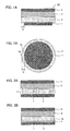
- FIGS. 1A and 1B are schematic diagrams illustrating an example of the solid state lithium secondary battery of the first embodiment. Specifically, FIG. 1A is an outline cross-sectional diagram of a solid state lithium secondary battery, and FIG. 1B is an outline plan view diagram viewing the solid state lithium secondary battery from the anode current collector side.
- the solid state lithium secondary battery 10 of the first embodiment comprises an anode current collector 1, a solid electrolyte layer 2, a cathode active material layer 3, and a cathode current collector 4 in this order.
- the solid electrolyte layer 2 is disposed on the surface of the anode current collector 1, and the two are in contact.
- the solid electrolyte layer 2 contains sulfide solid electrolyte particles (not shown in the diagram), and the thickness of the solid electrolyte layer 2 is 50 ⁇ m or less. Furthermore, as illustrated in FIG.
- the outer periphery of the anode current collector 1 is formed inwardly of the outer periphery of the solid electrolyte layer 2 when viewed in a planar view.
- the solid state lithium secondary battery is designed such that the distance D between the outer periphery of the anode current collector 1 and the outer periphery of the solid electrolyte layer 2 is larger than or equal to a predetermined value.
- the distance D when a point on the outer periphery of the solid electrolyte layer 2 is defined as an outer peripheral section 2a, the distance D means the distance from the outer peripheral section 2a to a point in the shortest distance on the outer periphery of the anode current collector 1 (outer peripheral section 1a). Furthermore, according to the first embodiment, it is preferable that the distance D be larger than or equal to a predetermined value in the substantially entire region of the solid electrolyte layer 2.
- the substantially entire region means 80% or more of the entire outer periphery of the solid electrolyte layer 2, and the substantially entire region is preferably 90% or more, and more preferably 95% or more.
- the distance D be larger than or equal to a predetermined value.
- the distance D is larger than or equal to a predetermined value in 80% or more of the entire outer periphery of the solid electrolyte layer 2, the occurrence of dendrites can be suppressed at a high probability.
- the outer periphery of the anode current collector is formed inwardly of the outer periphery of the solid electrolyte layer, and the distance between the two is larger than or equal to a predetermined value, a solid state lithium secondary battery in which the occurrence of a short circuit at the time of charging is suppressed, can be obtained. Furthermore, as described above, in the first embodiment, in a case where the thickness of the solid electrolyte layer is small, the outer periphery of the solid electrolyte layer is in a circumstance that particularly dendrites are likely to be generated. The reason for this is speculated to be as follows.
- voids are likely to remain in the outer periphery of the solid electrolyte layer by pressurization and depressurization during molding.
- sulfide solid electrolyte particles are added to a molding tool (mold), and molding is carried out by pressing the electrolyte particles with a piston and the like.
- force works from the central section toward the outer peripheral section, and the outer peripheral section of the solid electrolyte layer is in a dense state.
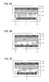
- FIGS. 2A and 2B are outline cross-sectional diagrams explaining the mechanism of a short circuit.
- Li contained in the cathode active material layer 3 migrates toward the anode current collector 1 at the time of charging.
- an anode active material layer 5, which is precipitated Li metal is formed on the surface on the side of the solid electrolyte layer 2 of the anode current collector 1.
- dendrites 5a are likely to be generated in the outer periphery of the solid electrolyte layer 2, and a short circuit is prone to occur.
- the solid state lithium secondary battery of the first embodiment does not have an anode active material (Li metal) in the stage before charging (upon battery assembling), and causes precipitation and self-formation of an anode active material (Li metal) using the Li contained in the cathode active material layer at the time of charging. Therefore, it is advantageous in terms of volume and weight as compared with the case where an anode active material layer has been prepared in advance, and an increase in the energy density of the battery can be promoted. Furthermore, since the amount of Li metal used in the battery can be minimized, reactions derived from Li metal occur to a relatively reduced extent.
- the solid electrolyte layer contains sulfide solid electrolyte particles.
- a solid electrolyte layer can be obtained by pressurizing sulfide solid electrolyte particles (powder pressing).
- the thickness of the solid electrolyte layer is usually 50 ⁇ m or less, preferably 30 ⁇ m or less, and more preferably 20 ⁇ m or less.
- the thickness of the solid electrolyte layer is, for example, 1 ⁇ m or more, and preferably 10 ⁇ m or more.
- the thickness of the solid electrolyte layer refers to the average thickness of the solid electrolyte layer.
- Examples of the sulfide solid electrolyte particles include particles of Li 2 S-P 2 S 5 , Li 2 S-P 2 S 5 -LiI, Li 2 S-P 2 S 5 -LiCl, Li 2 S-P 2 S 5 -LiBr, Li 2 S-P 2 S 5 -Li 2 O, Li 2 S-P 2 S 5 -Li 2 O-LiI, Li 2 S-SiS 2 , Li 2 S-SiS 2 -LiI, Li 2 S-SiS 2 -LiBr, Li 2 S-SiS 2 -LiCl, Li 2 S-SiS 2 -B 2 S 3 -LiI, Li 2 S-SiS 2 -P 2 S 5 -LiI, Li 2 S-B 2 S 3 , Li 2 S-P 2 S 5 -Z m S n (provided that m and n represent positive numbers; and Z represents any of Ge, Zn and Ga), Li 2 S-
- the sulfide solid electrolyte particles may be amorphous or may be crystalline, or may be made of a glass ceramic. Furthermore, since Li metal is used as the anode active material, it is preferable that the sulfide solid electrolyte particles do not contain metal elements such as Ge and Si. It is because the reduction-resistance is enhanced.
- the sulfide solid electrolyte particles have an ion conductor containing the Li element, P element and sulfur (S) element.
- the ion conductor is usually configured to have a Li cation and an anion structure containing P and S.
- the ion conductor contains a PS 4 3- structure as a main body (50 mol% or more) of the anion structure.
- the proportion of the PS 4 3- structure is preferably 60 mol% or more, more preferably 70 mol% or more, even more preferably 80 mol% or more, and particularly preferably 90 mol% or more, with respect to the entire anion structure of the ion conductor.
- the proportion of the PS 4 3- structure can be determined by Raman spectroscopy, NMR, XPS, or the like.
- the sulfide solid electrolyte particles contain the ion conductor as a main component.
- the proportion of the ion conductor in the sulfide solid electrolyte particles is preferably 65 mol% or more, more preferably 70 mol% or more, and even more preferably 75 mol% or more.
- the sulfide solid electrolyte particles may be composed only of the ion conductor, or may contain other components. Examples of the other components include LiI.
- the proportion of LiI is, for example, 5 mol% or more, preferably 10 mol% or more, and more preferably 20 mol% or more. On the other hand, the proportion of LiI is, for example, 35 mol% or less, and preferably 30 mol% or less. Particularly, it is preferable that the sulfide solid electrolyte particles have a composition of xLiI ⁇ (100 - x)(yLi 2 S ⁇ (1- y)P 2 S 5 ) (20 ⁇ x ⁇ 30 and 0.7 ⁇ y ⁇ 0.8).
- "y" is preferably 0.72 or more, and more preferably 0.74 or more. Furthermore, "y” is preferably 0.78 or less, and more preferably 0.76 or less.
- the sulfide solid electrolyte particles substantially do not contain cross-linking sulfur. It is because the amount of hydrogen sulfide generation can be reduced.
- Cross-linking sulfur refers to cross-linking sulfur in a compound formed as a result of a reaction between Li 2 S and a sulfide of P.
- An example thereof is a cross-linking sulfur having a S 3 P-S-PS 3 structure formed as a result of a reaction between Li 2 S and P 2 S 5 .
- Such cross-linking sulfur can easily react with water, and hydrogen sulfide is likely to be generated.
- the fact that "(the particles) substantially do not contain cross-linking sulfur” can be confirmed by an analysis of the Raman spectroscopic spectrum.
- the peak of the S 3 P-S-PS 3 structure usually appears at 402 cm -1 . Therefore, it is preferable that this peak be not detected.
- the peak of the PS 4 3- structure usually appears at 417 cm -1 .
- the intensity at 402 cm -1 , I 402 be smaller than the intensity at 417 cm -1 , I 417 . More specifically, the intensity I 402 is preferably, for example, 70% or less, more preferably 50% or less, and even more preferably 35% or less, relative to the intensity I 417 .
- the sulfide solid electrolyte particles may be particles formed by amorphizing a raw material composition containing Li 2 S, a sulfide of P (phosphorus), and LiI (sulfide glass), or may be a product obtained by further crystallizing the resultant (glass ceramic). It is preferable that Li 2 S has a less amount of impurities. It is because side reactions can be suppressed.
- examples of the sulfide of P (phosphorus) include P 2 S 3 and P 2 S 5 .
- simple substance P and simple substance S may also be used instead of the sulfide of P (phosphorus).
- examples of the method for amorphization include a mechanical milling method and a melt quenching method.
- Examples of mechanical milling include ball milling, vibration milling, turbo milling, mechanofusion, and disc milling. Also, mechanical milling may be carried out in a dry mode or in a wet mode; however, the latter is preferred. It is because highly uniform sulfide solid electrolyte particles can be obtained. Examples of a method for crystallization include a method of heating to a temperature higher than or equal to the crystallization temperature.
- ortho denotes the most highly hydrated oxoacid among the oxoacids that are obtained by hydrating an identical oxide.
- a crystal composition in which most Li 2 S has been added to a sulfide is called an ortho-composition.
- Li 3 PS 4 corresponds to the ortho-composition.
- the proportion of Li 2 S relative to the sum of Li 2 S and P 2 S 5 is preferably in the range of 70 mol% to 80 mol%, more preferably 72 mol% to 78 mol%, and even more preferably in the range of 74 mol% to 76 mol%.
- the average particle size (D 50 ) of the sulfide solid electrolyte particles is, for example, 0.01 ⁇ m or more, and is preferably 0.1 ⁇ m or more.
- the average particle size (D 50 ) of the sulfide solid electrolyte particles is, for example, 50 ⁇ m or less, and is preferably 30 ⁇ m or less.
- the sulfide solid electrolyte particles have high Li ion conductivity, and the Li ion conductivity at normal temperature (25°C) is preferably, for example, 1 ⁇ 10 -4 S/cm or more, and more preferably 1 x 10 -3 S/cm or more.
- the solid electrolyte layer may be composed only of the sulfide solid electrolyte particles, and may also contain other components. Examples of the other components include a binder that will be described below.
- the proportion of the sulfide solid electrolyte particles included in the solid electrolyte layer is, for example, 50% by volume or more, and is preferably 60% by volume or more, more preferably 70% by volume or more, even more preferably 80% by volume or more, and particularly preferably 90% by volume or more.
- the shape in a planar view of the solid electrolyte layer is not particularly limited, but examples thereof include a circular shape, an elliptical shape, a rectangular shape, and an arbitrary polygonal shape.
- the average pore radius of the solid electrolyte layer that can be determined by a mercury penetration method is, for example, 0.0057 ⁇ m or less, and is preferably 0.0054 ⁇ m or less, and more preferably 0.0051 ⁇ m or less.
- the average pore radius of the solid electrolyte layer is determined by a mercury penetration method. Specifically, as will be described in the following Examples, the average pore radius can be determined from a pore distribution curve using a pore distribution analyzer.
- the average pore radius of the central region (region inner than a depth of 250 ⁇ m or more from the outer periphery) of the solid electrolyte layer is larger than the average pore radius of the outer peripheral region (region extending to a depth of 250 ⁇ m in the interior from the outer periphery) of the solid electrolyte layer.
- the packing ratio of the solid electrolyte layer is, for example, 89% or more, and is preferably 90% or more, more preferably 92% or more, and even more preferably 94% or more.
- the packing ratio of the solid electrolyte layer can be calculated from a comparison between the true density determined by the Archimedean method and the apparent density calculated from the thickness and weight of a pellet.
- the packing ratio of the central region (region inner than a depth of 250 ⁇ m or more from the outer periphery) of the solid electrolyte layer is suspected to be higher than the packing ratio of the outer peripheral region (region extending to a depth of 250 ⁇ m from the outer periphery) of the solid electrolyte layer).
- the anode current collector is disposed to be in contact with the solid electrolyte layer. Furthermore, when viewed in a planar view, the outer periphery of the anode current collector is formed inwardly of the outer periphery of the solid electrolyte layer. Also, when viewed in a planar view, it is preferable that the outer periphery of the anode current collector do not exceed the outer periphery of the solid electrolyte layer. That is, when viewed in a planar view, it is preferable that the outer periphery of the anode current collector be included in the outer periphery of the solid electrolyte layer.
- the distance D between the outer periphery of the anode current collector and the outer periphery of the solid electrolyte layer is usually 300 ⁇ m or more, and is preferably 640 ⁇ m or more. It is because the occurrence of short circuits can be further suppressed. On the other hand, the distance D is, for example, 1000 ⁇ m or less, and is preferably 800 ⁇ m or less. It is because if the distance D is too large, there is a possibility that the current collection efficiency may be decreased while the effect of suppressing a short circuit caused by dendrites, which occurs in the outer periphery of the solid electrolyte layer, does not change.
- the material of the anode current collector is preferably a material which does not form an alloy with Li, and examples thereof include SUS, copper, nickel, and carbon.
- Examples of the form of the anode current collector include a foil form, a sheet form, and a mesh form.
- the shape in a planar view of the anode current collector is not particularly limited, but examples thereof include a circular shape, an elliptical shape, a rectangular shape, and an arbitrary polygonal shape.
- the shape in a planar view of the anode current collector may be a shape similar to the shape in a planar view of the solid electrolyte layer.
- the thickness of the anode current collector may vary with the shape; however, the thickness is, for example, in the range of 1 ⁇ m to 50 ⁇ m, and preferably in the range of 5 ⁇ m to 20 ⁇ m.
- the cathode active material layer is a layer containing at least a cathode active material, and if necessary, the cathode active material layer may contain at least one of a solid electrolyte material, a conductive material, and a binder.
- the cathode active material usually contains Li.
- cathode active material examples include oxide active materials, and specific examples thereof include layered rock salt bed type active materials such as LiCoO 2 , LiMnO 2 , LiNiO 2 , LiVO 2 , and LiNi 1/3 Co 1/3 Mn 1/3 O 2 ; spinel type active materials such as LiMn 2 O 4 and Li(Ni 0.5 Mn 1.5 )O 4 ; and olivine type active materials such as LiFePO 4 LiMnPO 4 LiNiPO 4 , and LiCuPO 4 .
- Si-containing oxides such as Li 2 FeSiO 4 and Li 2 MnSiO 4 may also be used as cathode active materials.
- the average particle size (D 50 ) of the cathode active material is preferably, for example, in the range of 1 ⁇ m to 50 ⁇ m, more preferably in the range of 1 ⁇ m to 20 ⁇ m, and even more preferably in the range of 1 ⁇ m to 10 ⁇ m.
- the surface of the cathode active material may be coated with a coating layer. It is because a reaction between the cathode active material and a solid electrolyte material can be suppressed.
- the material of the coating layer include Li ion-conductive oxides such as LiNbO 3 , Li 3 PO 4 , and LiPON.
- the average thickness of the coating layer is preferably, for example, in the range of 1 nm to 20 nm, and more preferably in the range of 1 nm to 10 nm.
- the cathode active material layer may further contain a solid electrolyte material.
- the kind of the solid electrolyte material is not particularly limited, but examples thereof include sulfide solid electrolyte materials.
- the sulfide solid electrolyte material the same material as that of the sulfide solid electrolyte particles described above can be used.
- the cathode active material layer may further contain a conductive material.
- a conductive material When a conductive material is added, electrical conductivity of the cathode active material layer can be enhanced.
- the conductive material include acetylene black, Ketjen black, and carbon fibers.
- the cathode active material layer may contain a binder. Examples of the kind of the binder include fluorine-containing binders such as polyvinylidene fluoride (PVDF).
- the thickness of the cathode active material layer is preferably, for example, in the range of 0.1 ⁇ m to 1000 ⁇ m.
- the solid state lithium secondary battery usually has a cathode current collector that collects the electric current of the cathode active material layer.
- a cathode current collector that collects the electric current of the cathode active material layer.
- the material of the cathode current collector include SUS, aluminum, nickel, iron, titanium, and carbon.
- the thickness, shape and the like of the cathode current collector it is preferable to appropriately select the properties in accordance with factors such as the use of the battery.
- a battery case for general batteries can be used.
- Examples of the battery case include a battery case made of SUS.
- the solid state lithium secondary battery of the first embodiment is not particularly limited as long as the battery has a solid electrolyte layer, an anode current collector, a cathode active material layer, and a cathode current collector. Furthermore, the solid state lithium secondary battery of the first embodiment is in a state on the occasion before charging or after complete discharge.
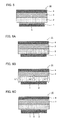
- FIGS. 3A to 3C and FIGS. 4A to 4C are outline cross-sectional diagrams illustrating the solid state lithium secondary battery of the first embodiment.
- the battery case 6 in FIGS. 3A to 3C and FIGS. 4A to 4C is intended to have been appropriately subjected to an insulating treatment so as to prevent short circuits.
- terminals are not particularly shown in the diagram, but electricity may be extracted by any arbitrary method.
- a short circuit preventing region 11 configured to include an inert gas is provided around the anode current collector 1.
- a short circuit preventing region 11 constructed from an insulating material different from the solid electrolyte layer 2 is provided around the anode current collector 1.
- the insulating material any material which does not have electron conduction can be used.
- a solid electrolyte layer 2 is disposed around the anode current collector 1. In other words, the anode current collector 1 is disposed so as to be embedded in the solid electrolyte layer 2.
- a short circuit preventing region 11 formed from an insulation-treated section is provided on the surface on the side of the solid electrolyte layer 2 (position corresponding to the outer periphery of the solid electrolyte layer 2) of the anode current collector 1.
- the outer periphery of the anode current collector 1 is at the position denoted as ⁇ .
- a hollow-shaped member is used as a battery case 6. This hollow-shaped member may be the molding tool used when the solid electrolyte layer 2 is formed.
- a short circuit preventing region 11 formed from an insulating material different from the solid electrolyte layer 2 is provided around the anode current collector 1; however, the short circuit preventing region 11 may also be configured to include an inert gas as shown in FIG. 3A .
- the battery case 6 also functions as the anode current collector 1 and the cathode current collector 4. As such, the battery case may also function as at least one of the anode current collector and the cathode current collector.
- the solid state lithium secondary battery may have a charge control unit that controls the current density at the time of charging.
- the current density at the time of charging is not particularly limited as long as it is a current density at which a short circuit does not occur; however, the current density at the time of charging is, for example, 0.026 mA/cm 2 or more, preferably 0.26 mA/cm 2 or more, and more preferably 2.6 mA/cm 2 or more.
- the current density at the time of charging is, for example, 52 mA/cm 2 or less, preferably 10.4 mA/cm 2 or less, and more preferably 5.2 mA/cm 2 or less.
- the solid state lithium secondary battery may be imparted with a confining pressure in the thickness direction, by a restraint member.
- the kind of the restraint member is not particularly limited, and any general restraint member can be used.
- the confining pressure (planar pressure) is not particularly limited; however, the confining pressure is, for example, 0.1 MPa or more, and preferably 1 MPa or more. When the confining pressure is increased, it is advantageous in that the contact between particles, such as the contact between the active material particles and the electrolyte particles, can be easily maintained.
- the confining pressure (planar pressure) is, for example, 100 MPa or less, and preferably 50 MPa or less. It is because if the confining pressure is too large, the restraint member may be requested to have high rigidity, and there is a possibility that the size of the restraint member may be increased.
- the use of the solid state lithium secondary battery is not particularly limited, but the battery is useful as, for example, a battery for vehicles.
- Examples of the shape of the solid state lithium secondary battery include a coin shape, a laminate shape, a cylindrical shape, and a rectangular shape.
- FIG. 5 is an outline cross-sectional diagram illustrating an example of the solid state lithium secondary battery of the second embodiment.
- the solid state lithium secondary battery 10 of the second embodiment comprises an anode current collector 1, a solid electrolyte layer 2, a cathode active material layer 3, and a cathode current collector 4 in this order.
- the solid state lithium secondary battery comprises an anode active material layer 5 composed of precipitated Li metal on the side of the solid electrolyte layer 2 of the anode current collector 1.
- anode active material layer 5 composed of precipitated Li metal on the side of the solid electrolyte layer 2 of the anode current collector 1.
- Li metal has been precipitated on the surface of the anode current collector
- FE-SEM field emission type scanning electron microscopy
- the Li metal exists uniformly in a dense state.
- the Li metal exists in a slightly sparse state, in relative conformity with the electrolyte.
- the surface of the precipitated Li metal is occasionally in a fibrous state (diameter about 100 nm).
- the outer periphery of the anode current collector is formed inwardly of the outer periphery of the solid electrolyte layer, and the distance between the two is larger than or equal to a predetermined value, a solid state lithium secondary battery in which the occurrence of a short circuit at the time of charging is suppressed, can be obtained.
- the thickness of the Li metal precipitated on the surface of the anode current collector is not particularly limited; however, the thickness is usually sufficiently smaller than the value of the distance D. Furthermore, the thickness of the Li metal also varies depending on the state of charge.
- the maximum thickness of the Li metal is, for example, 50 ⁇ m or less, preferably 30 ⁇ m or less, and more preferably 20 ⁇ m or less. Incidentally, the maximum thickness of the Li metal calculated as an average thickness in a state in which charging has proceeded to the maximum.
- the Li metal precipitated at the time of charging is utilized as the anode active material. Therefore, the amount of Li in the entire battery is usually consistent with the amount of Li of the cathode active material layer and the solid electrolyte layer. Furthermore, in a case where an electrochemical oxidation-reduction decomposition reaction or the like does not occur in the solid electrolyte layer, since the amount of Li of the solid electrolyte layer is constant, the amount of Li decreased from the cathode active material layer at the time of charging is consistent with the amount of Li precipitated on the anode current collector at the time of charging. Furthermore, there are occasions in which when charging has been achieved completely, the cathode active material does not contain Li.
- the solid state lithium secondary battery of the second embodiment corresponds to a state in which the solid state lithium secondary battery of the first embodiment has been subjected to charging.
- FIGS. 6A to 6C are outline cross-sectional diagrams illustrating an example of the method for producing a solid state lithium secondary battery of the invention.
- a laminate 11 including an anode current collector 1, a solid electrolyte layer 2, a cathode active material layer 3, and a cathode current collector 4 in this order is prepared ( FIG. 6A ).
- the solid electrolyte layer 2 is disposed on the surface of the anode current collector 1, and the two are in contact.
- the laminate 11 is produced, at least the solid electrolyte layer 2 is formed by a pressurization treatment.
- the laminate 11 is subjected to a charging treatment, and thus Li contained in the cathode active material layer 3 is caused to migrate toward the anode current collector 1 side ( FIG. 6B ). Thereby, Li metal (anode active material layer 5) is precipitated on the surface of the anode current collector 1 ( FIG. 6C ).
- Li metal anode active material layer 5
- the outer periphery of the anode current collector is formed inwardly of the outer periphery of the solid electrolyte layer, and the distance between the two is larger than or equal to a predetermined value, a solid state lithium secondary battery in which the occurrence of a short circuit at the time of charging is suppressed, can be obtained.
- the preparation step according to the present invention is a step of preparing a laminate including an anode current collector, a solid electrolyte layer, a cathode active material layer, and a cathode current collector in this order.
- the matters are the same as the matters described in the above section "A. Solid state lithium secondary battery", and therefore, further description will not be repeated herein.
- the method for producing a laminate is not particularly limited as long as the method is a method of forming at least a solid electrolyte layer by a pressurization treatment. Through the pressurization treatment described above, plastic deformation of the sulfide solid electrolyte particles usually occurs. Furthermore, when the solid electrolyte layer is formed, it is preferable to use a molding tool (for example, a mold).
- a solid electrolyte layer by introducing a material for forming a solid electrolyte layer including sulfide solid electrolyte particles into a molding tool, and performing a pressurization treatment using a pressurizing tool.
- the material for forming a solid electrolyte layer may be in a powder form, or may be in a layered form.
- the layered material for forming a solid electrolyte layer can be obtained by, for example, applying a material for forming a solid electrolyte layer in a slurry form on a substrate, and then drying the slurry.
- An anode current collector may be disposed on the surface from which the substrate has been detached.
- the molding tool may be in a hollow shape, or may have depressions. Furthermore, the molding tool may be used as the battery case.
- the maximum pressure applied to the solid electrolyte layer is, for example, 550 MPa or more, and is preferably 600 MPa or more, more preferably 650 MPa or more, even more preferably 700 MPa or more, and particularly preferably 750 MPa or more.
- the maximum pressure applied to the solid electrolyte layer is, for example, 1000 MPa or less, and preferably 800 MPa or less. If the pressure applied to the solid electrolyte layer is too large, there is a possibility that the size of the tool may be enlarged, or a defect such as a decrease in the battery performance caused by cracking in the solid electrolyte particles.
- the "maximum pressure applied to the solid electrolyte layer” denotes the highest pressure among the pressures applied in the step of producing a laminate, as well as the pressures applied to the solid electrolyte layer in the steps described below.
- the method of applying pressure in the invention is not particularly limited; however, examples thereof include flat plate pressing and roll pressing.
- any method can be employed as the method for producing the laminate.
- the material for forming a solid electrolyte layer may be subjected to a pressurization treatment, or the material for forming a solid electrolyte layer may be subjected to a pressurization treatment together with a portion or all of the materials for forming other members.
- the number of pressurization treatments carried out during the production of the laminate may be once, or may be several times.
- the charging step according to the present invention is a step of subjecting the laminate to a charging treatment.
- the current density at the time of charging is not particularly limited as long as it is a current density at which short circuits do not occur; however, the current density is, for example, 0.026 mA/cm 2 or more, preferably 0.26 mA/cm 2 or more, and more preferably 2.6 mA/cm 2 or more.
- the current density at the time of charging is, for example, 52 mA/cm 2 or less, and is preferably 10.4 mA/cm 2 or less, and more preferably 5.2 mA/cm 2 or less.
- a confining pressure may be, or may not be, applied to the laminate at the time of charging.
- the confining pressure is, for example, 0.1 MPa or more, and is preferably 1 MPa or more.
- the confining pressure is, for example, 100 MPa or less, and is preferably 50 MPa or less. This is because if the confining pressure is too large, the restraint member may be requested to have high rigidity, and there is a possibility that the size of the restraint member may be enlarged.
- Solid state lithium secondary battery obtainable by the present invention, the same matters as those of the above section "A. Solid state lithium secondary battery, 2. Second embodiment” apply, and therefore, further description will not be repeated herein.
- the present invention is not intended to be limited to the embodiments described above.
- the embodiments described above are only for illustrative purposes, and any embodiment that has substantially the same configuration as the technical ideas described in the claims of the invention and provides a similar operating effect is included in the technical scope of the present invention.
- Li 2 S Lithium sulfide
- P 2 S 5 diphosphorus pentasulfide
- LiI lithium iodide
- a coating layer composed of LiNbO 3 (average thickness 10 nm) was formed on the surface of the cathode active material using a tumbling flow coating apparatus (manufactured by Powrex Corp., MP01TM).
- the cathode active material thus obtained LiCoO 2 coated with LiNbO 3
- PVdF binder
- the slurry for cathode was applied on a carbon-coated aluminum (Al) foil (cathode current collector) with a doctor blade.
- the slurry for cathode was subjected to natural drying, followed by drying under the conditions of 100°C for 1 hour, and thus a cathode was obtained.
- the cathode active material, the solid electrolyte layer, and the anode current collector were disposed concentrically as illustrated in FIG. 1B .
- the weight of the cathode active material layer was 21.5 mg
- the weight of the solid electrolyte layer was 3.2 mg
- the thickness of the solid electrolyte layer was 15 ⁇ m.
- a battery for evaluation was obtained in the same manner as in Example 1, except that a piston having a diameter of 11.28 mm was used as the anode current collector.
- a battery for evaluation was obtained in the same manner as in Comparative Example 1, except that the weight of the solid electrolyte layer was adjusted to 10.7 mg, and the thickness of the solid electrolyte layer was adjusted to 50 ⁇ m.
- Charge-discharge measurement was carried out using the batteries for evaluation obtained in Example 1 and Comparative Examples 1 and 2.
- the measurement conditions were set to 25°C, a potential range of 3.0 V to 4.2 V, a current density of 0.26 mA/cm 2 , and constant current (CC) charge-discharge.
- CC constant current
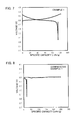
- Example 1 clear signs of an internal short circuit were not seen during charging, and charging up to 4.2 V was enabled. Furthermore, discharging up to 3.0 V was enabled. In contrast, in Comparative Example 1, a rapid decrease in voltage during charging was confirmed, and charging could not be achieved up to 4.2 V. Furthermore, the charging capacity became larger than 137 mAh/g, the theoretical capacity of LiCoO 2 . This is speculated to be because an internal short circuit occurred, and an increase in voltage caused by charging was not normally achieved. Furthermore, the discharging capacity was also small.
- Example 1 The results for the coulombic efficiency are presented in FIG. 10 .
- a coulombic efficiency as high as 93% was obtained, and it was confirmed that an internal short circuit did not occur.
- Example 1 slight irreversibility was confirmed; however, this is speculated to be because a chemical reaction between the sulfide solid electrolyte particles and Li metal occurred, or because the battery lacked Li metal from an electrical viewpoint.
- Comparative Example 1 a very low coulombic efficiency of 8% was obtained.
- charging was terminated in 20 hours; however, if charging was carried out for 20 hours or longer, the coulombic efficiency would further be decreased.
- Comparative Example 2 a low coulombic efficiency of 51% was obtained. It is speculated that in Comparative Examples 1 and 2, an internal short circuit occurred during charging, as described above.
- FIG. 11 the outer periphery of the solid electrolyte layer was peeled at a width of about 250 ⁇ m, and the cathode active material layer was exposed. Inferring from the mechanism, it is speculated that dendrites are generated in an area where the cathode active material layer is exposed (area where the solid electrolyte layer has been peeled off), or a bright area seen at the interface between the solid electrolyte layer and the cathode active material (area with many voids). As illustrated in FIG.
- the distance of the area where the cathode active material layer is exposed is about 250 ⁇ m, and the distance including the area having many voids is about 300 ⁇ m. Therefore, when the distance D between the outer periphery of the solid electrolyte layer and the outer periphery of the anode current collector is 300 ⁇ m or more, the effect of the present invention is obtained. Furthermore, it was confirmed that with regard to the outer periphery of the solid electrolyte, in a case where the thickness of the solid electrolyte layer is small, a large number of voids are generated in the outer periphery and cause the generation of dendrites.
Landscapes
- Chemical & Material Sciences (AREA)
- Engineering & Computer Science (AREA)
- General Chemical & Material Sciences (AREA)
- Chemical Kinetics & Catalysis (AREA)
- Electrochemistry (AREA)
- Manufacturing & Machinery (AREA)
- Materials Engineering (AREA)
- Physics & Mathematics (AREA)
- Condensed Matter Physics & Semiconductors (AREA)
- General Physics & Mathematics (AREA)
- Inorganic Chemistry (AREA)
- Secondary Cells (AREA)
- Battery Electrode And Active Subsutance (AREA)
Applications Claiming Priority (1)
| Application Number | Priority Date | Filing Date | Title |
|---|---|---|---|
| JP2014134125A JP2016012495A (ja) | 2014-06-30 | 2014-06-30 | リチウム固体二次電池およびその製造方法 |
Publications (1)
| Publication Number | Publication Date |
|---|---|
| EP2963704A1 true EP2963704A1 (fr) | 2016-01-06 |
Family
ID=53719611
Family Applications (1)
| Application Number | Title | Priority Date | Filing Date |
|---|---|---|---|
| EP15174022.2A Withdrawn EP2963704A1 (fr) | 2014-06-30 | 2015-06-26 | Batterie secondaire au lithium à l'état solide et son procedé de fabrication |
Country Status (5)
| Country | Link |
|---|---|
| US (1) | US20150380763A1 (fr) |
| EP (1) | EP2963704A1 (fr) |
| JP (1) | JP2016012495A (fr) |
| KR (1) | KR20160002364A (fr) |
| CN (1) | CN105226319A (fr) |
Cited By (1)
| Publication number | Priority date | Publication date | Assignee | Title |
|---|---|---|---|---|
| EP3509139A4 (fr) * | 2016-08-30 | 2019-08-28 | FUJIFILM Corporation | Composition d'électrolyte solide, feuille contenant un électrolyte solide, batterie secondaire entièrement solide, procédé de production d'une feuille contenant un électrolyte solide, et procédé de production d'une batterie secondaire entièrement solide |
Families Citing this family (34)
| Publication number | Priority date | Publication date | Assignee | Title |
|---|---|---|---|---|
| JP6563364B2 (ja) * | 2016-05-31 | 2019-08-21 | 株式会社三五 | 二次電池用負極 |
| US10818976B2 (en) * | 2016-06-29 | 2020-10-27 | International Business Machines Corporation | Rechargeable battery |
| JP6934727B2 (ja) * | 2017-01-31 | 2021-09-15 | 日立造船株式会社 | 全固体電池およびその製造方法 |
| KR102093971B1 (ko) * | 2017-06-21 | 2020-05-21 | 주식회사 엘지화학 | 리튬 이차전지 |
| JP6943656B2 (ja) * | 2017-07-12 | 2021-10-06 | 日立造船株式会社 | コイン形電池およびその製造方法 |
| CN109390622B (zh) * | 2017-08-10 | 2022-03-22 | 丰田自动车株式会社 | 锂固体电池 |
| JP6926972B2 (ja) * | 2017-11-10 | 2021-08-25 | トヨタ自動車株式会社 | 全固体電池の製造方法 |
| KR102773012B1 (ko) * | 2018-01-09 | 2025-02-25 | 더 리젠츠 오브 더 유니버시티 오브 미시건 | 리튬 이온 전도성 고체 전해질로 클래딩된 집전체 |
| JP7035643B2 (ja) * | 2018-03-09 | 2022-03-15 | 富士通株式会社 | リチウム二次電池 |
| WO2019187915A1 (fr) * | 2018-03-28 | 2019-10-03 | 日本碍子株式会社 | Batterie secondaire au lithium et carte ayant une batterie intégrée |
| JP6905148B2 (ja) * | 2018-03-28 | 2021-07-21 | 日本碍子株式会社 | リチウム二次電池及び電池内蔵カード |
| JP2019200851A (ja) * | 2018-05-14 | 2019-11-21 | トヨタ自動車株式会社 | 固体電解質、全固体電池および固体電解質の製造方法 |
| CN108550859B (zh) * | 2018-05-21 | 2021-04-06 | 珠海冠宇电池股份有限公司 | 多孔集流体及其制备方法和锂电池 |
| JP7133132B2 (ja) * | 2018-07-06 | 2022-09-08 | トヨタ自動車株式会社 | 全固体電池組立体の短絡検査方法およびこれに用いる拘束治具と短絡検査用のキット、ならびに全固体電池の製造方法 |
| US12080880B2 (en) * | 2018-09-25 | 2024-09-03 | Toyota Motor Engineering & Manufacturing North America, Inc. | Nano-alloy interphase for lithium metal solid state batteries |
| CN109824023B (zh) * | 2019-01-25 | 2021-04-09 | 广州汉源新材料股份有限公司 | 一种Li-Sn基合金固体电解质及其制备方法 |
| JP7274300B2 (ja) * | 2019-02-14 | 2023-05-16 | 日産自動車株式会社 | 全固体電池 |
| KR102501561B1 (ko) * | 2019-03-22 | 2023-02-20 | 후지필름 가부시키가이샤 | 전고체 리튬 이온 이차 전지와 그 제조 방법, 및 부극용 적층 시트 |
| JP7366574B2 (ja) * | 2019-04-10 | 2023-10-23 | 本田技研工業株式会社 | 固体電解質シート、全固体電池、セパレータ及びリチウムイオン電池 |
| KR102754480B1 (ko) * | 2019-05-08 | 2025-01-17 | 주식회사 엘지에너지솔루션 | 전고체전지의 제조방법 및 이를 이용하여 제조되는 전고체전지 |
| KR20210111949A (ko) * | 2020-03-03 | 2021-09-14 | 삼성에스디아이 주식회사 | 양극 및 이를 포함하는 전고체 이차전지, 및 전고체 이차전지의 제조 방법 |
| JP7368320B2 (ja) * | 2020-06-09 | 2023-10-24 | トヨタ自動車株式会社 | バインダ組成物、バインダ組成物の製造方法、および全固体電池の製造方法 |
| KR102634217B1 (ko) | 2020-09-23 | 2024-02-07 | 도요타 지도샤(주) | 전고체 전지의 제조 방법 |
| JP7784230B2 (ja) * | 2021-01-13 | 2025-12-11 | 日産自動車株式会社 | 全固体電池 |
| JP7624322B2 (ja) * | 2021-02-16 | 2025-01-30 | マクセル株式会社 | 全固体二次電池およびその製造方法 |
| JP7725211B2 (ja) * | 2021-02-16 | 2025-08-19 | マクセル株式会社 | 全固体二次電池及びその製造方法 |
| US20240154182A1 (en) * | 2021-03-29 | 2024-05-09 | Nissan Motor Co., Ltd. | Lithium Secondary Battery |
| KR102806854B1 (ko) * | 2021-03-30 | 2025-05-14 | 주식회사 엘지에너지솔루션 | 다공성 집전체를 포함하는 전고체전지 및 이를 포함하는 전지모듈 |
| JP7780932B2 (ja) * | 2021-12-10 | 2025-12-05 | 日産自動車株式会社 | 全固体リチウム二次電池の製造方法 |
| JP7828166B2 (ja) * | 2021-12-16 | 2026-03-11 | 日産自動車株式会社 | 全固体電池 |
| JP7548261B2 (ja) * | 2022-03-18 | 2024-09-10 | トヨタ自動車株式会社 | 二次電池 |
| JP2023148244A (ja) * | 2022-03-30 | 2023-10-13 | 本田技研工業株式会社 | 固体電池 |
| JP2025037080A (ja) * | 2023-09-05 | 2025-03-17 | トヨタ自動車株式会社 | 全固体電池および全固体電池の製造方法 |
| WO2025243375A1 (fr) * | 2024-05-20 | 2025-11-27 | 日産自動車株式会社 | Batterie tout solide |
Citations (6)
| Publication number | Priority date | Publication date | Assignee | Title |
|---|---|---|---|---|
| JPH07312226A (ja) | 1994-05-16 | 1995-11-28 | Yuasa Corp | 有機固体電解質電池 |
| US6168884B1 (en) * | 1999-04-02 | 2001-01-02 | Lockheed Martin Energy Research Corporation | Battery with an in-situ activation plated lithium anode |
| JP2011044368A (ja) | 2009-08-24 | 2011-03-03 | Sumitomo Electric Ind Ltd | 非水電解質電池 |
| JP2011159596A (ja) | 2010-02-03 | 2011-08-18 | Sumitomo Electric Ind Ltd | 二次電池、及びその製造方法 |
| JP2012099289A (ja) * | 2010-10-29 | 2012-05-24 | Sumitomo Electric Ind Ltd | 非水電解質電池 |
| JP2013093241A (ja) * | 2011-10-26 | 2013-05-16 | Sumitomo Electric Ind Ltd | 非水電解質電池、及び非水電解質電池の製造方法 |
Family Cites Families (4)
| Publication number | Priority date | Publication date | Assignee | Title |
|---|---|---|---|---|
| JP2008288037A (ja) * | 2007-05-17 | 2008-11-27 | Toyota Motor Corp | 全固体リチウム二次電池の製造方法 |
| JP2009266589A (ja) * | 2008-04-24 | 2009-11-12 | Toyota Motor Corp | 固体リチウム二次電池およびその製造方法 |
| JP2011159467A (ja) * | 2010-01-29 | 2011-08-18 | Sumitomo Electric Ind Ltd | 非水電解質電池 |
| JP2012146553A (ja) * | 2011-01-13 | 2012-08-02 | Idemitsu Kosan Co Ltd | リチウムイオン電池負極部材及び負極 |
-
2014
- 2014-06-30 JP JP2014134125A patent/JP2016012495A/ja active Pending
-
2015
- 2015-06-23 KR KR1020150088935A patent/KR20160002364A/ko not_active Ceased
- 2015-06-25 CN CN201510359013.2A patent/CN105226319A/zh active Pending
- 2015-06-26 EP EP15174022.2A patent/EP2963704A1/fr not_active Withdrawn
- 2015-06-29 US US14/753,784 patent/US20150380763A1/en not_active Abandoned
Patent Citations (6)
| Publication number | Priority date | Publication date | Assignee | Title |
|---|---|---|---|---|
| JPH07312226A (ja) | 1994-05-16 | 1995-11-28 | Yuasa Corp | 有機固体電解質電池 |
| US6168884B1 (en) * | 1999-04-02 | 2001-01-02 | Lockheed Martin Energy Research Corporation | Battery with an in-situ activation plated lithium anode |
| JP2011044368A (ja) | 2009-08-24 | 2011-03-03 | Sumitomo Electric Ind Ltd | 非水電解質電池 |
| JP2011159596A (ja) | 2010-02-03 | 2011-08-18 | Sumitomo Electric Ind Ltd | 二次電池、及びその製造方法 |
| JP2012099289A (ja) * | 2010-10-29 | 2012-05-24 | Sumitomo Electric Ind Ltd | 非水電解質電池 |
| JP2013093241A (ja) * | 2011-10-26 | 2013-05-16 | Sumitomo Electric Ind Ltd | 非水電解質電池、及び非水電解質電池の製造方法 |
Non-Patent Citations (4)
| Title |
|---|
| B J NEUDECKER ET AL: ""Lithium-Free" Thin-Film Battery with In Situ Plated Li Anode", JOURNAL OF THE ELECTROCHEMICAL SOCIETY, vol. 147, no. 2, 1 February 2000 (2000-02-01), pages 517 - 523, XP055208024 * |
| MITSUYASU OGAWA ET AL: "High-capacity thin film lithium batteries with sulfide solid electrolytes", JOURNAL OF POWER SOURCES, vol. 205, 21 January 2012 (2012-01-21), pages 487 - 490, XP055208221, ISSN: 0378-7753, DOI: 10.1016/j.jpowsour.2012.01.086 * |
| MOTOHIRO NAGAO ET AL: "In situ SEM study of a lithium deposition and dissolution mechanism in a bulk-type solid-state cell with a Li2S-P2S5 solid electrolyte", PHYSICAL CHEMISTRY CHEMICAL PHYSICS, vol. 15, no. 42, 1 January 2013 (2013-01-01), pages 18600, XP055208026, ISSN: 1463-9076, DOI: 10.1039/c3cp51059j * |
| ZHE LI ET AL: "A review of lithium deposition in lithium-ion and lithium metal secondary batteries", JOURNAL OF POWER SOURCES, vol. 254, 4 January 2014 (2014-01-04), pages 168 - 182, XP055208104, ISSN: 0378-7753, DOI: 10.1016/j.jpowsour.2013.12.099 * |
Cited By (1)
| Publication number | Priority date | Publication date | Assignee | Title |
|---|---|---|---|---|
| EP3509139A4 (fr) * | 2016-08-30 | 2019-08-28 | FUJIFILM Corporation | Composition d'électrolyte solide, feuille contenant un électrolyte solide, batterie secondaire entièrement solide, procédé de production d'une feuille contenant un électrolyte solide, et procédé de production d'une batterie secondaire entièrement solide |
Also Published As
| Publication number | Publication date |
|---|---|
| CN105226319A (zh) | 2016-01-06 |
| US20150380763A1 (en) | 2015-12-31 |
| JP2016012495A (ja) | 2016-01-21 |
| KR20160002364A (ko) | 2016-01-07 |
Similar Documents
| Publication | Publication Date | Title |
|---|---|---|
| EP2963704A1 (fr) | Batterie secondaire au lithium à l'état solide et son procedé de fabrication | |
| US9954248B2 (en) | Solid lithium secondary battery and method of manufacturing same | |
| CN104868164B (zh) | 制造固态锂电池模块的方法 | |
| JP6090249B2 (ja) | 複合活物質及びその製造方法 | |
| US9337509B2 (en) | Solid electrolyte material, solid state battery, and method for producing solid electrolyte material | |
| EP2954575B1 (fr) | Matériau actif composite, procédé de fabrication du matériau actif composite, et batterie secondaire au lithium comprenant le matériau actif composite | |
| EP3089254B1 (fr) | Batterie au lithium à électrolyte solide, module de batteries au lithium à électrolyte solide, et procédé de production d'une batterie au lithium à électrolyte solide | |
| JP5177315B2 (ja) | 硫化物系固体電池 | |
| US20140287324A1 (en) | Electrolyte-coated cathode active material particles, all solid state battery, and method for producing electrolyte-coated cathode active material particles | |
| CN112635763A (zh) | 全固体电池 | |
| JP2013222530A (ja) | 全固体電池及び全固体電池の充放電方法 | |
| KR20160081582A (ko) | 복합 음극 활물질, 그 제조방법, 이를 포함하는 음극 및 리튬이차전지 | |
| CN114242942A (zh) | 一种具有稳定负极界面的复合缓冲层及其固态锂金属电池 | |
| TW202103358A (zh) | 複合粒子及鋰離子二次電池用負極材料 | |
| JP6927131B2 (ja) | 全固体電池の製造方法、全固体電池および全固体電池システム | |
| CN112563477A (zh) | 负极材料及其制造方法 | |
| EP4158714A1 (fr) | Nouveaux électrolytes à base de sulfure solide | |
| EP4636847A1 (fr) | Matériau actif de cathode pour batterie secondaire au lithium, batterie secondaire au lithium le comprenant, et procédé de préparation de matériau actif de cathode pour batterie secondaire au lithium | |
| CN111180739A (zh) | 负极 | |
| 安部勇輔 | Charging and Discharging Performances of Advanced Li-ion Batteries Using Eco-friendly Active Materials |
Legal Events
| Date | Code | Title | Description |
|---|---|---|---|
| PUAI | Public reference made under article 153(3) epc to a published international application that has entered the european phase |
Free format text: ORIGINAL CODE: 0009012 |
|
| 17P | Request for examination filed |
Effective date: 20150626 |
|
| AK | Designated contracting states |
Kind code of ref document: A1 Designated state(s): AL AT BE BG CH CY CZ DE DK EE ES FI FR GB GR HR HU IE IS IT LI LT LU LV MC MK MT NL NO PL PT RO RS SE SI SK SM TR |
|
| AX | Request for extension of the european patent |
Extension state: BA ME |
|
| STAA | Information on the status of an ep patent application or granted ep patent |
Free format text: STATUS: THE APPLICATION IS DEEMED TO BE WITHDRAWN |
|
| 18D | Application deemed to be withdrawn |
Effective date: 20160707 |