EP2964978B1 - Hydraulic system for a dual-clutch transmission - Google Patents
Hydraulic system for a dual-clutch transmission Download PDFInfo
- Publication number
- EP2964978B1 EP2964978B1 EP14707653.3A EP14707653A EP2964978B1 EP 2964978 B1 EP2964978 B1 EP 2964978B1 EP 14707653 A EP14707653 A EP 14707653A EP 2964978 B1 EP2964978 B1 EP 2964978B1
- Authority
- EP
- European Patent Office
- Prior art keywords
- pressure
- clutch
- accumulator
- dual
- hydraulic
- Prior art date
- Legal status (The legal status is an assumption and is not a legal conclusion. Google has not performed a legal analysis and makes no representation as to the accuracy of the status listed.)
- Not-in-force
Links
Images

Classifications
-
- F—MECHANICAL ENGINEERING; LIGHTING; HEATING; WEAPONS; BLASTING
- F16—ENGINEERING ELEMENTS AND UNITS; GENERAL MEASURES FOR PRODUCING AND MAINTAINING EFFECTIVE FUNCTIONING OF MACHINES OR INSTALLATIONS; THERMAL INSULATION IN GENERAL
- F16H—GEARING
- F16H61/00—Control functions within control units of change-speed- or reversing-gearings for conveying rotary motion ; Control of exclusively fluid gearing, friction gearing, gearings with endless flexible members or other particular types of gearing
- F16H61/0021—Generation or control of line pressure
- F16H61/0025—Supply of control fluid; Pumps therefor
-
- F—MECHANICAL ENGINEERING; LIGHTING; HEATING; WEAPONS; BLASTING
- F16—ENGINEERING ELEMENTS AND UNITS; GENERAL MEASURES FOR PRODUCING AND MAINTAINING EFFECTIVE FUNCTIONING OF MACHINES OR INSTALLATIONS; THERMAL INSULATION IN GENERAL
- F16D—COUPLINGS FOR TRANSMITTING ROTATION; CLUTCHES; BRAKES
- F16D48/00—External control of clutches
- F16D48/06—Control by electric or electronic means, e.g. of fluid pressure
- F16D48/062—Control by electric or electronic means, e.g. of fluid pressure of a clutch system with a plurality of fluid actuated clutches
-
- F—MECHANICAL ENGINEERING; LIGHTING; HEATING; WEAPONS; BLASTING
- F16—ENGINEERING ELEMENTS AND UNITS; GENERAL MEASURES FOR PRODUCING AND MAINTAINING EFFECTIVE FUNCTIONING OF MACHINES OR INSTALLATIONS; THERMAL INSULATION IN GENERAL
- F16D—COUPLINGS FOR TRANSMITTING ROTATION; CLUTCHES; BRAKES
- F16D48/00—External control of clutches
- F16D48/06—Control by electric or electronic means, e.g. of fluid pressure
- F16D48/066—Control of fluid pressure, e.g. using an accumulator
-
- F—MECHANICAL ENGINEERING; LIGHTING; HEATING; WEAPONS; BLASTING
- F16—ENGINEERING ELEMENTS AND UNITS; GENERAL MEASURES FOR PRODUCING AND MAINTAINING EFFECTIVE FUNCTIONING OF MACHINES OR INSTALLATIONS; THERMAL INSULATION IN GENERAL
- F16H—GEARING
- F16H61/00—Control functions within control units of change-speed- or reversing-gearings for conveying rotary motion ; Control of exclusively fluid gearing, friction gearing, gearings with endless flexible members or other particular types of gearing
- F16H61/68—Control functions within control units of change-speed- or reversing-gearings for conveying rotary motion ; Control of exclusively fluid gearing, friction gearing, gearings with endless flexible members or other particular types of gearing specially adapted for stepped gearings
- F16H61/684—Control functions within control units of change-speed- or reversing-gearings for conveying rotary motion ; Control of exclusively fluid gearing, friction gearing, gearings with endless flexible members or other particular types of gearing specially adapted for stepped gearings without interruption of drive
- F16H61/688—Control functions within control units of change-speed- or reversing-gearings for conveying rotary motion ; Control of exclusively fluid gearing, friction gearing, gearings with endless flexible members or other particular types of gearing specially adapted for stepped gearings without interruption of drive with two inputs, e.g. selection of one of two torque-flow paths by clutches
-
- F—MECHANICAL ENGINEERING; LIGHTING; HEATING; WEAPONS; BLASTING
- F16—ENGINEERING ELEMENTS AND UNITS; GENERAL MEASURES FOR PRODUCING AND MAINTAINING EFFECTIVE FUNCTIONING OF MACHINES OR INSTALLATIONS; THERMAL INSULATION IN GENERAL
- F16D—COUPLINGS FOR TRANSMITTING ROTATION; CLUTCHES; BRAKES
- F16D48/00—External control of clutches
- F16D48/02—Control by fluid pressure
- F16D2048/0203—Control by fluid pressure with an accumulator; Details thereof
-
- F—MECHANICAL ENGINEERING; LIGHTING; HEATING; WEAPONS; BLASTING
- F16—ENGINEERING ELEMENTS AND UNITS; GENERAL MEASURES FOR PRODUCING AND MAINTAINING EFFECTIVE FUNCTIONING OF MACHINES OR INSTALLATIONS; THERMAL INSULATION IN GENERAL
- F16D—COUPLINGS FOR TRANSMITTING ROTATION; CLUTCHES; BRAKES
- F16D48/00—External control of clutches
- F16D48/02—Control by fluid pressure
- F16D2048/0257—Hydraulic circuit layouts, i.e. details of hydraulic circuit elements or the arrangement thereof
- F16D2048/0281—Complex circuits with more than two valves in series or special arrangements thereof not provided for in previous groups
-
- F—MECHANICAL ENGINEERING; LIGHTING; HEATING; WEAPONS; BLASTING
- F16—ENGINEERING ELEMENTS AND UNITS; GENERAL MEASURES FOR PRODUCING AND MAINTAINING EFFECTIVE FUNCTIONING OF MACHINES OR INSTALLATIONS; THERMAL INSULATION IN GENERAL
- F16D—COUPLINGS FOR TRANSMITTING ROTATION; CLUTCHES; BRAKES
- F16D48/00—External control of clutches
- F16D48/02—Control by fluid pressure
- F16D2048/0257—Hydraulic circuit layouts, i.e. details of hydraulic circuit elements or the arrangement thereof
- F16D2048/0287—Hydraulic circuits combining clutch actuation and other hydraulic systems
- F16D2048/0293—Hydraulic circuits combining clutch and transmission actuation
-
- F—MECHANICAL ENGINEERING; LIGHTING; HEATING; WEAPONS; BLASTING
- F16—ENGINEERING ELEMENTS AND UNITS; GENERAL MEASURES FOR PRODUCING AND MAINTAINING EFFECTIVE FUNCTIONING OF MACHINES OR INSTALLATIONS; THERMAL INSULATION IN GENERAL
- F16D—COUPLINGS FOR TRANSMITTING ROTATION; CLUTCHES; BRAKES
- F16D2500/00—External control of clutches by electric or electronic means
- F16D2500/10—System to be controlled
- F16D2500/102—Actuator
- F16D2500/1021—Electrical type
- F16D2500/1023—Electric motor
- F16D2500/1024—Electric motor combined with hydraulic actuation
-
- F—MECHANICAL ENGINEERING; LIGHTING; HEATING; WEAPONS; BLASTING
- F16—ENGINEERING ELEMENTS AND UNITS; GENERAL MEASURES FOR PRODUCING AND MAINTAINING EFFECTIVE FUNCTIONING OF MACHINES OR INSTALLATIONS; THERMAL INSULATION IN GENERAL
- F16D—COUPLINGS FOR TRANSMITTING ROTATION; CLUTCHES; BRAKES
- F16D2500/00—External control of clutches by electric or electronic means
- F16D2500/30—Signal inputs
- F16D2500/302—Signal inputs from the actuator
- F16D2500/3024—Pressure
-
- F—MECHANICAL ENGINEERING; LIGHTING; HEATING; WEAPONS; BLASTING
- F16—ENGINEERING ELEMENTS AND UNITS; GENERAL MEASURES FOR PRODUCING AND MAINTAINING EFFECTIVE FUNCTIONING OF MACHINES OR INSTALLATIONS; THERMAL INSULATION IN GENERAL
- F16D—COUPLINGS FOR TRANSMITTING ROTATION; CLUTCHES; BRAKES
- F16D2500/00—External control of clutches by electric or electronic means
- F16D2500/30—Signal inputs
- F16D2500/31—Signal inputs from the vehicle
- F16D2500/3108—Vehicle speed
- F16D2500/3111—Standing still, i.e. signal detecting when the vehicle is standing still or bellow a certain limit speed
-
- F—MECHANICAL ENGINEERING; LIGHTING; HEATING; WEAPONS; BLASTING
- F16—ENGINEERING ELEMENTS AND UNITS; GENERAL MEASURES FOR PRODUCING AND MAINTAINING EFFECTIVE FUNCTIONING OF MACHINES OR INSTALLATIONS; THERMAL INSULATION IN GENERAL
- F16D—COUPLINGS FOR TRANSMITTING ROTATION; CLUTCHES; BRAKES
- F16D2500/00—External control of clutches by electric or electronic means
- F16D2500/30—Signal inputs
- F16D2500/314—Signal inputs from the user
- F16D2500/3148—Detection of user presence
-
- F—MECHANICAL ENGINEERING; LIGHTING; HEATING; WEAPONS; BLASTING
- F16—ENGINEERING ELEMENTS AND UNITS; GENERAL MEASURES FOR PRODUCING AND MAINTAINING EFFECTIVE FUNCTIONING OF MACHINES OR INSTALLATIONS; THERMAL INSULATION IN GENERAL
- F16D—COUPLINGS FOR TRANSMITTING ROTATION; CLUTCHES; BRAKES
- F16D2500/00—External control of clutches by electric or electronic means
- F16D2500/70—Details about the implementation of the control system
- F16D2500/704—Output parameters from the control unit; Target parameters to be controlled
- F16D2500/70402—Actuator parameters
- F16D2500/70406—Pressure
-
- F—MECHANICAL ENGINEERING; LIGHTING; HEATING; WEAPONS; BLASTING
- F16—ENGINEERING ELEMENTS AND UNITS; GENERAL MEASURES FOR PRODUCING AND MAINTAINING EFFECTIVE FUNCTIONING OF MACHINES OR INSTALLATIONS; THERMAL INSULATION IN GENERAL
- F16H—GEARING
- F16H61/00—Control functions within control units of change-speed- or reversing-gearings for conveying rotary motion ; Control of exclusively fluid gearing, friction gearing, gearings with endless flexible members or other particular types of gearing
- F16H61/0021—Generation or control of line pressure
- F16H61/0025—Supply of control fluid; Pumps therefor
- F16H2061/0034—Accumulators for fluid pressure supply; Control thereof
Definitions
- the invention relates to a dual-clutch transmission for a vehicle and to a method for carrying out a pressure-reducing mode in such a hydraulic system.
- a dual-clutch transmission according to the preamble of claim 1 is made US2012 / 144946A known.
- the clutches and the switching elements for engaging the gears are usually hydraulically controlled.
- the required hydraulic system works while driving at a storage pressure, for example, in the order of 30 bar, which is provided by a pressure accumulator of the hydraulic system.
- a control unit electrically controllable control valves. With the aid of the control valves, the hydraulic pressure applied to the first clutch and the second clutch can be adjusted.
- the control unit is also associated with first and second pressure sensors which respectively monitor the hydraulic pressure applied to the first clutch and to the second clutch. For example, if the detected pressure sensor signals do not correspond to the operating state of the first / second clutch, the control unit can detect a malfunction of the dual-clutch transmission.
- the pressure accumulator of the hydraulic system can be completely emptied when detecting longer vehicle stance phases, but this does not make energy sense.
- the accumulator pressure can be reduced to, for example, 10 bar.
- hydraulic oil deposits are prevented in the control valves.
- at least some of the pressure energy stored in the hydraulic system can nevertheless be used for the next drive during pressure build-up.
- the object of the invention is to provide a dual-clutch transmission with a hydraulic system, in which the pressure-reducing mode can be performed reliably without additional sensor-technical effort.
- the invention is based on the fact that in the known from the prior art Druckreduziermodus the control unit is a hydraulic control valve cyclically switched back and forth between the open and closed position with a predetermined number of actuating movements, so that as a result of leakage to pressure losses and thus to a reduced accumulator pressure.
- the number of actuating movements of the hydraulic control valve is chosen so that in any case the risk of oil deposits is eliminated, but without having more accurate information about the IstSpeicherbuch.
- the control unit is integrated in the pressure reduction mode in a control loop in which the first pressure sensor detecting the hydraulic pressure applied to the first clutch takes over the accumulator pressure actual value detection.
- the accumulator pressure actual value detection is thus carried out by the pressure sensor required anyway for safety reasons.
- An additional pressure sensor in the region of the pressure accumulator, however, is not required in terms of component reduction.
- the control unit the first clutch associated control valve continuously or permanently in an open position. The first pressure sensor associated with the first clutch is therefore continuously exposed to the accumulator pressure during the pressure-reducing mode.
- the first pressure sensor is fluidically in the pressure line between the first control valve and the hydraulic cylinder of the first clutch.
- the second pressure sensor is fluidically in the pressure line between the second control valve and the hydraulic cylinder of the second clutch.
- the storage pressure reduction taking place in the pressure reduction mode does not require additional pressure reducing components, for example a pressure relief valve, but already existing components in double function are also used in the pressure reduction mode.
- Prefers can therefore be adjusted cyclically between its open position and its closed position to reduce the pressure of the second clutch associated control valve. In this way, as a result of hydraulic oil leakage in the adjusting movement to pressure losses and thus to the reduced accumulator pressure.
- the control unit may, in the pressure reducing mode, actuate the control valve of the second clutch by means of a suitable function, for example a trapezoidal control, in which the control valve of the second clutch is cyclically closed and opened, whereby the accumulator is slowly emptied.
- the control valve associated with the second clutch acts as an actuator of the control loop.
- control valves assigned to the gearshift elements can also be cyclically moved back and forth between the open and closed positions in order to achieve a pressure drop by hydraulic oil leakage.
- the sole use of the control valve associated with the second clutch is advantageous.
- the two, the first and the second clutch associated pressure sensors meet in normal driving a safety function in which is monitored whether the first clutch or the second clutch is depressurized or pressurized.
- pressure sensors is no additional pressure sensor for memory pressure actual value to provide for carrying out the Druckreduziermodus invention.
- the pressure lines between the pressure accumulator and the control valves of the clutches and the gear shift elements are therefore component-technically preferably free of further pressure sensors.
- the accumulator pressure specified by the accumulator pressure may be of the order of 30 bar. After the pressure reduction mode, the accumulator pressure of these 30 bar can be reduced to a range of 0 to 10 bar.
- the pressure reducing mode may be activated based on input parameters detected by the control unit. For example, the pressure reduction mode is activated when the control unit detects that the vehicle has been decommissioned and the driver has left the vehicle. Alternatively, the pressure reduction mode may be activated by factory operation of a transfer switch in the event of a longer delivery time.
- the hydraulic system of the dual clutch transmission can be divided into a clutch hydraulic circuit and a gear actuator hydraulic circuit, both of which are pressurized by the accumulator with accumulator pressure.
- the clutch hydraulic circuit the first and second clutches are hydraulically controlled.
- the gear actuator hydraulic circuit the switching elements are hydraulically controlled.
- the gear actuator hydraulic circuit is depressurized, that is shut down by appropriate positioning of the control valves.
- a block diagram of a dual-clutch transmission for a motor vehicle with four-wheel drive is shown.
- the dual-clutch transmission has seven forward gears (see circled numerals 1 to 7) and one reverse RW.
- the dual-clutch transmission is described below only insofar as it is necessary for the understanding of the invention.
- the dual-clutch transmission on two input shafts 12, 14 which are arranged coaxially with each other and via two hydraulically actuated multi-plate clutches K1 and K2 alternately with the drive source, for example, a (not shown) internal combustion engine, are connectable.
- the input shaft 14 is designed as a hollow shaft in which the solid shaft designed as input shaft 12 is guided.
- the input shafts 12, 14 drive via gear sets of the forward gears 1 to 7 and a reverse gear RW on an axially parallel output shaft 16 and an intermediate shaft formed as a hollow shaft 18.
- the gear sets of forward gears 1 to 7 each have fixed gears and switch elements 22 via switchable idler gears.
- the switching elements 22 may be exemplified double synchronizer clutches, which can each switch from a neutral position, two adjacent Losyak21.
- the third gear switching Switching element 22, however, according to the Fig. 1 a single clutch that couples only one loose gear on the intermediate shaft 18.
- the partial transmission I of the dual-clutch transmission has the gears for the odd forward gears 1, 3, 5 and 7, which are driven via the hollow input shaft 14.
- the partial transmission II, the straight forward gears 2, 4, 6 and the reverse gear RW are assigned, which can be activated via the clutch K2 and the input shaft 12, wherein the gears are connected by respective closing of the respective switching elements 22.
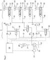
- the hydraulic system of the dual clutch transmission is shown as a simplified block diagram.
- the hydraulic cylinders 23 of the clutches K1, K2 and the switching elements 22 can be actuated.
- the hydraulic system is roughly divided into a clutch hydraulic circuit A and a gear actuator hydraulic circuit B.
- the two hydraulic circuits A, B are acted upon via a pressure accumulator 25 with the accumulator pressure p S.
- a main line 27 connected to the pressure accumulator 25 is led to a branch point 29 at which a first part line 31 to the hydraulic cylinder 23 of the first clutch K1 and a second part line 33 to the hydraulic cylinder 23 of the second clutch K2 is performed.
- a first control valve 35 and a second control valve 37 are arranged in each case, which can be controlled via a central control unit 39.
- the control unit 39 is a first pressure sensor 41 and a second pressure sensor 43 signal technology in conjunction.
- the pressure sensors 41, 43 respectively detect the hydraulic pressure applied to the first clutch K1 and to the second clutch K2.
- branching point 29 branches one, fluidly connected to the gear actuator hydraulic circuit B.
- the connecting line 45 is divided downstream of the control valve 47 in a total of four sub-lines 49, which are each guided via further control valves 51 to the hydraulic cylinders 23 of the switching elements 22.
- the hydraulic system has a pressure pump 53 which is connected on the input side to an oil sump 55.
- the pressure pump 53 can be actuated by the control unit 39 for charging the pressure accumulator via an electric motor 57.
- the hydraulic system has according to the Fig. 2 or 3 a clutch hydraulic circuit A, with which the clutches K1, K2 are hydraulically actuated, and a gear selector hydraulic circuit B, with which the gear shift elements 22 are hydraulically actuated.
- control unit 39 controls the control valves 35, 37, 47, 51 of the clutches K1, K2 and the gear shift elements 22 of the dual-clutch transmission to ensure a fully automatic gear change without interruption of traction.
- the predetermined during driving from the pressure accumulator 25 storage pressure p s may be exemplary in the order of 30 bar.
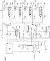
- control unit 39 can detect input parameters that indicate a longer service life of the vehicle. In this case, the control unit 39 activates a pressure reducing mode in which the accumulator pressure p s provided from the accumulator 25 is reduced.
- the pressure sensor 41 assigned to the first clutch K1 together with the control unit 39 is in a control circuit R (FIG. Fig. 3 ), in which the first pressure sensor 41 assumes the accumulator pressure actual value acquisition p actual .
- the control valve 37 of the second clutch K2 is included in the control loop R, as an actuator which is cyclically adjusted between the open and closed positions, so that it as a result of leakage during the adjusting movement to pressure losses and thus to a reduced Accumulator pressure p s comes.
- the control circuit R the accumulator pressure p S is reduced from the abovementioned 30 bar to an exemplary value of 10 bar given by the control unit 39.
- control valve 35 associated with the first clutch K1 In order for the control valve 35 associated with the first clutch K1 to be able to perform a flawless actual value detection, it is continuously in the open position in the pressure reduction mode (FIG. Fig. 3 ). Furthermore, in the pressure reduction mode, the gear actuator hydraulic circuit B is permanently depressurized, that is shut down.
Landscapes
- Engineering & Computer Science (AREA)
- General Engineering & Computer Science (AREA)
- Mechanical Engineering (AREA)
- Physics & Mathematics (AREA)
- Fluid Mechanics (AREA)
- Control Of Transmission Device (AREA)
- Hydraulic Clutches, Magnetic Clutches, Fluid Clutches, And Fluid Joints (AREA)
Description
Die Erfindung betrifft ein Doppelkupplungsgetriebe für ein Fahrzeug sowie ein Verfahren zur Durchführung eines Druckreduziermodus in einem solchen Hydrauliksystem.The invention relates to a dual-clutch transmission for a vehicle and to a method for carrying out a pressure-reducing mode in such a hydraulic system.
Ein Doppelkupplungsgetriebe gemäß dem Oberbegriff des Anspruchs 1 ist aus
Bei einem Doppelkupplungsgetriebe ist mittels zweier Teilgetriebe ein vollautomatischer Gangwechsel ohne Zugkraftunterbrechung ermöglicht. Die Übertragung des Momentes erfolgt über eine von zwei Kupplungen, die die zwei Teilgetriebe mit dem Antrieb verbinden. Dadurch erfolgt ein Gangwechsel ohne Zugkraftunterbrechung, indem gleichzeitig eine der Kupplungen schließt, während die andere öffnet.In a dual-clutch transmission, a fully automatic gear change without interruption of traction is made possible by means of two partial transmissions. The transmission of the moment takes place via one of two clutches which connect the two partial transmissions to the drive. This results in a gear change without interruption of traction by simultaneously closing one of the clutches while the other opens.
Die Kupplungen sowie die Schaltelemente zum Einlegen der Gänge sind üblicherweise hydraulisch ansteuerbar. Das hierzu erforderliche Hydrauliksystem arbeitet im Fahrbetrieb bei einem Speicherdruck zum Beispiel in einer Größenordnung von 30 bar, der von einem Druckspeicher des Hydrauliksystems bereitgestellt ist. In den, zu den Hydraulikzylindern der beiden Kupplungen sowie der Gangschaltelemente geführten Druckleitungen sind jeweils, von einer Steuereinheit elektrisch ansteuerbare Steuerventile angeordnet. Mit Hilfe der Steuerventile kann der an der ersten Kupplung und der zweiten Kupplung anliegende Hydraulikdruck eingestellt werden. Der Steuereinheit sind außerdem erste und zweite Drucksensoren zugeordnet, die jeweils den an der ersten Kupplung und an der zweiten Kupplung anliegenden Hydraulikdruck überwachen. Wenn zum Beispiel die erfassten Drucksensor-Signale nicht mit dem Betätigungszustand der ersten/zweiten Kupplung korrespondieren, so kann die Steuereinheit einen Fehlbetrieb des Doppelkupplungsgetriebes erkennen.The clutches and the switching elements for engaging the gears are usually hydraulically controlled. The required hydraulic system works while driving at a storage pressure, for example, in the order of 30 bar, which is provided by a pressure accumulator of the hydraulic system. In the, led to the hydraulic cylinders of the two clutches and the gear shift elements pressure lines are each arranged by a control unit electrically controllable control valves. With the aid of the control valves, the hydraulic pressure applied to the first clutch and the second clutch can be adjusted. The control unit is also associated with first and second pressure sensors which respectively monitor the hydraulic pressure applied to the first clutch and to the second clutch. For example, if the detected pressure sensor signals do not correspond to the operating state of the first / second clutch, the control unit can detect a malfunction of the dual-clutch transmission.
Durch die sehr geringen Spaltmaße von Steuerventilen in der Hydraulik und aufgrund der relativ dazu großen Öl-Additive kann es bei hohem Speicherdruck sowie bei längeren Fahrzeug-Standphasen (zum Beispiel Überseetransport, Urlaub, etc.) zu Ablagerungen an den Ventilspalten kommen. Diese Ablagerungen führen zu Komfort/Funktionseinbußen. Das vollständige Entleeren des Druckspeichers wäre als Gegenmaßnahme zwar geeignet.Due to the very small gap dimensions of control valves in the hydraulics and due to the relatively large oil additives can occur at high storage pressure and longer vehicle stance phases (for example, overseas transport, vacation, etc.) to deposits on the valve gaps. These deposits lead to comfort / loss of function. The complete emptying of the pressure accumulator would be suitable as a countermeasure.
Aus diesem Grund kann bei Detektion längerer Fahrzeug-Standphasen der Druckspeicher des Hydrauliksystems vollständig entleert werden, was jedoch energetisch nicht sinnvoll ist. Alternativ kann der Speicherdruck auf zum Beispiel 10 bar reduziert werden. Dadurch werden einerseits Hydrauliköl-Ablagerungen in den Steuerventilen verhindert. Andererseits kann trotzdem zumindest ein Teil der im Hydrauliksystem gespeicherten Druckenergie beim Druckaufbau für den nächsten Fahrbetrieb genutzt werden.For this reason, the pressure accumulator of the hydraulic system can be completely emptied when detecting longer vehicle stance phases, but this does not make energy sense. Alternatively, the accumulator pressure can be reduced to, for example, 10 bar. As a result, on the one hand hydraulic oil deposits are prevented in the control valves. On the other hand, at least some of the pressure energy stored in the hydraulic system can nevertheless be used for the next drive during pressure build-up.
Die Aufgabe der Erfindung besteht darin, ein Doppelkupplungsgetriebe mit einem Hydrauliksystem bereitzustellen, bei dem der Druckreduziermodus ohne zusätzlichen sensortechnischen Aufwand betriebssicher durchführbar ist.The object of the invention is to provide a dual-clutch transmission with a hydraulic system, in which the pressure-reducing mode can be performed reliably without additional sensor-technical effort.
Die Aufgabe ist durch die Merkmale des Patentanspruches 1 gelöst. Bevorzugte Weiterbildungen der Erfindung sind in den Unteransprüchen offenbart.The object is solved by the features of
Die Erfindung beruht auf dem Sachverhalt, dass im aus dem Stand der Technik bekannten Druckreduziermodus die Steuereinheit ein Hydraulik-Steuerventil mit einer vorgegebenen Anzahl von Stellbewegungen zyklisch zwischen der Offen- und Geschlossenstellung hin- und herverstellt, so dass es als Folge einer Leckage zu Druckverlusten und damit zu einem reduzierten Speicherdruck kommt. Die Anzahl von Stellbewegungen des HydraulikSteuerventils ist so gewählt, dass in jedem Fall die Gefahr von ÖlAblagerungen beseitigt ist, ohne jedoch genauere Informationen über den IstSpeicherdruck zu haben. Vor diesem Hintergrund wird gemäß dem kennzeichnenden Teil des Patentanspruches 1 die Steuereinheit im Druckreduziermodus in einem Regelkreis eingebunden, bei dem der, den an der ersten Kupplung anliegenden Hydraulikdruck erfassende erste Drucksensor die Speicherdruck-Istwerterfassung übernimmt. Die Speicherdruck-Istwerterfassung wird also durch den aus Sicherheitsgründen ohnehin erforderlichen Drucksensor durchgeführt. Ein zusätzlicher Drucksensor im Bereich des Druckspeichers ist dagegen im Hinblick auf eine Bauteilreduzierung nicht erforderlich. Beim erfindungsgemäßen Druckreduziermodus die Steuereinheit das, der ersten Kupplung zugeordnete Steuerventil durchgängig beziehungsweise dauerhaft in eine Offenstellung. Der der ersten Kupplung zugeordnete erste Drucksensor ist daher während des Druckreduziermodus durchgängig mit dem Speicherdruck beaufschlagt.The invention is based on the fact that in the known from the prior art Druckreduziermodus the control unit is a hydraulic control valve cyclically switched back and forth between the open and closed position with a predetermined number of actuating movements, so that as a result of leakage to pressure losses and thus to a reduced accumulator pressure. The number of actuating movements of the hydraulic control valve is chosen so that in any case the risk of oil deposits is eliminated, but without having more accurate information about the IstSpeicherdruck. Against this background, according to the characterizing part of
Der erste Drucksensor liegt strömungstechnisch in der Druckleitung zwischen dem ersten Steuerventil und dem Hydraulikzylinder der ersten Kupplung. Der zweite Drucksensor liegt strömungstechnisch in der Druckleitung zwischen dem zweiten Steuerventil und dem Hydraulikzylinder der zweiten Kupplung.The first pressure sensor is fluidically in the pressure line between the first control valve and the hydraulic cylinder of the first clutch. The second pressure sensor is fluidically in the pressure line between the second control valve and the hydraulic cylinder of the second clutch.
Von Vorteil ist es, wenn die im Druckreduziermodus erfolgende Speicherdruck-Reduzierung ohne zusätzliche Druckreduzier-Komponenten, etwa einem Druckablassventil, auskommt, sondern bereits vorhandene Komponenten in Doppelfunktion auch im Druckreduziermodus verwendet werden. Bevorzugt kann daher zur Druckreduzierung das der zweiten Kupplung zugeordnete Steuerventil zyklisch zwischen seiner Offenstellung und seiner Geschlossenstellung verstellt werden. Auf diese Weise kommt es als Folge einer Hydrauliköl-Leckage bei der Stellbewegung zu Druckverlusten und damit zu dem reduzierten Speicherdruck. Die Steuereinheit kann im Druckreduziermodus das Steuerventil der zweiten Kupplung mittels einer geeigneten Funktion ansteuern, zum Beispiel eine trapezförmige Ansteuerung, bei der das Steuerventil der zweiten Kupplung zyklisch geschlossen und geöffnet wird, wodurch der Speicher langsam entleert wird. Im obigen Fall wirkt daher das der zweiten Kupplung zugeordnete Steuerventil als ein Stellglied des Regelkreises.It is advantageous if the storage pressure reduction taking place in the pressure reduction mode does not require additional pressure reducing components, for example a pressure relief valve, but already existing components in double function are also used in the pressure reduction mode. Prefers can therefore be adjusted cyclically between its open position and its closed position to reduce the pressure of the second clutch associated control valve. In this way, as a result of hydraulic oil leakage in the adjusting movement to pressure losses and thus to the reduced accumulator pressure. The control unit may, in the pressure reducing mode, actuate the control valve of the second clutch by means of a suitable function, for example a trapezoidal control, in which the control valve of the second clutch is cyclically closed and opened, whereby the accumulator is slowly emptied. In the above case, therefore, the control valve associated with the second clutch acts as an actuator of the control loop.
Alternativ oder zusätzlich zum Steuerventil der zweiten Kupplung können auch die den Gangschaltelementen zugeordneten Steuerventile zyklisch zwischen der Offen- und Geschlossenstellung hin- und herbewegt werden, um durch Hydrauliköl-Leckage einen Druckabfall zu erreichen. Im Hinblick auf eine Feinjustierung des Speicherdruckes auf einen reduzierten Wert ist jedoch die alleinige Verwendung des der zweiten Kupplung zugeordneten Steuerventils von Vorteil.As an alternative or in addition to the control valve of the second clutch, the control valves assigned to the gearshift elements can also be cyclically moved back and forth between the open and closed positions in order to achieve a pressure drop by hydraulic oil leakage. With regard to a fine adjustment of the accumulator pressure to a reduced value, however, the sole use of the control valve associated with the second clutch is advantageous.
Die beiden, der ersten und der zweiten Kupplung zugeordneten Drucksensoren erfüllen im normalen Fahrbetrieb eine Sicherheitsfunktion, bei der überwacht wird, ob die erste Kupplung oder die zweite Kupplung drucklos beziehungsweise druckbeaufschlagt ist. Abgesehen von den beiden, ohnehin aus Sicherheitsgründen erforderlichen Drucksensoren ist für die Durchführung des erfindungsgemäßen Druckreduziermodus kein zusätzlicher Drucksensor zur Speicherdruck-Istwerterfassung vorzusehen. Die Druckleitungen zwischen dem Druckspeicher und den Steuerventilen der Kupplungen sowie der Gangschaltelemente sind daher bauteiltechnisch bevorzugt frei von weiteren Drucksensoren.The two, the first and the second clutch associated pressure sensors meet in normal driving a safety function in which is monitored whether the first clutch or the second clutch is depressurized or pressurized. Apart from the two, anyway required for safety reasons pressure sensors is no additional pressure sensor for memory pressure actual value to provide for carrying out the Druckreduziermodus invention. The pressure lines between the pressure accumulator and the control valves of the clutches and the gear shift elements are therefore component-technically preferably free of further pressure sensors.
Im normalen Fahrbetrieb kann der vom Speicherdruck vorgegebene Speicherdruck in einer Größenordnung von 30 bar liegen. Nach erfolgtem Druckreduziermodus kann der Speicherdruck von diesen 30 bar auf einen Bereich von 0 bis 10 bar reduziert sein.During normal driving, the accumulator pressure specified by the accumulator pressure may be of the order of 30 bar. After the pressure reduction mode, the accumulator pressure of these 30 bar can be reduced to a range of 0 to 10 bar.
Der Druckreduziermodus kann auf der Grundlage von, durch die Steuereinheit erfassten Eingangsparametern aktiviert werden. Beispielsweise wird der Druckreduziermodus aktiviert, wenn die Steuereinheit detektiert, dass das Fahrzeug stillgelegt ist und der Fahrer das Fahrzeug verlassen hat. Alternativ dazu kann der Druckreduziermodus durch eine werksseitige Betätigung eines Transportschalters aktiviert werden, und zwar für den Fall einer längeren Auslieferzeit.The pressure reducing mode may be activated based on input parameters detected by the control unit. For example, the pressure reduction mode is activated when the control unit detects that the vehicle has been decommissioned and the driver has left the vehicle. Alternatively, the pressure reduction mode may be activated by factory operation of a transfer switch in the event of a longer delivery time.
Das Hydrauliksystem des Doppelkupplungsgetriebes kann in einen Kupplungs-Hydraulikkreis und in einen Gangsteller-Hydraulikkreis aufgeteilt werden, die beide vom Druckspeicher mit Speicherdruck beaufschlagt werden. Über den Kupplungs-Hydraulikkreis werden die ersten und zweiten Kupplungen hydraulisch angesteuert. Über den Gangsteller-Hydraulikkreis werden die Schaltelemente hydraulisch angesteuert. Bevorzugt ist im Druckreduziermodus der Gangsteller-Hydraulikkreis drucklos geschaltet, das heißt durch entsprechende Positionierungen der Steuerventile stillgelegt.The hydraulic system of the dual clutch transmission can be divided into a clutch hydraulic circuit and a gear actuator hydraulic circuit, both of which are pressurized by the accumulator with accumulator pressure. About the clutch hydraulic circuit, the first and second clutches are hydraulically controlled. About the gear actuator hydraulic circuit, the switching elements are hydraulically controlled. Preferably, in the pressure reduction mode, the gear actuator hydraulic circuit is depressurized, that is shut down by appropriate positioning of the control valves.
Die Erfindung und ihre vorteilhaften Aus- und Weiterbildungen sowie deren Vorteile werden nachfolgend anhand von Zeichnungen näher erläutert.The invention and its advantageous embodiments and further developments and advantages thereof are explained in more detail below with reference to drawings.
Es zeigen:
- Fig. 1
- ein Blockschaltbild eines Doppelkupplungsgetriebes für ein Kraftfahrzeug mit sieben Vorwärtsgängen sowie einem Rückwärtsgang;
- Fig. 2
- das Hydrauliksystem des Doppelkupplungsgetriebes aus der
Fig. 1 ; und - Fig. 3
- eine Ansicht entsprechend der
Fig. 2 , anhand der der Druckreduziermodus veranschaulicht ist.
- Fig. 1
- a block diagram of a dual-clutch transmission for a motor vehicle with seven forward gears and a reverse gear;
- Fig. 2
- the hydraulic system of the dual clutch transmission from the
Fig. 1 ; and - Fig. 3
- a view corresponding to the
Fig. 2 , which illustrates the pressure reduction mode.
In der
Das Teilgetriebe I des Doppelkupplungsgetriebes weist die Zahnräder für die ungeraden Vorwärtsgänge 1, 3, 5 und 7 auf, die über die hohle Eingangswelle 14 angetrieben sind. Dem Teilgetriebe II sind die geraden Vorwärtsgänge 2, 4, 6 und der Rückwärtsgang RW zugeordnet, die über die Kupplung K2 und die Eingangswelle 12 aktivierbar sind, wobei die Gänge durch jeweiliges Schließen der entsprechenden Schaltelemente 22 geschaltet sind.The partial transmission I of the dual-clutch transmission has the gears for the odd forward gears 1, 3, 5 and 7, which are driven via the hollow input shaft 14. The partial transmission II, the straight forward gears 2, 4, 6 and the reverse gear RW are assigned, which can be activated via the clutch K2 and the
In der
Von der oben genannten Verzweigungsstelle 29 zweigt eine, strömungstechnisch mit dem Gangsteller-Hydraulikkreis B verbundene Verbindungsleitung 45 ab, in der ein weiteres Steuerventil 47 vorgesehen ist. Die Verbindungsleitung 45 teilt sich stromab des Steuerventiles 47 in insgesamt vier Teilleitungen 49 auf, die jeweils über weitere Steuerventile 51 zu den Hydraulikzylindern 23 der Schaltelemente 22 geführt sind.From the above-mentioned branching
Zudem weist das Hydrauliksystem eine Druckpumpe 53 auf, die eingangsseitig mit einem Ölsumpf 55 verbunden ist. Die Druckpumpe 53 ist zum Aufladen des Druckspeichers über einen Elektromotor 57 von der Steuereinheit 39 ansteuerbar.In addition, the hydraulic system has a
Das Hydrauliksystem weist gemäß der
Im normalen Fahrbetrieb steuert die Steuereinheit 39 die Steuerventile 35, 37, 47, 51 der Kupplungen K1, K2 und der Gangschaltelemente 22 des Doppelkupplungsgetriebes, um einen vollautomatischen Gangwechsel ohne Zugkraftunterbrechung zu gewährleisten. Die strömungstechnisch unmittelbar vor den Hydraulikzylindern 23 der Kupplungen K1, K2 positionierten ersten und zweiten Drucksensoren 41, 43 erfassen im Fahrbetrieb den an den Kupplungen K1, K2 anliegenden Hydraulikdruck. Der im Fahrbetrieb vom Druckspeicher 25 vorgegebene Speicherdruck ps kann beispielhaft in einer Größenordnung von 30 bar liegen.In normal driving operation, the
Nach einer Fahrzeug-Stilllegung kann die Steuereinheit 39 Eingangsparameter erfassen, die auf eine längere Standzeit des Fahrzeugs hindeuten. In diesem Fall aktiviert die Steuereinheit 39 einen Druckreduziermodus, bei dem der vom Druckspeicher 25 bereitgestellte Speicherdruck ps reduziert wird.After a vehicle shutdown, the
Im Druckreduziermodus ist der der ersten Kupplung K1 zugeordnete Drucksensor 41 zusammen mit der Steuereinheit 39 in einem Regelkreis R (
Damit das der ersten Kupplung K1 zugeordnete Steuerventil 35 eine einwandfreie Istwert-Erfassung vornehmen kann, ist es im Druckreduziermodus durchgängig in der Offenstellung (
Claims (8)
- Dual-clutch transmission for a vehicle, with a hydraulic system for actuating hydraulic cylinders (23) of the clutches (K1, K2) and the gearshift elements (22) of the dual-clutch transmission, said hydraulic system comprising a pressure accumulator (25) for providing an accumulator pressure (ps) in the hydraulic system, wherein a control valve (35, 37) which is controllable by a control unit (39) is arranged in each pressure line (31, 33) routed to the hydraulic cylinders (23) of the first clutch (K1) and the second clutch (K2), the control valves being configured to adjust the hydraulic pressure applied to the first and second clutch (K1, K2), first and second pressure sensors (41, 43) being allocated to the control unit (39) for detecting the hydraulic pressure applied to the first and second clutch (K1, K2), and said control unit (39) configured to activate a pressure reduction mode when detecting an extended downtime of the vehicle, so as to reduce the accumulator pressure (ps) provided by the pressure accumulator (25), characterized in that in the pressure reduction mode, the control unit (39) continuously opens the control valve (35) associated with the first clutch (K1), and that the pressure sensor (41) associated to the first clutch (K1) is integrated together with the control unit (39) in a control loop (R), in which the first pressure sensor (41) assumes a detection of an actual value of the accumulator pressure (pIst).
- Dual-clutch transmission according to claim 1, characterized in that in the pressure reduction mode the control unit (39) is configured to adjust the control valve (37) of the second clutch (K2) cyclically between open and closed positions so as to cause a pressure loss as a result of leakage during the adjusting movement and to thereby reduce the accumulator pressure (ps).
- Dual-clutch transmission according to claim 1 or 2, characterized in that the hydraulic system comprises a clutch hydraulic circuit (A), by which the clutches (K1, K2) are hydraulically operated, and a gear actuator hydraulic circuit (B), by which the gearshift elements (22) are hydraulically operated, and in particular the gear actuator hydraulic circuit (B) is under no pressure in the pressure reduction mode and thus shut down.
- Dual-clutch transmission according to any of the preceding claims, characterized in that the pressure lines (27, 31, 33, 45, 49) between the pressure accumulator (25) and the control valves (35, 37, 51) of the clutches (K1, K2) and the gearshift elements (22) are free of pressure sensors.
- Dual-clutch transmission according to any of the preceding claims, characterized in that in a normal driving mode, the hydraulic pressure applied to the first clutch (K1) and the second clutch (K2) can be ascertained by the first and second pressure sensors (41, 43), and in particular it is ascertained whether the first and second clutch (K1, K2) are under no pressure or are under pressure.
- Dual-clutch transmission according to any of the preceding claims, characterized in that the accumulator pressure (ps) determined by the pressure accumulator (25) is in a normal driving mode in the order of 30 bar, and the accumulator pressure (ps) is reduced to 0 to 10 bar after implementation of the pressure reduction mode.
- Dual-clutch transmission according to any of the preceding claims, characterized in that the pressure reduction mode can be activated when the control unit (39) detects that the vehicle is shut down and a driver leaves the vehicle, or in the event of a factory-based actuation of a transport switch in the event of a longer delivery period.
- Method for carrying out a pressure reduction mode in a hydraulic system of a dual-clutch transmission according to any of the preceding claims.
Applications Claiming Priority (2)
| Application Number | Priority Date | Filing Date | Title |
|---|---|---|---|
| DE102013003894.4A DE102013003894A1 (en) | 2013-03-06 | 2013-03-06 | Hydraulic system for a dual-clutch transmission |
| PCT/EP2014/000520 WO2014135257A1 (en) | 2013-03-06 | 2014-02-27 | Hydraulic system for a dual-clutch transmission |
Publications (2)
| Publication Number | Publication Date |
|---|---|
| EP2964978A1 EP2964978A1 (en) | 2016-01-13 |
| EP2964978B1 true EP2964978B1 (en) | 2017-02-01 |
Family
ID=50193439
Family Applications (1)
| Application Number | Title | Priority Date | Filing Date |
|---|---|---|---|
| EP14707653.3A Not-in-force EP2964978B1 (en) | 2013-03-06 | 2014-02-27 | Hydraulic system for a dual-clutch transmission |
Country Status (5)
| Country | Link |
|---|---|
| US (1) | US9709160B2 (en) |
| EP (1) | EP2964978B1 (en) |
| CN (1) | CN105026798B (en) |
| DE (1) | DE102013003894A1 (en) |
| WO (1) | WO2014135257A1 (en) |
Families Citing this family (21)
| Publication number | Priority date | Publication date | Assignee | Title |
|---|---|---|---|---|
| JP2014201132A (en) * | 2013-04-02 | 2014-10-27 | トヨタ自動車株式会社 | Vehicle control device |
| JP6368966B2 (en) * | 2014-10-28 | 2018-08-08 | ヤンマー株式会社 | Control valve mechanism for hydraulic transmission clutch |
| AT518761B1 (en) * | 2016-04-26 | 2019-02-15 | Avl Commercial Driveline & Tractor Eng Gmbh | Hydraulic circuit, torque transmission device with a hydraulic circuit, method for operating a hydraulic circuit |
| DE102016214375B3 (en) | 2016-08-03 | 2017-11-16 | Audi Ag | Hydraulic system for an automatic transmission of a motor vehicle |
| DE102016214373B3 (en) * | 2016-08-03 | 2017-12-14 | Audi Ag | Hydraulic system for an automatic transmission of a motor vehicle |
| DE102016214367B3 (en) * | 2016-08-03 | 2018-01-11 | Audi Ag | Hydraulic system for an automatic transmission of a motor vehicle |
| DE102016214378A1 (en) * | 2016-08-03 | 2018-02-08 | Audi Ag | Hydraulic system for an automatic transmission of a motor vehicle |
| DE102016214357B4 (en) | 2016-08-03 | 2018-08-23 | Audi Ag | Hydraulic system for an automatic transmission of a motor vehicle |
| DE102016214370B3 (en) | 2016-08-03 | 2017-12-14 | Audi Ag | Hydraulic system for an automatic transmission of a motor vehicle |
| DE102016214364B3 (en) | 2016-08-03 | 2018-01-04 | Audi Ag | Hydraulic system for an automatic transmission of a motor vehicle |
| DE102016215220A1 (en) * | 2016-08-16 | 2018-02-22 | Zf Friedrichshafen Ag | Method for operating a dual-clutch transmission with a two-clutch dual-clutch system |
| US10316963B2 (en) * | 2017-04-25 | 2019-06-11 | GM Global Technology Operations LLC | Pressure sensor rationality diagnostic for a dual clutch transmission |
| RU2664618C1 (en) * | 2017-09-18 | 2018-08-21 | Федеральное государственное унитарное предприятие "Центральный ордена Трудового Красного Знамени научно-исследовательский автомобильный и автомоторный институт "НАМИ" (ФГУП "НАМИ") | Electrohydraulic control system of gearbox with dual clutch |
| RU2706557C1 (en) * | 2019-02-06 | 2019-11-19 | Федеральное государственное унитарное предприятие "Центральный ордена Трудового Красного Знамени научно-исследовательский автомобильный и автомоторный институт "НАМИ" (ФГУП "НАМИ") | Electrohydraulic control system for gearbox with dual clutch |
| DE102019108875A1 (en) * | 2019-04-04 | 2020-10-08 | Fte Automotive Gmbh | Dual clutch actuator and drive assembly with such an actuator |
| US10801612B1 (en) | 2019-04-26 | 2020-10-13 | Caterpillar Inc. | Machine transmission with clutch element hydraulic control |
| CN111059174A (en) * | 2019-12-24 | 2020-04-24 | 贵州凯星液力传动机械有限公司 | Clutch oil pressure control system of transmission |
| CN113048163A (en) * | 2021-03-11 | 2021-06-29 | 合升智能技术(无锡)有限公司 | Hydraulic control system of dry clutch |
| RU2756859C1 (en) * | 2021-04-21 | 2021-10-06 | Федеральное государственное унитарное предприятие "Центральный ордена Трудового Красного Знамени научно-исследовательский автомобильный и автомоторный институт "НАМИ" | Gearbox gear hydraulic control |
| RU2762838C1 (en) * | 2021-06-17 | 2021-12-23 | Федеральное государственное унитарное предприятие "Центральный ордена Трудового Красного Знамени научно-исследовательский автомобильный и автомоторный институт "НАМИ" | Hydraulic control system of the gear coupling of the transmission of a vehicle |
| RU2762847C1 (en) * | 2021-06-17 | 2021-12-23 | Федеральное государственное унитарное предприятие "Центральный ордена Трудового Красного Знамени научно-исследовательский автомобильный и автомоторный институт "НАМИ" | Hydraulic control system of the gear coupling of the transmission |
Family Cites Families (19)
| Publication number | Priority date | Publication date | Assignee | Title |
|---|---|---|---|---|
| JP4128992B2 (en) * | 2003-10-15 | 2008-07-30 | 本田技研工業株式会社 | Hydraulic controller for hydraulic actuator |
| DE102006014756A1 (en) * | 2006-03-30 | 2007-10-04 | Zf Friedrichshafen Ag | Hydraulic fluid storing device for vehicle gear unit, has limiting device and/or housing device retained by retaining device in operating condition against resetting effort of housing and/or limiting devices based on operating condition |
| JP4682922B2 (en) * | 2006-06-06 | 2011-05-11 | 日産自動車株式会社 | Hydraulic control device |
| DE112007002438A5 (en) | 2006-11-08 | 2009-07-16 | Luk Lamellen Und Kupplungsbau Beteiligungs Kg | Hydraulic control for a dual-clutch transmission |
| DE102007037589B4 (en) * | 2007-08-09 | 2019-03-28 | Conti Temic Microelectronic Gmbh | Method for controlling a dual clutch, in particular the dual clutch of a dual clutch transmission |
| US7878932B2 (en) * | 2007-09-13 | 2011-02-01 | GM Global Technology Operations LLC | Method and apparatus to monitor a valve adapted to control mode to gear transitions during operation of an electro-mechanical transmission |
| DE102007056767B4 (en) * | 2007-11-23 | 2009-11-26 | Gertrag Ford Transmissions Gmbh | Method for operating a pressure control valve of a pressure system for actuating a clutch |
| US8113988B2 (en) * | 2008-04-04 | 2012-02-14 | GM Global Technology Operations LLC | Hydraulic control module for vehicle transmission and diagnostic detection method for the same |
| DE102008032245B4 (en) * | 2008-07-01 | 2012-10-11 | Getrag Getriebe- Und Zahnradfabrik Hermann Hagenmeyer Gmbh & Cie Kg | Method for driving a clutch arrangement |
| US8434603B2 (en) * | 2010-02-17 | 2013-05-07 | GM Global Technology Operations LLC | Low content control system for a dual clutch transmission |
| DE102010011305A1 (en) * | 2010-03-13 | 2011-09-15 | Daimler Ag | Method for operating hydraulic controller for transmission, particularly double clutch transmission of motor vehicle, involves carrying out functional test of controlled valve |
| DE102010037243B4 (en) * | 2010-08-31 | 2016-11-17 | Hofer Mechatronik Gmbh | Hydraulic control of a dual clutch transmission and method for operating two trained as actuators clutches |
| DE102010042189A1 (en) | 2010-10-08 | 2012-04-12 | Robert Bosch Gmbh | Device for controlling a hydraulic accumulator of a hydraulic system |
| DE102010042194A1 (en) * | 2010-10-08 | 2012-04-12 | Robert Bosch Gmbh | Device for controlling a hydraulic accumulator of a hydraulic system |
| US8702564B2 (en) | 2010-12-09 | 2014-04-22 | GM Global Technology Operations LLC | Electro-hydraulic control system and method for a dual clutch transmission |
| US8942901B2 (en) * | 2010-12-09 | 2015-01-27 | Gm Global Technology Operations, Llc | Method of controlling a hydraulic control system for a dual clutch transmission |
| DE102011100800A1 (en) * | 2011-05-06 | 2012-11-08 | Volkswagen Ag | Clutch transmission, method of operation |
| DE102011100857A1 (en) * | 2011-05-06 | 2012-11-08 | Audi Ag | Double clutch |
| JP6212446B2 (en) * | 2014-07-16 | 2017-10-11 | 本田技研工業株式会社 | Automatic transmission hydraulic pressure abnormality detection device |
-
2013
- 2013-03-06 DE DE102013003894.4A patent/DE102013003894A1/en not_active Ceased
-
2014
- 2014-02-27 EP EP14707653.3A patent/EP2964978B1/en not_active Not-in-force
- 2014-02-27 US US14/772,277 patent/US9709160B2/en not_active Expired - Fee Related
- 2014-02-27 WO PCT/EP2014/000520 patent/WO2014135257A1/en not_active Ceased
- 2014-02-27 CN CN201480012014.3A patent/CN105026798B/en not_active Expired - Fee Related
Also Published As
| Publication number | Publication date |
|---|---|
| CN105026798B (en) | 2017-06-16 |
| WO2014135257A1 (en) | 2014-09-12 |
| US9709160B2 (en) | 2017-07-18 |
| DE102013003894A1 (en) | 2014-09-11 |
| EP2964978A1 (en) | 2016-01-13 |
| US20160003347A1 (en) | 2016-01-07 |
| CN105026798A (en) | 2015-11-04 |
Similar Documents
| Publication | Publication Date | Title |
|---|---|---|
| EP2964978B1 (en) | Hydraulic system for a dual-clutch transmission | |
| EP2057393B1 (en) | Hydraulic or pneumatic control device of an automated shift transmission | |
| EP1767824B1 (en) | Hydraulic controller for an automated double clutch gearbox | |
| EP2705277B1 (en) | Dual clutch transmission | |
| EP1635091B1 (en) | Hydraulic control apparatus for an automated twin clutch transmission | |
| EP1950463B1 (en) | Hydraulic control device for automated double clutch transmission | |
| EP1517059B1 (en) | Double clutch gearing with position holding function | |
| DE102004031021B4 (en) | Transmission arrangement with a switching element-securing device for securing against insertion of multiple gears of a gearbox or a partial transmission of a gearbox | |
| EP1400733A2 (en) | Hydraulic control apparatus of a double clutch gearbox | |
| DE112007002509B4 (en) | Hydraulic control for a dual-clutch transmission | |
| DE102009005755A1 (en) | Control device for an automated change-speed gearbox | |
| EP1710477A1 (en) | Shift valve for a gear shift system of a transmission | |
| DE102009005753A1 (en) | Hydraulic control for an automated transmission | |
| EP2173594B1 (en) | Method for shifting a gearspeed of a step-by-step variable-speed transmission of a motor vehicle as a function of the rotational speed of the drive shaft | |
| EP1767825B1 (en) | Hydraulic controller for an automated double clutch gearbox | |
| DE102013202708B4 (en) | Method for operating a transmission device, in particular a 9-speed transmission | |
| DE102009005756A1 (en) | Control device for an automated change-speed gearbox | |
| WO2007101418A1 (en) | Method and device for controlling operation of a parallel transmission | |
| DE102011100862B4 (en) | Double clutch | |
| DE102012006355B4 (en) | Transmission control device, motor vehicle with a transmission control device and method for operating a transmission control device | |
| DE102011100799B4 (en) | Dual-clutch transmission, method of operation | |
| DE102011100809A1 (en) | Clutch gear box e.g. dual clutch transmission for motor of internal combustion engine, has electrically actuated pilot valves which are provided for selectively connecting hydraulic switching valve to hydraulic fluid source | |
| DE102013219386B4 (en) | Hydraulic control device of a dual-clutch transmission | |
| WO2015078805A1 (en) | Transmission and method for operating same | |
| WO2008055463A2 (en) | Hydraulic control for a dual clutch transmission |
Legal Events
| Date | Code | Title | Description |
|---|---|---|---|
| PUAI | Public reference made under article 153(3) epc to a published international application that has entered the european phase |
Free format text: ORIGINAL CODE: 0009012 |
|
| 17P | Request for examination filed |
Effective date: 20151006 |
|
| AK | Designated contracting states |
Kind code of ref document: A1 Designated state(s): AL AT BE BG CH CY CZ DE DK EE ES FI FR GB GR HR HU IE IS IT LI LT LU LV MC MK MT NL NO PL PT RO RS SE SI SK SM TR |
|
| AX | Request for extension of the european patent |
Extension state: BA ME |
|
| DAX | Request for extension of the european patent (deleted) | ||
| RIC1 | Information provided on ipc code assigned before grant |
Ipc: F16H 61/688 20060101ALI20160905BHEP Ipc: F16D 48/06 20060101ALI20160905BHEP Ipc: F16H 61/00 20060101AFI20160905BHEP |
|
| GRAP | Despatch of communication of intention to grant a patent |
Free format text: ORIGINAL CODE: EPIDOSNIGR1 |
|
| INTG | Intention to grant announced |
Effective date: 20161117 |
|
| GRAS | Grant fee paid |
Free format text: ORIGINAL CODE: EPIDOSNIGR3 |
|
| GRAA | (expected) grant |
Free format text: ORIGINAL CODE: 0009210 |
|
| AK | Designated contracting states |
Kind code of ref document: B1 Designated state(s): AL AT BE BG CH CY CZ DE DK EE ES FI FR GB GR HR HU IE IS IT LI LT LU LV MC MK MT NL NO PL PT RO RS SE SI SK SM TR |
|
| REG | Reference to a national code |
Ref country code: GB Ref legal event code: FG4D Free format text: NOT ENGLISH |
|
| REG | Reference to a national code |
Ref country code: CH Ref legal event code: EP Ref country code: AT Ref legal event code: REF Ref document number: 865879 Country of ref document: AT Kind code of ref document: T Effective date: 20170215 |
|
| REG | Reference to a national code |
Ref country code: FR Ref legal event code: PLFP Year of fee payment: 4 |
|
| REG | Reference to a national code |
Ref country code: IE Ref legal event code: FG4D Free format text: LANGUAGE OF EP DOCUMENT: GERMAN |
|
| REG | Reference to a national code |
Ref country code: DE Ref legal event code: R096 Ref document number: 502014002620 Country of ref document: DE |
|
| REG | Reference to a national code |
Ref country code: NL Ref legal event code: MP Effective date: 20170201 |
|
| REG | Reference to a national code |
Ref country code: LT Ref legal event code: MG4D |
|
| PG25 | Lapsed in a contracting state [announced via postgrant information from national office to epo] |
Ref country code: GR Free format text: LAPSE BECAUSE OF FAILURE TO SUBMIT A TRANSLATION OF THE DESCRIPTION OR TO PAY THE FEE WITHIN THE PRESCRIBED TIME-LIMIT Effective date: 20170502 Ref country code: NO Free format text: LAPSE BECAUSE OF FAILURE TO SUBMIT A TRANSLATION OF THE DESCRIPTION OR TO PAY THE FEE WITHIN THE PRESCRIBED TIME-LIMIT Effective date: 20170501 Ref country code: HR Free format text: LAPSE BECAUSE OF FAILURE TO SUBMIT A TRANSLATION OF THE DESCRIPTION OR TO PAY THE FEE WITHIN THE PRESCRIBED TIME-LIMIT Effective date: 20170201 Ref country code: LT Free format text: LAPSE BECAUSE OF FAILURE TO SUBMIT A TRANSLATION OF THE DESCRIPTION OR TO PAY THE FEE WITHIN THE PRESCRIBED TIME-LIMIT Effective date: 20170201 Ref country code: FI Free format text: LAPSE BECAUSE OF FAILURE TO SUBMIT A TRANSLATION OF THE DESCRIPTION OR TO PAY THE FEE WITHIN THE PRESCRIBED TIME-LIMIT Effective date: 20170201 Ref country code: IS Free format text: LAPSE BECAUSE OF FAILURE TO SUBMIT A TRANSLATION OF THE DESCRIPTION OR TO PAY THE FEE WITHIN THE PRESCRIBED TIME-LIMIT Effective date: 20170601 |
|
| PG25 | Lapsed in a contracting state [announced via postgrant information from national office to epo] |
Ref country code: BG Free format text: LAPSE BECAUSE OF FAILURE TO SUBMIT A TRANSLATION OF THE DESCRIPTION OR TO PAY THE FEE WITHIN THE PRESCRIBED TIME-LIMIT Effective date: 20170501 Ref country code: SE Free format text: LAPSE BECAUSE OF FAILURE TO SUBMIT A TRANSLATION OF THE DESCRIPTION OR TO PAY THE FEE WITHIN THE PRESCRIBED TIME-LIMIT Effective date: 20170201 Ref country code: PT Free format text: LAPSE BECAUSE OF FAILURE TO SUBMIT A TRANSLATION OF THE DESCRIPTION OR TO PAY THE FEE WITHIN THE PRESCRIBED TIME-LIMIT Effective date: 20170601 Ref country code: PL Free format text: LAPSE BECAUSE OF FAILURE TO SUBMIT A TRANSLATION OF THE DESCRIPTION OR TO PAY THE FEE WITHIN THE PRESCRIBED TIME-LIMIT Effective date: 20170201 Ref country code: LV Free format text: LAPSE BECAUSE OF FAILURE TO SUBMIT A TRANSLATION OF THE DESCRIPTION OR TO PAY THE FEE WITHIN THE PRESCRIBED TIME-LIMIT Effective date: 20170201 Ref country code: NL Free format text: LAPSE BECAUSE OF NON-PAYMENT OF DUE FEES Effective date: 20170201 Ref country code: RS Free format text: LAPSE BECAUSE OF FAILURE TO SUBMIT A TRANSLATION OF THE DESCRIPTION OR TO PAY THE FEE WITHIN THE PRESCRIBED TIME-LIMIT Effective date: 20170201 Ref country code: ES Free format text: LAPSE BECAUSE OF FAILURE TO SUBMIT A TRANSLATION OF THE DESCRIPTION OR TO PAY THE FEE WITHIN THE PRESCRIBED TIME-LIMIT Effective date: 20170201 |
|
| REG | Reference to a national code |
Ref country code: CH Ref legal event code: PL |
|
| PG25 | Lapsed in a contracting state [announced via postgrant information from national office to epo] |
Ref country code: SK Free format text: LAPSE BECAUSE OF FAILURE TO SUBMIT A TRANSLATION OF THE DESCRIPTION OR TO PAY THE FEE WITHIN THE PRESCRIBED TIME-LIMIT Effective date: 20170201 Ref country code: CH Free format text: LAPSE BECAUSE OF NON-PAYMENT OF DUE FEES Effective date: 20170228 Ref country code: EE Free format text: LAPSE BECAUSE OF FAILURE TO SUBMIT A TRANSLATION OF THE DESCRIPTION OR TO PAY THE FEE WITHIN THE PRESCRIBED TIME-LIMIT Effective date: 20170201 Ref country code: CZ Free format text: LAPSE BECAUSE OF FAILURE TO SUBMIT A TRANSLATION OF THE DESCRIPTION OR TO PAY THE FEE WITHIN THE PRESCRIBED TIME-LIMIT Effective date: 20170201 Ref country code: RO Free format text: LAPSE BECAUSE OF FAILURE TO SUBMIT A TRANSLATION OF THE DESCRIPTION OR TO PAY THE FEE WITHIN THE PRESCRIBED TIME-LIMIT Effective date: 20170201 Ref country code: IT Free format text: LAPSE BECAUSE OF FAILURE TO SUBMIT A TRANSLATION OF THE DESCRIPTION OR TO PAY THE FEE WITHIN THE PRESCRIBED TIME-LIMIT Effective date: 20170201 Ref country code: LI Free format text: LAPSE BECAUSE OF NON-PAYMENT OF DUE FEES Effective date: 20170228 |
|
| REG | Reference to a national code |
Ref country code: DE Ref legal event code: R097 Ref document number: 502014002620 Country of ref document: DE |
|
| REG | Reference to a national code |
Ref country code: IE Ref legal event code: MM4A |
|
| PG25 | Lapsed in a contracting state [announced via postgrant information from national office to epo] |
Ref country code: SM Free format text: LAPSE BECAUSE OF FAILURE TO SUBMIT A TRANSLATION OF THE DESCRIPTION OR TO PAY THE FEE WITHIN THE PRESCRIBED TIME-LIMIT Effective date: 20170201 Ref country code: MC Free format text: LAPSE BECAUSE OF FAILURE TO SUBMIT A TRANSLATION OF THE DESCRIPTION OR TO PAY THE FEE WITHIN THE PRESCRIBED TIME-LIMIT Effective date: 20170201 Ref country code: DK Free format text: LAPSE BECAUSE OF FAILURE TO SUBMIT A TRANSLATION OF THE DESCRIPTION OR TO PAY THE FEE WITHIN THE PRESCRIBED TIME-LIMIT Effective date: 20170201 |
|
| PLBE | No opposition filed within time limit |
Free format text: ORIGINAL CODE: 0009261 |
|
| STAA | Information on the status of an ep patent application or granted ep patent |
Free format text: STATUS: NO OPPOSITION FILED WITHIN TIME LIMIT |
|
| PG25 | Lapsed in a contracting state [announced via postgrant information from national office to epo] |
Ref country code: LU Free format text: LAPSE BECAUSE OF NON-PAYMENT OF DUE FEES Effective date: 20170227 |
|
| 26N | No opposition filed |
Effective date: 20171103 |
|
| REG | Reference to a national code |
Ref country code: BE Ref legal event code: MM Effective date: 20170228 |
|
| REG | Reference to a national code |
Ref country code: FR Ref legal event code: PLFP Year of fee payment: 5 |
|
| PG25 | Lapsed in a contracting state [announced via postgrant information from national office to epo] |
Ref country code: IE Free format text: LAPSE BECAUSE OF NON-PAYMENT OF DUE FEES Effective date: 20170227 Ref country code: SI Free format text: LAPSE BECAUSE OF FAILURE TO SUBMIT A TRANSLATION OF THE DESCRIPTION OR TO PAY THE FEE WITHIN THE PRESCRIBED TIME-LIMIT Effective date: 20170201 |
|
| PG25 | Lapsed in a contracting state [announced via postgrant information from national office to epo] |
Ref country code: BE Free format text: LAPSE BECAUSE OF NON-PAYMENT OF DUE FEES Effective date: 20170228 |
|
| PG25 | Lapsed in a contracting state [announced via postgrant information from national office to epo] |
Ref country code: MT Free format text: LAPSE BECAUSE OF FAILURE TO SUBMIT A TRANSLATION OF THE DESCRIPTION OR TO PAY THE FEE WITHIN THE PRESCRIBED TIME-LIMIT Effective date: 20170201 |
|
| PG25 | Lapsed in a contracting state [announced via postgrant information from national office to epo] |
Ref country code: HU Free format text: LAPSE BECAUSE OF FAILURE TO SUBMIT A TRANSLATION OF THE DESCRIPTION OR TO PAY THE FEE WITHIN THE PRESCRIBED TIME-LIMIT; INVALID AB INITIO Effective date: 20140227 |
|
| PG25 | Lapsed in a contracting state [announced via postgrant information from national office to epo] |
Ref country code: CY Free format text: LAPSE BECAUSE OF FAILURE TO SUBMIT A TRANSLATION OF THE DESCRIPTION OR TO PAY THE FEE WITHIN THE PRESCRIBED TIME-LIMIT Effective date: 20170201 |
|
| PG25 | Lapsed in a contracting state [announced via postgrant information from national office to epo] |
Ref country code: MK Free format text: LAPSE BECAUSE OF FAILURE TO SUBMIT A TRANSLATION OF THE DESCRIPTION OR TO PAY THE FEE WITHIN THE PRESCRIBED TIME-LIMIT Effective date: 20170201 |
|
| PG25 | Lapsed in a contracting state [announced via postgrant information from national office to epo] |
Ref country code: TR Free format text: LAPSE BECAUSE OF FAILURE TO SUBMIT A TRANSLATION OF THE DESCRIPTION OR TO PAY THE FEE WITHIN THE PRESCRIBED TIME-LIMIT Effective date: 20170201 |
|
| REG | Reference to a national code |
Ref country code: AT Ref legal event code: MM01 Ref document number: 865879 Country of ref document: AT Kind code of ref document: T Effective date: 20190227 |
|
| PG25 | Lapsed in a contracting state [announced via postgrant information from national office to epo] |
Ref country code: AT Free format text: LAPSE BECAUSE OF NON-PAYMENT OF DUE FEES Effective date: 20190227 |
|
| PG25 | Lapsed in a contracting state [announced via postgrant information from national office to epo] |
Ref country code: AL Free format text: LAPSE BECAUSE OF FAILURE TO SUBMIT A TRANSLATION OF THE DESCRIPTION OR TO PAY THE FEE WITHIN THE PRESCRIBED TIME-LIMIT Effective date: 20170201 |
|
| PGFP | Annual fee paid to national office [announced via postgrant information from national office to epo] |
Ref country code: FR Payment date: 20230222 Year of fee payment: 10 |
|
| PGFP | Annual fee paid to national office [announced via postgrant information from national office to epo] |
Ref country code: GB Payment date: 20230220 Year of fee payment: 10 Ref country code: DE Payment date: 20230228 Year of fee payment: 10 |
|
| P01 | Opt-out of the competence of the unified patent court (upc) registered |
Effective date: 20230530 |
|
| REG | Reference to a national code |
Ref country code: DE Ref legal event code: R119 Ref document number: 502014002620 Country of ref document: DE |
|
| GBPC | Gb: european patent ceased through non-payment of renewal fee |
Effective date: 20240227 |
|
| PG25 | Lapsed in a contracting state [announced via postgrant information from national office to epo] |
Ref country code: DE Free format text: LAPSE BECAUSE OF NON-PAYMENT OF DUE FEES Effective date: 20240903 |
|
| PG25 | Lapsed in a contracting state [announced via postgrant information from national office to epo] |
Ref country code: GB Free format text: LAPSE BECAUSE OF NON-PAYMENT OF DUE FEES Effective date: 20240227 |
|
| PG25 | Lapsed in a contracting state [announced via postgrant information from national office to epo] |
Ref country code: FR Free format text: LAPSE BECAUSE OF NON-PAYMENT OF DUE FEES Effective date: 20240229 |
|
| PG25 | Lapsed in a contracting state [announced via postgrant information from national office to epo] |
Ref country code: GB Free format text: LAPSE BECAUSE OF NON-PAYMENT OF DUE FEES Effective date: 20240227 Ref country code: FR Free format text: LAPSE BECAUSE OF NON-PAYMENT OF DUE FEES Effective date: 20240229 Ref country code: DE Free format text: LAPSE BECAUSE OF NON-PAYMENT OF DUE FEES Effective date: 20240903 |