EP2965005B1 - Kaminrohr sowie abgasanlage und verfahren zur herstellung einer abgasanlage mit einem solchen kaminrohr - Google Patents
Kaminrohr sowie abgasanlage und verfahren zur herstellung einer abgasanlage mit einem solchen kaminrohr Download PDFInfo
- Publication number
- EP2965005B1 EP2965005B1 EP14712202.2A EP14712202A EP2965005B1 EP 2965005 B1 EP2965005 B1 EP 2965005B1 EP 14712202 A EP14712202 A EP 14712202A EP 2965005 B1 EP2965005 B1 EP 2965005B1
- Authority
- EP
- European Patent Office
- Prior art keywords
- chimney
- pipe
- chimney pipe
- connection
- connection end
- Prior art date
- Legal status (The legal status is an assumption and is not a legal conclusion. Google has not performed a legal analysis and makes no representation as to the accuracy of the status listed.)
- Not-in-force
Links
- 238000004519 manufacturing process Methods 0.000 title claims description 4
- 239000011324 bead Substances 0.000 claims description 15
- 238000003780 insertion Methods 0.000 claims description 4
- 230000037431 insertion Effects 0.000 claims description 4
- 230000004323 axial length Effects 0.000 claims description 3
- 238000000034 method Methods 0.000 claims description 3
- 230000004858 capillary barrier Effects 0.000 claims description 2
- 238000000926 separation method Methods 0.000 claims description 2
- 229910000831 Steel Inorganic materials 0.000 claims 2
- 239000010959 steel Substances 0.000 claims 2
- 230000013011 mating Effects 0.000 description 5
- 238000007789 sealing Methods 0.000 description 5
- 229910001220 stainless steel Inorganic materials 0.000 description 5
- 239000010935 stainless steel Substances 0.000 description 5
- 238000009413 insulation Methods 0.000 description 3
- 239000002131 composite material Substances 0.000 description 2
- 230000015572 biosynthetic process Effects 0.000 description 1
- 238000010276 construction Methods 0.000 description 1
- 239000002184 metal Substances 0.000 description 1
- 230000002093 peripheral effect Effects 0.000 description 1
- 230000000717 retained effect Effects 0.000 description 1
Images

Classifications
-
- F—MECHANICAL ENGINEERING; LIGHTING; HEATING; WEAPONS; BLASTING
- F23—COMBUSTION APPARATUS; COMBUSTION PROCESSES
- F23J—REMOVAL OR TREATMENT OF COMBUSTION PRODUCTS OR COMBUSTION RESIDUES; FLUES
- F23J13/00—Fittings for chimneys or flues
- F23J13/04—Joints; Connections
-
- B—PERFORMING OPERATIONS; TRANSPORTING
- B23—MACHINE TOOLS; METAL-WORKING NOT OTHERWISE PROVIDED FOR
- B23P—METAL-WORKING NOT OTHERWISE PROVIDED FOR; COMBINED OPERATIONS; UNIVERSAL MACHINE TOOLS
- B23P19/00—Machines for simply fitting together or separating metal parts or objects, or metal and non-metal parts, whether or not involving some deformation; Tools or devices therefor so far as not provided for in other classes
- B23P19/04—Machines for simply fitting together or separating metal parts or objects, or metal and non-metal parts, whether or not involving some deformation; Tools or devices therefor so far as not provided for in other classes for assembling or disassembling parts
-
- F—MECHANICAL ENGINEERING; LIGHTING; HEATING; WEAPONS; BLASTING
- F16—ENGINEERING ELEMENTS AND UNITS; GENERAL MEASURES FOR PRODUCING AND MAINTAINING EFFECTIVE FUNCTIONING OF MACHINES OR INSTALLATIONS; THERMAL INSULATION IN GENERAL
- F16L—PIPES; JOINTS OR FITTINGS FOR PIPES; SUPPORTS FOR PIPES, CABLES OR PROTECTIVE TUBING; MEANS FOR THERMAL INSULATION IN GENERAL
- F16L25/00—Construction or details of pipe joints not provided for in, or of interest apart from, groups F16L13/00 - F16L23/00
- F16L25/10—Sleeveless joints between two pipes, one being introduced into the other
-
- F—MECHANICAL ENGINEERING; LIGHTING; HEATING; WEAPONS; BLASTING
- F16—ENGINEERING ELEMENTS AND UNITS; GENERAL MEASURES FOR PRODUCING AND MAINTAINING EFFECTIVE FUNCTIONING OF MACHINES OR INSTALLATIONS; THERMAL INSULATION IN GENERAL
- F16L—PIPES; JOINTS OR FITTINGS FOR PIPES; SUPPORTS FOR PIPES, CABLES OR PROTECTIVE TUBING; MEANS FOR THERMAL INSULATION IN GENERAL
- F16L9/00—Rigid pipes
- F16L9/18—Double-walled pipes; Multi-channel pipes or pipe assemblies
-
- F—MECHANICAL ENGINEERING; LIGHTING; HEATING; WEAPONS; BLASTING
- F23—COMBUSTION APPARATUS; COMBUSTION PROCESSES
- F23J—REMOVAL OR TREATMENT OF COMBUSTION PRODUCTS OR COMBUSTION RESIDUES; FLUES
- F23J2213/00—Chimneys or flues
- F23J2213/20—Joints; Connections
-
- F—MECHANICAL ENGINEERING; LIGHTING; HEATING; WEAPONS; BLASTING
- F23—COMBUSTION APPARATUS; COMBUSTION PROCESSES
- F23J—REMOVAL OR TREATMENT OF COMBUSTION PRODUCTS OR COMBUSTION RESIDUES; FLUES
- F23J2213/00—Chimneys or flues
- F23J2213/20—Joints; Connections
- F23J2213/202—Joints; Connections between duct or stack sections
-
- Y—GENERAL TAGGING OF NEW TECHNOLOGICAL DEVELOPMENTS; GENERAL TAGGING OF CROSS-SECTIONAL TECHNOLOGIES SPANNING OVER SEVERAL SECTIONS OF THE IPC; TECHNICAL SUBJECTS COVERED BY FORMER USPC CROSS-REFERENCE ART COLLECTIONS [XRACs] AND DIGESTS
- Y10—TECHNICAL SUBJECTS COVERED BY FORMER USPC
- Y10T—TECHNICAL SUBJECTS COVERED BY FORMER US CLASSIFICATION
- Y10T29/00—Metal working
- Y10T29/49—Method of mechanical manufacture
- Y10T29/494—Fluidic or fluid actuated device making
Definitions
- the invention relates to a chimney pipe in particular for a stainless steel exhaust system with two opposite connecting ends to form a plug connection with further chimney pipes and with a central part between the connecting ends.
- the invention further relates to a composite of such chimney pipes exhaust system, in particular stainless steel exhaust system and a method for producing such an exhaust system.
- both indoor and outdoor application usually several chimney pipes are inserted into each other.
- the chimney pipe has an inner tube and an outer tube and an insulating intermediate layer arranged therebetween. Double-walled exhaust systems are intended especially for outdoor use.
- Such exhaust system systems can be seen for example from the DE 94 19 304 U1 , of the DE 295 22 176 U1 and the EP 0 798 513 A2 , From the latter, a double-walled system can be seen.
- each end plug-in sleeves which are typically flared conical or conically tapered.
- the object of the invention is to enable a flexible chimney pipe system.
- the task is solved according to the invention by a chimney pipe, in particular for a stainless steel exhaust system with the features of claim 1.
- the chimney pipe has two opposite connecting ends to form a plug connection with further chimney pipes and a central part between the connecting ends, wherein the first, in the assembled state lower connecting end forms a conical plug-in area and the second, opposite and in the final assembled state upper end of the connection is cylindrical.
- the cylindrical connecting end is slightly conically widened in the mounted position of two nested chimney pipes through the conical connection end.
- the cylindrical connection end therefore adapts to the conical connection end. The latter Therefore, in the manner of a die, the cylindrical connecting end widens slightly when inserted, so that the two connecting ends seal against one another.
- the inner diameter of the cylindrical connecting end is identical to the inner diameter of the middle part.
- the cylindrical connection end is therefore aligned with the center part.
- the cylindrical connecting end is slightly conically widened in the mounted position of two nested chimney pipes through the conical connection end.
- the cylindrical connection end therefore adapts to the conical connection end. The latter therefore widens somewhat in the manner of a die, the cylindrical connection end when inserting something, so that the two ends of the connection seal against each other.
- the conical plug-in area preferably has on the end a radially inwardly inclined insertion phase, which has a greater angle of inclination than the actual conical plug-in area.
- a circumferential groove is formed in the conical plug region, which acts as a capillary barrier.
- a circumferential bead is further formed at least at one end of the connection, which serves for mounting in particular a clamping band or a mounting clamp.
- the circumferential bead adjoins indirectly to the conical plug area, so this preferred. It is formed in the inner wall by a deformation, so that on the outside of an annular circumferential rib is formed.
- such a bead may also be formed in the region of the cylindrical connecting end. If necessary, it is still possible to extend the chimney pipe at this cylindrical end. Due to the aligned inner diameter of the function of the connector is independent of the arrangement of the circumferential bead in the region of the cylindrical connection end.
- the cone angle of the conical plug-in area is usually in the range of 0.5 ° - 3 ° and in particular in the range of 1 °.
- the conical plug portion has an axial length in the range of 40mm - 100mm and is typically 75mm, for example, with an inner tube diameter of, for example, 150mm.
- the embodiment with the cylindrical connection end is preferably used for single-wall chimney pipes.
- the chimney pipe is also designed as a double-walled chimney pipe with an inner tube, an outer tube and an insulating intermediate layer.
- the inner tube is formed with the conical and the cylindrical connection end.
- This embodiment thus also allows a simplified mating of double-walled chimney pipes and at the same time allows a demand-cutting of such double-walled chimney pipes.
- the plug connection no insulation intermediate layer between the outer tube and the inner tube is formed in the conical plug-in region.
- the outer tube is pushed in the region of the conical end of the connection via the associated outer tube of the other chimney pipe at the cylindrical connection end.
- the conical plug-in area is therefore inserted inside the inner tube and the outside tube plugged on the outside.
- the outer tube is widened somewhat radially in the region of the conical connection end and has a correspondingly formed chamfer which widens radially outward. Regardless of this bevel, the outer tube is cylindrical in the conical plug-in area of the inner tube.
- the object is further achieved by an exhaust system, in particular stainless steel exhaust system, and by a method for producing a Such exhaust system, with several such chimney pipes, which are inserted into each other.
- the entire exhaust system is characterized by a simple Ablfitshi the individual chimney pipes due to the purely cylindrical connection end. At the same time a reliable seal in the connector area is guaranteed. This is done in particular exclusively by the conical-cylindrical fit, wherein in particular a conical deformation of the cylindrical area takes place during assembly.
- Such an exhaust system can be used for both vacuum and overpressure applications. If required, additional sealing elements can be arranged in the connector region.
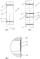
- FIG. 1 illustrated chimney pipe 2 extends in the longitudinal direction from a lower connecting end with a conical plug portion 4 to an upper cylindrical connecting end 6.
- a middle part 8 is arranged, which is separated to the two ends 4, 8 by a peripheral bead 10.
- the middle part 8 is formed strictly cylindrical and aligned with the cylindrical connecting end 6. Both subsections therefore have consistently the same (circle) cross section, in particular inner cross section.
- the conical plug-in region 4 extends in the longitudinal direction from the end-side end of the chimney pipe 2 to the beginning of the lower bead 10.
- the axial length is typically in the range of about 75mm.
- the chimney pipe 2 has in the conical plug-in area a cone angle ⁇ , which is 1 in the exemplary embodiment. In FIG. 1 the double cone angle 2 ⁇ is shown.
- FIG. 3 shows, in the mounted state, the cylindrical connecting end 6 hugs the outside of the conical plug-in area 4.
- the conical plug-in area 4 therefore expands the cylindrical connecting end 6 at least at the upper, end-side connecting end somewhat.
- the inner diameter of the conical plug-in area 4 at its upper, the bead 10 facing foot region, where the conical plug portion 4 has the largest diameter, is preferably identical to the inner diameter of the central part and the cylindrical connecting end 6.
- the conical plug portion 4 is therefore aligned with the cylindrical center part 8.
- the conical plug-in area 4 at its foot with the largest diameter has a larger by twice the wall thickness of the chimney pipe outer diameter compared to the inner diameter of the cylindrical connecting end 6, resulting in the radial expansion and conical adjustment of the cylindrical connecting portion 6 in the assembled final state leads. This ensures a reliable seal.
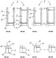
- FIGS. 4A-4D in addition to the FIGS. 5A-5D show different embodiments of the single-wall chimney 2.
- the FIG. 4A with associated FIG. 5A shows a chimney pipe 2, which has a bead 10 only at the lower conical connection end 4.
- the opposite end region is free of a bead 10.
- the middle part 8 is therefore identical in the cylindrical connection end 6 via. These are indistinguishable.
- FIG. 4B shows a variant in which in the region of the cylindrical connecting end 6, a circumferential bead 10 is formed.
- the two beads 10 are at least approximately equidistant from the opposite ends of the chimney pipe.
- the Figures 6A-6D show a double-walled variant of a chimney pipe 2, for example, for outdoor use.
- the respective chimney pipe 2 then has an inner tube 14, an outer tube 16 and an insulating intermediate layer 18.
- the inner tube 14 is in each case corresponding to that of the FIGS. 4A-4D described chimney pipe 2 is formed.
- the in the FIGS. 4A-4D illustrated chimney pipes 2 can therefore be used without further changes for a double-walled variant embodiment.
- the insulation intermediate layer 18 in the conical plug-in region 4 is no longer continued.
- There is a space between inner tube 14 and outer tube 16 is formed. This is slipped when mating two chimney pipes 2 on the opposite cylindrical connecting end 6, so that the portion of the outer tube 16, the cylindrical end of the associated outer tube 16 on the outside and the conical mating portion 4 of the inner tube 14 in turn inside the cylindrical connecting end 6 of the associated inner tube 14 engages.
- the insulating intermediate layer 18 is carried out without interruption up to the upper end edge in the region of the cylindrical connecting end 6.
- Both the outer tube 16 and the inner tube 14 are formed in the region of the cylindrical connecting end 6 continuously cylindrical and aligned in particular each with a respective central part 8 of the inner tube 14 and the outer tube sixteenth
- the outer tube 16 at the end face in the conical plug-in portion 4 a trained in the manner of a chamfer 20 radial expansion. This facilitates in particular in combination with the radially inwardly drawn chamfer 12 on the inner tube 14, the assembly.
Landscapes
- Engineering & Computer Science (AREA)
- General Engineering & Computer Science (AREA)
- Mechanical Engineering (AREA)
- Thermal Insulation (AREA)
- Rigid Pipes And Flexible Pipes (AREA)
- Chimneys And Flues (AREA)
Description
- Die Erfindung betrifft ein Kaminrohr insbesondere für einen Edelstahlabgasanlage mit zwei gegenüberliegenden Verbindungsenden zur Ausbildung einer Steckverbindung mit weiteren Kaminrohren sowie mit einem Mittenteil zwischen den Verbindungsenden. Die Erfindung betrifft weiterhin einen aus derartigen Kaminrohren zusammengesetzten Abgasanlage, insbesondere Edelstahl-Abgasanlage sowie ein Verfahren zum Herstellen einer solchen Abgasanlage.
- Zum Aufbau einer Metall-Abgasanlage oder Schornsteins, insbesondere Edelstahlabgasanlage, sowohl für Innen- als auch für Außenanwendung werden üblicherweise mehrere Kaminrohre ineinander gesteckt. Hierbei gibt es sowohl einwandige als auch doppelwandige Ausführungsvarianten. Bei der doppelwandigen Ausführungsvariante weist das Kaminrohr ein Innenrohr sowie ein Außenrohr und eine dazwischen angeordnete Isolationszwischenlage auf. Doppelwandige Abgasanlagensysteme werden insbesondere für den Außenbereich vorgesehen.
- Derartige Abgasanlagensysteme sind beispielsweise zu entnehmen aus der
DE 94 19 304 U1 , derDE 295 22 176 U1 und derEP 0 798 513 A2 . Aus letzterer ist ein doppelwandiges System zu entnehmen. - Zur Ausbildung von dichten Steckverbindungen zwischen den einzelnen Kaminrohren weisen diese endseitig jeweils Steckmuffen auf, die typischerweise konisch aufgeweitet bzw. konisch verjüngend ausgebildet sind.
- Um für unterschiedliche Anforderungen universell einsetzbar zu sein, sind derartige Abgasanlagensysteme insgesamt aus mehreren Modulbauteilen zusammengesetzt. So werden typischerweise unterschiedlich lange Kaminrohre vorgehalten, um eine Abgasanlage mit einer gewünschten Gesamt-Länge ausbilden zu können.
- Ausgehend hiervon liegt der Erfindung die Aufgabe zu Grunde, ein flexibles Kaminrohr-System zu ermöglichen.
- Aus der
US 1 854 515 A sind emaillierte Ofenrohre zu entnehmen, welche die Merkmale des Oberbegriffs des Anspruchs 1 offenbaren und welche insgesamt konisch verlaufen, so dass sie an ihrem einen Ende eine größeren Innendurchmesser als Außendurchmesser am gegenüberliegenden Ende aufweisen und dadurch ineinander gesteckt werden können. Im Verbindungsbereich ist weiterhin in bevorzugter Ausgestaltung ein elastisches Dichtmittel angeordnet.
Aus derDE 201 12 692 U1 sind Abgasrohre zu entnehmen, die zum Ineinanderstecken an ihren gegenüberliegenden Enden jeweils zueinander passende konische Abschnitte aufweisen, die jeweils eine schraubenlinienförmige Sicke aufweisen, über die die beiden Enden nach Art eines Schraubvorgangs ineinandergezogen werden.
Weitere Abgasrohre, die durch Ineinanderstecken zusammengefügt werden sind beispielsweise zu entnehmen ausDE 10 2004 028 385 A1 oder ausUS 2008/0007055 A1 .
Die Aufgabe wird gemäß der Erfindung gelöst durch ein Kaminrohr, insbesondere für eine Edelstahlabgasanlage mit den Merkmalen des Anspruchs 1. Das Kaminrohr weist zwei gegenüberliegende Verbindungsenden auf zur Ausbildung einer Steckverbindung mit weiteren Kaminrohren sowie ein Mittelteil zwischen den Verbindungsenden, wobei das erste, im montierten Zustand untere Verbindungsende einen konischen Steckbereich ausbildet und das zweite, gegenüberliegende und im Montageendzustand obere Verbindungsende zylindrisch ausgebildet ist.
Im Hinblick auf eine zuverlässige, sichere Abdichtung ist in der montierten Position zweier ineinander gesteckter Kaminrohre das zylindrische Verbindungsende durch das konische Verbindungsende etwas konisch aufgeweitet. Das zylindrische Verbindungsende passt sich daher dem konischen Verbindungsende an. Letzteres weitet daher nach Art einer Matrize das zylindrische Verbindungsende beim Einstecken etwas auf, so dass sich die beiden Verbindungsenden dichtend aneinander legen. - Durch die nur einseitige konische Ausgestaltung wird weiterhin eine zuverlässige, gasdichte Steckverbindung zwischen zwei aufeinander folgenden Kaminrohren sicher gestellt. Zur gasdichten Abdichtung sind neben dem Ineinanderstecken der Kaminrohre vorzugsweise keine weiteren Maßnahmen erforderlich und vorgesehen. Das konische Verbindungsende wird dabei in das zylindrische Verbindungsende eines zweiten Kaminrohrs eingesteckt. Durch die rein zylindrische Ausbildung des oberen Verbindungsendes wird der besondere Vorteil erzielt, dass das Kaminrohr selbst ohne Probleme auf eine gewünschte Länge kürzbar ist. Gleichzeitig bleibt die volle Funktion beibehalten, so dass unmittelbar vor Ort auf der Baustelle das jeweilige Kaminrohr exakt auf die gewünschte Länge abgelängt werden kann.
- Aufgrund der zylindrischen Ausgestaltung des Kaminrohrs im Bereich des zweiten Verbindungsendes kann es an dieser Seite gekürzt werden, ohne dass weitere Maßnahmen zur Ausbildung eines neuen zylindrischen Verbindungsendes erforderlich sind. Das Rohrende bildet daher an der Trennstelle ohne weitere Maßnahmen ein neues zylindrisches Verbindungsende aus.
- Hierzu ist zweckdienlicherweise vorgesehen, dass der Innendurchmesser des zylindrischen Verbindungsendes identisch zu dem Innendurchmesser des Mittenteils ist. Das zylindrische Verbindungsende fluchtet daher mit dem Mittenteil.
- Im Hinblick auf eine zuverlässige, sichere Abdichtung ist in der montierten Position zweier ineinander gesteckter Kaminrohre das zylindrische Verbindungsende durch das konische Verbindungsende etwas konisch aufgeweitet. Das zylindrische Verbindungsende passt sich daher dem konischen Verbindungsende an. Letzteres weitet daher nach Art einer Matrize das zylindrische Verbindungsende beim Einstecken etwas auf, so dass sich die beiden Verbindungsenden dichtend aneinander legen.
- Um ein einfaches Einführen des konischen Verbindungsendes in das zylindrische Verbindungsende zu ermöglichen weist der konische Steckbereich endseitig vorzugsweise eine radial nach innen geneigte Einführphase auf, welche einen größeren Neigungswinkel als der eigentliche konische Steckbereich aufweist.
- Ergänzend ist in der bevorzugten Weiterbildung im konischen Steckbereich eine umlaufende Rille ausgebildet, welche als Kapillarsperre wirkt.
- Ergänzend ist weiterhin zumindest an einem Verbindungsende eine umlaufende Sicke ausgebildet, welche zur Montage insbesondere eines Klemmbandes oder auch einer Befestigungsschelle dient. Die umlaufende Sicke schließt sich mittelbar an den konischen Steckbereich an, bevorzugt diesen also. Sie ist dabei in der Innenwandung durch eine Umformung ausgebildet, so dass an der Außenseite eine ringförmig umlaufende Rippe ausgebildet ist.
- Grundsätzlich kann und ist in bevorzugter Ausgestaltung im Bereich des zylindrischen Verbindungsendes ebenfalls eine solche Sicke ausgebildet. Bei Bedarf besteht weiterhin die Möglichkeit, das Kaminrohr an diesem zylindrischen Ende anzulängen. Aufgrund der miteinander fluchtenden Innendurchmesser ist die Funktion der Steckverbindung unabhängig von der Anordnung der umlaufenden Sicke im Bereich des zylindrischen Verbindungsendes.
- Bevorzugt ist jedoch eine Ausgestaltung, bei der eine derartige umlaufende Sicke im zylindrischen Endbereich nicht vorgesehen ist.
- Der Konuswinkel des konischen Steckbereichs liegt üblicherweise im Bereich von 0,5° - 3° und insbesondere im Bereich von 1°. Weiterhin weist der konische Steckbereich eine axiale Länge im Bereich vom 40mm - 100mm auf und liegt beispielsweise typischerweise bei 75mm bei einem Innenrohr-Durchmesser von beispielsweise 150mm.
- Die Ausgestaltung mit dem zylindrischen Verbindungsende wird vorzugsweise für einwandige Kaminrohre herangezogen. In einer alternativen bevorzugten Ausgestaltung ist das Kaminrohr aber auch als doppelwandiges Kaminrohr mit einem Innenrohr, einem Außenrohr und einer Isolationszwischenlage ausgebildet.
- Bei dieser Ausgestaltung ist vorzugsweise lediglich das Innenrohr mit dem konischen und dem zylindrischen Verbindungsende ausgebildet. Diese Ausgestaltung erlaubt also auch ein vereinfachtes Zusammenstecken von doppelwandigen Kaminrohren und ermöglicht gleichzeitig ein bedarfsweises Ablängen derartiger doppelwandiger Kaminrohre.
- Zur Ausbildung der Steckverbindung ist dabei im konischen Steckbereich keine Isolationszwischenlage zwischen Außenrohr und Innenrohr ausgebildet. Zum Zusammenstecken wird das Außenrohr im Bereich des konischen Verbindungsendes über das zugeordnete Außenrohr des anderen Kaminrohrs an dessen zylindrischen Verbindungsende geschoben. Der konische Steckbereich wird daher bei dem Innenrohrer innenseitig eingesteckt und das Außenrohr außenseitig aufgesteckt.
- Für eine einfache Montage ist das Außenrohr im Bereich des konischen Verbindungsendes etwas radial aufgeweitet und weist eine entsprechend ausgebildete, radial nach außen aufgeweitete Fase auf. Unabhängig von dieser Fase ist das Außenrohr im konischen Steckbereich des Innenrohrs zylindrisch ausgebildet.
- Die Aufgabe wird erfindungsgemäß weiterhin gelöst durch eine Abgasanlage, insbesondere Edelstahlabgasanlage, sowie durch ein Verfahren zur Herstellung einer derartigen Abgasanlage, mit mehreren derartigen Kaminrohren, welche ineinander gesteckt sind.
- Das gesamte Abgasanlagensystem zeichnet sich durch eine einfache Ablängbarkeit der einzelnen Kaminrohre auf Grund des rein zylindrischen Verbindungsendes aus. Gleichzeitig ist eine zuverlässige Abdichtung im Steckverbindungsbereich gewährleistet. Dies erfolgt insbesondere ausschließlich durch die konisch-zylindrische Passung, wobei bei der Montage insbesondere eine konische Verformung des zylindrischen Bereichs erfolgt.
- Ein derartiges Abgasanlagensystem lässt sich sowohl für Unterdruck- als auch für Überdruck-Anwendungen einsetzen. Bei Bedarf können zusätzliche Dichtelemente im Steckverbindungsbereich angeordnet sein.
- Die im Hinblick auf das Kaminrohr angeführten Vorteile und bevorzugten Ausgestaltungen sind sinngemäß auch auf die Abgasanlage sowie auf das Verfahren zu übertragen.
- Ausführungsbeispiele der Erfindung werden im Folgenden anhand der Figuren näher erläutert. Diese zeigen:
- Figur 1
- ein Kaminrohr in Seitendarstellung,
- Figur 2
- zwei zusammengesetzte Kaminrohre in einer unterbrochenen Seiten-Darstellung,
- Figur 3
- eine vergrößerte Darstellung des Steckverbindungsbereichs zwischen den beiden Kaminrohren gemäß
Figur 2 , - Figuren 4A - 4D
- unterschiedliche Ausführungsvarianten eines einwandigen Kaminrohrs,
- Figuren 5A - 5D
- vergrößerte Darstellungen des jeweils mit einem Kreis in den
Figuren 4A - 4D gekennzeichneten Bereichs, - Figuren 6A - 6D
- unterschiedliche Ausführungsvarianten eines doppelwandigen Kaminrohrs sowie
- Figuren 7A - 7D
- vergrößerte Darstellungen des jeweils mit einem Kreis in den
Figuren 6A - 6D gekennzeichneten Bereichs. - Das in
Figur 1 dargestellte Kaminrohr 2 erstreckt sich in Längsrichtung von einem unteren Verbindungsende mit einem konischen Steckbereich 4 bis zu einem oberen zylindrischen Verbindungsende 6. Dazwischen ist ein Mittenteil 8 angeordnet, welcher zu den beiden Enden 4, 8 durch eine umlaufende Sicke 10 abgetrennt ist. Der Mittenteil 8 ist dabei streng zylindrisch ausgebildet und fluchtet mit dem zylindrischen Verbindungsende 6. Beide Teilbereiche weisen daher durchgehend den gleichen (Kreis) Querschnitt, insbesondere Innenquerschnitt auf. Der konische Steckbereich 4 erstreckt sich in Längsrichtung von dem stirnseiten Ende des Kaminrohrs 2 bis zum Beginn der unteren Sicke 10. Die axiale Länge liegt dabei typischerweise im Bereich von etwa 75mm. - Das Kaminrohr 2 weist im konischen Steckbereich einen Konuswinkel α auf, der im Ausführungsbeispiel bei 1 liegt. In
Figur 1 ist der doppelte Konuswinkel 2α eingezeichnet. - Wie insbesondere aus den vergrößerten Darstellungen der
Figur 3 hervorgeht, schmiegt sich im montierten Zustand das zylindrische Verbindungsende 6 außen an den konischen Steckbereich 4 an. Der konische Steckbereich 4 weitet daher das zylindrische Verbindungsende 6 zumindest am oberen, stirnseitigen Verbindungsende etwas auf. Der Innendurchmesser des konischen Steckbereichs 4 an seinem oberen, der Sicke 10 zugewandten Fußbereich, wo der konische Steckbereich 4 den größten Durchmesser aufweist, ist vorzugsweise identisch zu dem Innendurchmesser des Mittenteils und des zylindrischen Verbindungsendes 6. Der konische Steckbereich 4 fluchtet daher mit dem zylindrischen Mittenteil 8. Durch diese Maßnahme hat der konische Steckbereich 4 an seinem Fußbereich mit dem größten Durchmesser einen um die doppelte Wandstärke des Kaminrohres größeren Außendurchmesser im Vergleich zum Innendurchmesser des zylindrischen Verbindungsendes 6, was zu der radialen Aufweitung und konischen Anpassung des zylindrischen Verbindungsbereichs 6 im montieren Endzustand führt. Dadurch ist eine zuverlässige Abdichtung sichergestellt. - Die
Figuren 4A - 4D in Ergänzung zu denFiguren 5A - 5D zeigen unterschiedliche Ausführungsvarianten des einwandige Kaminrohrs 2. DieFigur 4A mit zugehörigenFigur 5A zeigt dabei ein Kaminrohr 2, welches lediglich am unteren konischen Verbindungsende 4 eine Sicke 10 aufweist. Der dessen gegenüberliegende Endbereich ist frei von einer Sicke 10. Der Mittenteil 8 geht daher identisch in das zylindrische Verbindungsende 6 über. Diese sind ununterscheidbar ausgebildet. - Weiterhin ist aus der vergrößerten Darstellung gemäß der
Figur 5A zu erkennen, däss stirnseitig der konische Steckbereich 4 eine Einführfase 12 aufweist, welche das Einstecken in das jeweilige zylindrische Verbindungsende 6 eines zugeordneten Kaminrohrs 2 erleichtert. -
Figur 4B zeigt eine Ausführungsvariante, bei der auch im Bereich des zylindrischen Verbindungsendes 6 eine umlaufende Sicke 10 ausgebildet ist. Die beiden Sicken 10 sind dabei zumindest etwa gleich weit von den gegenüberliegenden stirnseitigen Enden des Kaminrohrs beabstandet. - Die
Figuren 4C und 4D zeigen zu denFiguren 4A und 4B vergleichbare Ausführungsvarianten, wobei hier jedoch der konische Steckbereich 4 geradlinig zum Stirnrand ausläuft, also keine endseitige Einführfase 12 aufweist. - Die
Figuren 6A - 6D zeigen eine doppelwandige Ausführungsvariante eines Kaminrohrs 2 beispielsweise für die Außenanwendung. Das jeweilige Kaminrohr 2 weist danach ein Innenrohr 14, ein Außenrohr 16 sowie eine Isolationszwischenlage 18 auf. Das Innenrohr 14 ist dabei jeweils entsprechend dem zu denFiguren 4A - 4D beschriebenen Kaminrohr 2 ausgebildet. Die in denFiguren 4A - 4D dargestellten Kaminrohre 2 können daher ohne weitere Änderungen auch für eine doppelwandige Ausführungsvariante herangezogen werden. - Wie aus den
Figuren 6A - 6D und insbesondere auch in Kombination mit den Figuren 7A -7D zu entnehmen ist, ist die Isolationszwischenlage 18 im konischen Steckbereich 4 nicht mehr weitergeführt. Dort ist ein Freiraum zwischen Innenrohr 14 und Außenrohr 16 ausgebildet. Dieser wird beim Zusammenstecken zweier Kaminrohre 2 über das gegenüberliegende zylindrische Verbindungsende 6 gestülpt, so dass also der Abschnitt des Außenrohrs 16 das zylindrische Ende des zugeordneten Außenrohrs 16 außenseitig umfasst und der konische Steckbereich 4 des Innenrohrs 14 wiederrum innenseitig in das zylindrische Verbindungsende 6 des zugeordneten Innenrohrs 14 eingreift. Gleichzeitig ist die Isolationszwischenlage 18 unterbrechungsfrei bis zu dem oberen Stirnrand im Bereich des zylindrischen Verbindungsendes 6 durchgeführt. Sowohl das Außenrohr 16 als auch das Innenrohr 14 sind im Bereich des zylindrischen Verbindungsendes 6 durchgehend zylindrischen ausgebildet und fluchten insbesondere jeweils mit einem jeweiligen Mittenteil 8 des Innenrohrs 14 sowie des Außenrohrs 16. - Wie insbesondere aus den vergrößerten Darstellungen der
Figuren 7A - 7D zu entnehmen ist, weist das Außenrohr 16 stirnendseitig im konischen Steckbereich 4 eine nach Art einer Fase 20 ausgebildete radiale Aufweitung auf. Dies erleichtert insbesondere auch in Kombination mit der radial nach innen gezogenen Fase 12 am Innenrohr 14 die Montage. -
- 2
- Kaminrohr
- 4
- konischer Steckbereich
- 6
- zylindrisches Verbindungselementende
- 8
- Mittenteil
- 10
- Sicke
- 12
- Einführfase
- 14
- Innenrohr
- 16
- Außenrohr
- 18
- Isolationszwischenlage
- 20
- Fase
- α
- Konuswinkel
Claims (15)
- Kaminrohr (2) insbesondere für einen Edelstahl-Abgasanlage mit zwei gegenüberliegenden Verbindungsenden (4, 6) zur Ausbildung einer Steckverbindung mit weiteren Kaminrohren (2) sowie mit einem Mittenteil (8) zwischen den Verbindungsenden (4, 6),
dadurch gekennzeichnet,
dass das erste Verbindungsende (4) einen konischen Steckbereich (4) aufweist und das zweite Verbindungsende (6) im Ausgangszustand zylindrisch ausgebildet ist, wobei das erste und das zweite Verbindungsende (4,6) derart ausgebildet sind, dass zur Ausbildung der Steckverbindung zwischen dem Kaminrohr (2) und einem weiteren Kaminrohr (2), welches auch ein erstes Verbindungsende (4) wie das Kaminrohr (2) und ein zweites Verbindungsende (6) wie das Kaminrohr (2) aufweist, so dass beim Verbinden des Kaminrohrs (2) mit dem weiteren Kaminrohr (2) das zylindrische Verbindungsende (6) des einen Kaminrohrs (2) durch den konischen Steckbereich (4) des weiteren Kaminrohrs (2) konisch aufgeweitet wird, so dass bei den ineinander gesteckten Kaminrohren (2) die beiden Verbindungsenden (4,6) dichtend aneinander anliegen. - Kaminrohr (2) nach Anspruch 1,
dadurch gekennzeichnet,
dass es auf der dem zylindrischen Verbindungsende (6) zugewandten Seite ablängbar ist und das Rohrende an der Trennstelle ohne weitere Maßnahmen ein neues zylindrisches Verbindungsende (6) ausbildet. - Kaminrohr (2) nach einem der Ansprüche 1 oder 2,
dadurch gekennzeichnet,
dass der Innendurchmesser des zylindrischen Verbindungsendes (6) identisch zu dem Innendurchmesser des Mittenteils (8) ist. - Kaminrohr (2) nach einem der vorhergehenden Ansprüche,
dadurch gekennzeichnet,
dass der konische Steckbereich (4) endseitig eine radial nach innen geneigte Einführfase (12) aufweist. - Kaminrohr (2) nach einem der vorhergehenden Ansprüche, wobei im konischen Steckbereich (4) eine umlaufende Rille als Kapillarsperre ausgebildet ist.
- Kaminrohr (2) nach einem der vorhergehenden Ansprüche,
dadurch gekennzeichnet,
dass anschließend an zumindest einem der Verbindungsenden (4,6) eine umlaufende Sicke (10) ausgebildet ist. - Kaminrohr (2) nach Anspruch 6,
dadurch gekennzeichnet,
dass im Bereich des zylindrischen Verbindungsendes (6) keine Sicke (10) ausgebildet ist. - Kaminrohr (2) nach einem der vorhergehenden Ansprüche,
dadurch gekennzeichnet,
dass der konische Steckbereich einen Konuswinkel (α) im Bereich von 0,5° bis 3°, insbesondere von 1° aufweist und dass der konische Steckbereich (4) eine axiale Länge im Bereich von 40 mm bis 100 mm aufweist. - Kaminrohr (2) nach einem der vorhergehenden Ansprüche,
dadurch gekennzeichnet,
dass es als doppelwandiges Kaminrohr (2) mit einem Innenrohr (14), einem Außenrohr (16) und einer Isolationszwischenlage (18) ausgebildet ist. - Kaminrohr (2) nach Anspruch 9,
dadurch gekennzeichnet,
dass das Innenrohr (14) mit dem konischen Steckbereich (4) ausgebildet ist. - Kaminrohr (2) nach Anspruch 9 oder 10,
dadurch gekennzeichnet,
dass im konischen Steckbereich (4) keine Isolationszwischenlage (18) zwischen Außenrohr (16) und Innenrohr (14) ausgebildet ist. - Kaminrohr (2) nach einem der Ansprüche 9 bis 11,
dadurch gekennzeichnet,
dass das Außenrohr (16) endseitig im Bereich des konischen Verbindungsendes (4) eine radial nach außen aufgeweitete Fase (20) aufweist. - Abgasanlage, insbesondere Edelstahl-Abgasanlage, mit mehreren Kaminrohren (2) nach einem der vorhergehenden Ansprüche, wobei das erste Verbindungsende eines ersten Kaminrohres (2) mit seinem konischen Steckbereich (4) in das zweite Verbindungsende (6) eines zweiten Kaminrohres (2) eingesteckt ist, wobei hierdurch das zweite Verbindungsende (6) konisch aufgeweitet ist, so dass die beiden Verbindungsenden dichtend aneinander anliegen.
- Verfahren zur Herstellung einer Abgasanlage unter Verwendung mehrerer Kaminrohre (2) nach einem der Ansprüche 1 bis 13, bei dem zwei Kaminrohre (2) ineinander gesteckt werden und hierbei das zylindrische Verbindungsende (6) des ersten Kaminrohrs (2) durch den konischen Steckbereich (4) des zweiten Kaminrohrs (2) konisch aufgeweitet wird, so dass sich die beiden Verbindungsenden dichtend aneinander legen.
- Verfahren nach Anspruch 14, bei dem eines der Kaminrohre (2) auf der Seite des zweiten Verbindungsendes (6) abgelängt wird und durch das Ablängen ein neues, zylindrischen zweites Verbindungsende (6) ausgebildet wird, welches mit einem konischen Steckbereich (4) eines ersten Verbindungsendes des zweiten Kaminrohrs (2) durch Stecken verbunden wird.
Applications Claiming Priority (2)
| Application Number | Priority Date | Filing Date | Title |
|---|---|---|---|
| DE202013002004U DE202013002004U1 (de) | 2013-03-04 | 2013-03-04 | Kaminrohr sowie Abgasanlage mit einem solchen Kaminrohr |
| PCT/EP2014/000526 WO2014135259A2 (de) | 2013-03-04 | 2014-02-28 | Kaminrohr sowie abgasanlage und verfahren zur herstellung einer abgasanlage mit einem solchen kaminrohr |
Publications (2)
| Publication Number | Publication Date |
|---|---|
| EP2965005A2 EP2965005A2 (de) | 2016-01-13 |
| EP2965005B1 true EP2965005B1 (de) | 2018-08-29 |
Family
ID=48465184
Family Applications (1)
| Application Number | Title | Priority Date | Filing Date |
|---|---|---|---|
| EP14712202.2A Not-in-force EP2965005B1 (de) | 2013-03-04 | 2014-02-28 | Kaminrohr sowie abgasanlage und verfahren zur herstellung einer abgasanlage mit einem solchen kaminrohr |
Country Status (4)
| Country | Link |
|---|---|
| US (1) | US20150369481A1 (de) |
| EP (1) | EP2965005B1 (de) |
| DE (1) | DE202013002004U1 (de) |
| WO (1) | WO2014135259A2 (de) |
Families Citing this family (2)
| Publication number | Priority date | Publication date | Assignee | Title |
|---|---|---|---|---|
| DE102017207053B4 (de) | 2017-04-26 | 2019-10-31 | Jeremias GmbH Fachgroßhandel für Schornsteinbedarf | Abgasrohr sowie Verfahren zum Ablängen eines Abgasrohres |
| US12460760B2 (en) * | 2022-12-20 | 2025-11-04 | The Yokohama Rubber Co., Ltd. | Attachment for fluid characteristic measurement sensor |
Family Cites Families (20)
| Publication number | Priority date | Publication date | Assignee | Title |
|---|---|---|---|---|
| US1528252A (en) * | 1925-03-03 | Clean-out elbow | ||
| US335631A (en) * | 1886-02-09 | of poet chester | ||
| US183494A (en) * | 1876-10-24 | Improvement in stove-pipe joints | ||
| US1854515A (en) * | 1930-02-03 | 1932-04-19 | Jackes Evans Mfg Company | Pipe joint |
| US4099747A (en) * | 1976-11-12 | 1978-07-11 | Johns-Manville Corporation | Air duct connecting assembly |
| US4306491A (en) * | 1979-11-26 | 1981-12-22 | Reardon Jr Charles A | Flue system for wood burning stoves |
| US4437687A (en) * | 1980-11-24 | 1984-03-20 | Wilson James H | Waterproof assembly or sealing an aperture housing a conduit |
| US4424794A (en) * | 1981-04-13 | 1984-01-10 | Vermont Castings, Inc. | Fireplace adapter |
| FR2565327B3 (fr) * | 1984-06-01 | 1986-12-19 | Tolerie Forezienne Sa | Conduit de fumee perfectionne metallique simple paroi |
| US4846147A (en) * | 1987-10-05 | 1989-07-11 | Simpson Dura Vent Company, Inc. | Chimney liner system |
| DE4332007C2 (de) * | 1993-01-26 | 1997-01-30 | Ero Edelstahl Rohrtechnik Gmbh | Vorrichtung zum Ausgleichen von Rohrleitungslängen |
| DE29522176U1 (de) | 1994-05-24 | 2000-06-08 | SEM Schneider Elementebau GmbH & Co. KG, 41238 Mönchengladbach | Vorrichtung zur Verbindung von Rohrleitungsabschnitten untereinander |
| DE9419304U1 (de) | 1994-12-02 | 1995-02-16 | Karl Schräder Nachf. KG, 59174 Kamen | Kaminrohr für die Schornsteinsanierung |
| DE19611580C1 (de) | 1996-03-23 | 1997-10-30 | Karl Schraeder Nachf Inh Karl | Rohrabschnitt eines doppelwandigen Kaminrohrs für den Schornsteinbau |
| DE20112692U1 (de) * | 2001-07-31 | 2001-10-31 | Härtig, Otto, 04209 Leipzig | Abgasrohr aus mehreren Rohrabschnitten |
| US6719330B2 (en) * | 2002-06-18 | 2004-04-13 | Qest | Flexible tubing/fitting connection |
| DE102004028385A1 (de) * | 2004-06-14 | 2006-01-05 | Tona Tonwerke Schmitz Gmbh | Kamin-Rauchgasrohr |
| JP4758094B2 (ja) * | 2004-11-26 | 2011-08-24 | トーセツ株式会社 | 給排気管 |
| CA2619274C (en) * | 2007-04-11 | 2010-04-13 | Don Park Limited Partnership | Chimney lining and venting apparatus for use with emissions from an appliance, and method of assembly |
| US9534392B2 (en) * | 2014-02-24 | 2017-01-03 | Liberty Diversified International, Inc. | Telescoping pipe boot |
-
2013
- 2013-03-04 DE DE202013002004U patent/DE202013002004U1/de not_active Expired - Lifetime
-
2014
- 2014-02-28 WO PCT/EP2014/000526 patent/WO2014135259A2/de not_active Ceased
- 2014-02-28 EP EP14712202.2A patent/EP2965005B1/de not_active Not-in-force
-
2015
- 2015-08-28 US US14/839,049 patent/US20150369481A1/en not_active Abandoned
Also Published As
| Publication number | Publication date |
|---|---|
| DE202013002004U1 (de) | 2013-04-24 |
| WO2014135259A2 (de) | 2014-09-12 |
| US20150369481A1 (en) | 2015-12-24 |
| WO2014135259A3 (de) | 2014-10-30 |
| EP2965005A2 (de) | 2016-01-13 |
Similar Documents
| Publication | Publication Date | Title |
|---|---|---|
| EP2330326B1 (de) | Rohrförmiges Bauteil | |
| DE102014100028B4 (de) | Klemmring, Schiebehülse, Anordnung sowie Verfahren zur Herstellung einer unlösbaren Verbindung | |
| EP2965005B1 (de) | Kaminrohr sowie abgasanlage und verfahren zur herstellung einer abgasanlage mit einem solchen kaminrohr | |
| EP3199772B1 (de) | Schalldämpfer für eine abgasanlage | |
| EP1907742B1 (de) | Biegbarer schlauch sowie verfahren zum montieren einer überwurfmutter auf einen biegbaren schlauch | |
| DE102012110086A1 (de) | Hülse für unlösbare Verbindung, Verfahren zur Herstellung einer Hülse und System mit einer Hülse | |
| DE19547677C2 (de) | Kaminrohr für die Schornsteinsanierung | |
| EP1642057B1 (de) | Anschlussverbindung für ringgewellte schlauchleitungen | |
| EP0798513A2 (de) | Rohrabschnitt eines doppelwandigen Kaminrohrs für den Schornsteinbau | |
| DE102017207053B4 (de) | Abgasrohr sowie Verfahren zum Ablängen eines Abgasrohres | |
| EP0443222A1 (de) | Doppelwandiger Rohrabschnitt für eine Rohrleitung insbesondere einen Schornstein. | |
| EP3012502A1 (de) | Schlauch und anschlussvorrichtung für einen schlauch | |
| EP2549164A2 (de) | Fluidleitungselement und Verfahren zu dessen Herstellung | |
| EP2169291B1 (de) | Rohrförmiges Übergangsstück und zusammensetzbares Rohrsystem | |
| EP1518069B1 (de) | Abdichtung für eine einsteckverbindung bei rohren | |
| DE60012835T2 (de) | Doppelwandiger Rohrabschnitt und Verfahren zur Herstellung von rohrförmigen Elementen | |
| EP2642173A1 (de) | Anschlussvorrichtung für einen ringgewellten Schlauch | |
| WO2024074297A1 (de) | Anschlussverbindung zwischen einem rohrwellschlauch und einem rohrleitungssystem | |
| EP3181971B1 (de) | Flexibles leitungselement mit einem modularen metallschlauch | |
| DE102015203851A1 (de) | Verbindungsanordnung | |
| EP3045796A1 (de) | Abgasrohr, Abgasrohrsystem sowie Demontageverfahren | |
| DE20112692U1 (de) | Abgasrohr aus mehreren Rohrabschnitten | |
| DE202005005852U1 (de) | Rohrbausystem mit Rohrelementen aus Metallblech, insbesondere zur Herstellung eines Abgasrohres im Kaminbau | |
| DE102007013560B4 (de) | Einstellbarer Segmentbogen | |
| CH678220A5 (en) | Plug-in pipe connection - has one wider end gripping over the pipe and other end outwardly bent back and milled, with sprung tongues on sleeve |
Legal Events
| Date | Code | Title | Description |
|---|---|---|---|
| PUAI | Public reference made under article 153(3) epc to a published international application that has entered the european phase |
Free format text: ORIGINAL CODE: 0009012 |
|
| 17P | Request for examination filed |
Effective date: 20150909 |
|
| AK | Designated contracting states |
Kind code of ref document: A2 Designated state(s): AL AT BE BG CH CY CZ DE DK EE ES FI FR GB GR HR HU IE IS IT LI LT LU LV MC MK MT NL NO PL PT RO RS SE SI SK SM TR |
|
| AX | Request for extension of the european patent |
Extension state: BA ME |
|
| DAX | Request for extension of the european patent (deleted) | ||
| STAA | Information on the status of an ep patent application or granted ep patent |
Free format text: STATUS: EXAMINATION IS IN PROGRESS |
|
| 17Q | First examination report despatched |
Effective date: 20170516 |
|
| GRAP | Despatch of communication of intention to grant a patent |
Free format text: ORIGINAL CODE: EPIDOSNIGR1 |
|
| STAA | Information on the status of an ep patent application or granted ep patent |
Free format text: STATUS: GRANT OF PATENT IS INTENDED |
|
| INTG | Intention to grant announced |
Effective date: 20180327 |
|
| GRAS | Grant fee paid |
Free format text: ORIGINAL CODE: EPIDOSNIGR3 |
|
| GRAA | (expected) grant |
Free format text: ORIGINAL CODE: 0009210 |
|
| STAA | Information on the status of an ep patent application or granted ep patent |
Free format text: STATUS: THE PATENT HAS BEEN GRANTED |
|
| AK | Designated contracting states |
Kind code of ref document: B1 Designated state(s): AL AT BE BG CH CY CZ DE DK EE ES FI FR GB GR HR HU IE IS IT LI LT LU LV MC MK MT NL NO PL PT RO RS SE SI SK SM TR |
|
| REG | Reference to a national code |
Ref country code: GB Ref legal event code: FG4D Free format text: NOT ENGLISH |
|
| REG | Reference to a national code |
Ref country code: CH Ref legal event code: EP |
|
| REG | Reference to a national code |
Ref country code: AT Ref legal event code: REF Ref document number: 1035562 Country of ref document: AT Kind code of ref document: T Effective date: 20180915 |
|
| REG | Reference to a national code |
Ref country code: IE Ref legal event code: FG4D Free format text: LANGUAGE OF EP DOCUMENT: GERMAN |
|
| REG | Reference to a national code |
Ref country code: DE Ref legal event code: R096 Ref document number: 502014009311 Country of ref document: DE |
|
| REG | Reference to a national code |
Ref country code: NL Ref legal event code: MP Effective date: 20180829 |
|
| REG | Reference to a national code |
Ref country code: LT Ref legal event code: MG4D |
|
| PG25 | Lapsed in a contracting state [announced via postgrant information from national office to epo] |
Ref country code: BG Free format text: LAPSE BECAUSE OF FAILURE TO SUBMIT A TRANSLATION OF THE DESCRIPTION OR TO PAY THE FEE WITHIN THE PRESCRIBED TIME-LIMIT Effective date: 20181129 Ref country code: SE Free format text: LAPSE BECAUSE OF FAILURE TO SUBMIT A TRANSLATION OF THE DESCRIPTION OR TO PAY THE FEE WITHIN THE PRESCRIBED TIME-LIMIT Effective date: 20180829 Ref country code: NL Free format text: LAPSE BECAUSE OF FAILURE TO SUBMIT A TRANSLATION OF THE DESCRIPTION OR TO PAY THE FEE WITHIN THE PRESCRIBED TIME-LIMIT Effective date: 20180829 Ref country code: IS Free format text: LAPSE BECAUSE OF FAILURE TO SUBMIT A TRANSLATION OF THE DESCRIPTION OR TO PAY THE FEE WITHIN THE PRESCRIBED TIME-LIMIT Effective date: 20181229 Ref country code: RS Free format text: LAPSE BECAUSE OF FAILURE TO SUBMIT A TRANSLATION OF THE DESCRIPTION OR TO PAY THE FEE WITHIN THE PRESCRIBED TIME-LIMIT Effective date: 20180829 Ref country code: NO Free format text: LAPSE BECAUSE OF FAILURE TO SUBMIT A TRANSLATION OF THE DESCRIPTION OR TO PAY THE FEE WITHIN THE PRESCRIBED TIME-LIMIT Effective date: 20181129 Ref country code: FI Free format text: LAPSE BECAUSE OF FAILURE TO SUBMIT A TRANSLATION OF THE DESCRIPTION OR TO PAY THE FEE WITHIN THE PRESCRIBED TIME-LIMIT Effective date: 20180829 Ref country code: GR Free format text: LAPSE BECAUSE OF FAILURE TO SUBMIT A TRANSLATION OF THE DESCRIPTION OR TO PAY THE FEE WITHIN THE PRESCRIBED TIME-LIMIT Effective date: 20181130 Ref country code: LT Free format text: LAPSE BECAUSE OF FAILURE TO SUBMIT A TRANSLATION OF THE DESCRIPTION OR TO PAY THE FEE WITHIN THE PRESCRIBED TIME-LIMIT Effective date: 20180829 |
|
| PG25 | Lapsed in a contracting state [announced via postgrant information from national office to epo] |
Ref country code: AL Free format text: LAPSE BECAUSE OF FAILURE TO SUBMIT A TRANSLATION OF THE DESCRIPTION OR TO PAY THE FEE WITHIN THE PRESCRIBED TIME-LIMIT Effective date: 20180829 Ref country code: LV Free format text: LAPSE BECAUSE OF FAILURE TO SUBMIT A TRANSLATION OF THE DESCRIPTION OR TO PAY THE FEE WITHIN THE PRESCRIBED TIME-LIMIT Effective date: 20180829 Ref country code: HR Free format text: LAPSE BECAUSE OF FAILURE TO SUBMIT A TRANSLATION OF THE DESCRIPTION OR TO PAY THE FEE WITHIN THE PRESCRIBED TIME-LIMIT Effective date: 20180829 |
|
| PG25 | Lapsed in a contracting state [announced via postgrant information from national office to epo] |
Ref country code: EE Free format text: LAPSE BECAUSE OF FAILURE TO SUBMIT A TRANSLATION OF THE DESCRIPTION OR TO PAY THE FEE WITHIN THE PRESCRIBED TIME-LIMIT Effective date: 20180829 Ref country code: PL Free format text: LAPSE BECAUSE OF FAILURE TO SUBMIT A TRANSLATION OF THE DESCRIPTION OR TO PAY THE FEE WITHIN THE PRESCRIBED TIME-LIMIT Effective date: 20180829 Ref country code: ES Free format text: LAPSE BECAUSE OF FAILURE TO SUBMIT A TRANSLATION OF THE DESCRIPTION OR TO PAY THE FEE WITHIN THE PRESCRIBED TIME-LIMIT Effective date: 20180829 Ref country code: CZ Free format text: LAPSE BECAUSE OF FAILURE TO SUBMIT A TRANSLATION OF THE DESCRIPTION OR TO PAY THE FEE WITHIN THE PRESCRIBED TIME-LIMIT Effective date: 20180829 Ref country code: IT Free format text: LAPSE BECAUSE OF FAILURE TO SUBMIT A TRANSLATION OF THE DESCRIPTION OR TO PAY THE FEE WITHIN THE PRESCRIBED TIME-LIMIT Effective date: 20180829 Ref country code: RO Free format text: LAPSE BECAUSE OF FAILURE TO SUBMIT A TRANSLATION OF THE DESCRIPTION OR TO PAY THE FEE WITHIN THE PRESCRIBED TIME-LIMIT Effective date: 20180829 |
|
| PG25 | Lapsed in a contracting state [announced via postgrant information from national office to epo] |
Ref country code: SK Free format text: LAPSE BECAUSE OF FAILURE TO SUBMIT A TRANSLATION OF THE DESCRIPTION OR TO PAY THE FEE WITHIN THE PRESCRIBED TIME-LIMIT Effective date: 20180829 Ref country code: SM Free format text: LAPSE BECAUSE OF FAILURE TO SUBMIT A TRANSLATION OF THE DESCRIPTION OR TO PAY THE FEE WITHIN THE PRESCRIBED TIME-LIMIT Effective date: 20180829 Ref country code: DK Free format text: LAPSE BECAUSE OF FAILURE TO SUBMIT A TRANSLATION OF THE DESCRIPTION OR TO PAY THE FEE WITHIN THE PRESCRIBED TIME-LIMIT Effective date: 20180829 |
|
| REG | Reference to a national code |
Ref country code: DE Ref legal event code: R097 Ref document number: 502014009311 Country of ref document: DE |
|
| PLBE | No opposition filed within time limit |
Free format text: ORIGINAL CODE: 0009261 |
|
| STAA | Information on the status of an ep patent application or granted ep patent |
Free format text: STATUS: NO OPPOSITION FILED WITHIN TIME LIMIT |
|
| 26N | No opposition filed |
Effective date: 20190531 |
|
| PG25 | Lapsed in a contracting state [announced via postgrant information from national office to epo] |
Ref country code: SI Free format text: LAPSE BECAUSE OF FAILURE TO SUBMIT A TRANSLATION OF THE DESCRIPTION OR TO PAY THE FEE WITHIN THE PRESCRIBED TIME-LIMIT Effective date: 20180829 |
|
| REG | Reference to a national code |
Ref country code: DE Ref legal event code: R119 Ref document number: 502014009311 Country of ref document: DE |
|
| REG | Reference to a national code |
Ref country code: CH Ref legal event code: PL |
|
| GBPC | Gb: european patent ceased through non-payment of renewal fee |
Effective date: 20190228 |
|
| PG25 | Lapsed in a contracting state [announced via postgrant information from national office to epo] |
Ref country code: MC Free format text: LAPSE BECAUSE OF FAILURE TO SUBMIT A TRANSLATION OF THE DESCRIPTION OR TO PAY THE FEE WITHIN THE PRESCRIBED TIME-LIMIT Effective date: 20180829 Ref country code: LU Free format text: LAPSE BECAUSE OF NON-PAYMENT OF DUE FEES Effective date: 20190228 |
|
| REG | Reference to a national code |
Ref country code: BE Ref legal event code: MM Effective date: 20190228 |
|
| REG | Reference to a national code |
Ref country code: IE Ref legal event code: MM4A |
|
| PG25 | Lapsed in a contracting state [announced via postgrant information from national office to epo] |
Ref country code: LI Free format text: LAPSE BECAUSE OF NON-PAYMENT OF DUE FEES Effective date: 20190228 Ref country code: CH Free format text: LAPSE BECAUSE OF NON-PAYMENT OF DUE FEES Effective date: 20190228 |
|
| PG25 | Lapsed in a contracting state [announced via postgrant information from national office to epo] |
Ref country code: GB Free format text: LAPSE BECAUSE OF NON-PAYMENT OF DUE FEES Effective date: 20190228 Ref country code: IE Free format text: LAPSE BECAUSE OF NON-PAYMENT OF DUE FEES Effective date: 20190228 Ref country code: DE Free format text: LAPSE BECAUSE OF NON-PAYMENT OF DUE FEES Effective date: 20190903 |
|
| PG25 | Lapsed in a contracting state [announced via postgrant information from national office to epo] |
Ref country code: FR Free format text: LAPSE BECAUSE OF NON-PAYMENT OF DUE FEES Effective date: 20190228 Ref country code: BE Free format text: LAPSE BECAUSE OF NON-PAYMENT OF DUE FEES Effective date: 20190228 |
|
| PG25 | Lapsed in a contracting state [announced via postgrant information from national office to epo] |
Ref country code: TR Free format text: LAPSE BECAUSE OF FAILURE TO SUBMIT A TRANSLATION OF THE DESCRIPTION OR TO PAY THE FEE WITHIN THE PRESCRIBED TIME-LIMIT Effective date: 20180829 |
|
| REG | Reference to a national code |
Ref country code: AT Ref legal event code: MM01 Ref document number: 1035562 Country of ref document: AT Kind code of ref document: T Effective date: 20190228 |
|
| PG25 | Lapsed in a contracting state [announced via postgrant information from national office to epo] |
Ref country code: AT Free format text: LAPSE BECAUSE OF NON-PAYMENT OF DUE FEES Effective date: 20190228 |
|
| PG25 | Lapsed in a contracting state [announced via postgrant information from national office to epo] |
Ref country code: PT Free format text: LAPSE BECAUSE OF FAILURE TO SUBMIT A TRANSLATION OF THE DESCRIPTION OR TO PAY THE FEE WITHIN THE PRESCRIBED TIME-LIMIT Effective date: 20181229 Ref country code: MT Free format text: LAPSE BECAUSE OF FAILURE TO SUBMIT A TRANSLATION OF THE DESCRIPTION OR TO PAY THE FEE WITHIN THE PRESCRIBED TIME-LIMIT Effective date: 20180829 |
|
| PG25 | Lapsed in a contracting state [announced via postgrant information from national office to epo] |
Ref country code: CY Free format text: LAPSE BECAUSE OF FAILURE TO SUBMIT A TRANSLATION OF THE DESCRIPTION OR TO PAY THE FEE WITHIN THE PRESCRIBED TIME-LIMIT Effective date: 20180829 |
|
| PG25 | Lapsed in a contracting state [announced via postgrant information from national office to epo] |
Ref country code: HU Free format text: LAPSE BECAUSE OF FAILURE TO SUBMIT A TRANSLATION OF THE DESCRIPTION OR TO PAY THE FEE WITHIN THE PRESCRIBED TIME-LIMIT; INVALID AB INITIO Effective date: 20140228 |
|
| PG25 | Lapsed in a contracting state [announced via postgrant information from national office to epo] |
Ref country code: MK Free format text: LAPSE BECAUSE OF FAILURE TO SUBMIT A TRANSLATION OF THE DESCRIPTION OR TO PAY THE FEE WITHIN THE PRESCRIBED TIME-LIMIT Effective date: 20180829 |