EP2965097B1 - Procédé et appareil de mesure de valeurs quadratiques moyennes (rms) de courants à déclenchement en salve - Google Patents
Procédé et appareil de mesure de valeurs quadratiques moyennes (rms) de courants à déclenchement en salve Download PDFInfo
- Publication number
- EP2965097B1 EP2965097B1 EP14759463.4A EP14759463A EP2965097B1 EP 2965097 B1 EP2965097 B1 EP 2965097B1 EP 14759463 A EP14759463 A EP 14759463A EP 2965097 B1 EP2965097 B1 EP 2965097B1
- Authority
- EP
- European Patent Office
- Prior art keywords
- burst
- fired
- current
- rms
- currents
- Prior art date
- Legal status (The legal status is an assumption and is not a legal conclusion. Google has not performed a legal analysis and makes no representation as to the accuracy of the status listed.)
- Active
Links
Images





Classifications
-
- G—PHYSICS
- G01—MEASURING; TESTING
- G01R—MEASURING ELECTRIC VARIABLES; MEASURING MAGNETIC VARIABLES
- G01R19/00—Arrangements for measuring currents or voltages or for indicating presence or sign thereof
- G01R19/02—Measuring effective values, i.e. root-mean-square values
-
- G—PHYSICS
- G01—MEASURING; TESTING
- G01R—MEASURING ELECTRIC VARIABLES; MEASURING MAGNETIC VARIABLES
- G01R19/00—Arrangements for measuring currents or voltages or for indicating presence or sign thereof
- G01R19/25—Arrangements for measuring currents or voltages or for indicating presence or sign thereof using digital measurement techniques
- G01R19/2506—Arrangements for conditioning or analysing measured signals, e.g. for indicating peak values ; Details concerning sampling, digitizing or waveform capturing
- G01R19/2509—Details concerning sampling, digitizing or waveform capturing
Definitions
- This invention relates generally to electrical measurement apparatus and methods, and more particularly to alternating current measurement apparatus and methods.
- Electric heating elements are used for a number of industrial equipment applications including ovens, furnaces, heat sealers, etc. For some industrial processes it is important to be able to accurately control the chamber temperature of the equipment, which can be accomplished by precisely controlling the electric power applied to the heating elements.
- SCR power controllers are commonly used for such a purpose.
- a SCR power controller uses a silicon controlled rectifier (SCR) or "thyristor” to turn on and off the power applied to the heating elements(s).
- SCR silicon controlled rectifier
- a SCR is a semiconductor device with at least four layers of alternating N-type and P-type materials which acts as a bistable switch. An SCR conducts when it is forward biased and does not conduct when it is reverse biased.
- a zero-crossing switched (zero-switched or burst-fired) SCR power controller works by triggering at the moment when the value of an alternating current (AC) sine wave is at the baseline or "zero" voltage point.
- the power can be controlled by controlling the number of cycles “ON” to the number of cycles “OFF.”
- the output will vary from a few cycles ON and a large number of cycles OFF at low input, through half the cycles ON and half OFF at half input, to all cycles ON at maximum input.
- Fig. 1 illustrates a first example of a burst-fired current 10.
- the ON and OFF periods define a burst-fired current cycle ("CYCLE"), and one or more burst-fired current cycles can create a pattern.
- the power output is equal to P MAX *ON/CYCLE, where P MAX is the maximum power that can be provided to the heating element.
- the ratio "ON/CYCLE" which ranges from zero to one, is often referred as the "duty cycle.”
- Fig. 2 illustrates another example of a burst-fired current 12.
- the ON period includes multiple AC cycles.
- the burst-fired current cycle (comprising the ON period and the OFF period) and burst-fired current pattern are indicated to be the same, although in other embodiments the burst-fired current pattern may be more than one burst-fired current cycle.
- the power output is proportional to the ratio P MAX *ON/CYCLE, where P MAX is the maximum power that can be provided to the heating element.
- Fig. 3 illustrates an industrial control apparatus 14 including an SCR power controller 16 and a heating element 18.
- a power source 20 such as a single-phase line power source in the range of 100 - 240 AC volts is used.
- the SCR power controller 16 coverts the AC current provided by power source 20 (typically 60Hz in the U.S.) into a burst-fired current 22 to control the power applied to the heating element 18 and, therefore, the chamber temperature of the equipment with which it is associated.
- the SCR power controller can be controlled manually or by a feedback loop ( e.g. from a control mechanism using a temperature sensor).
- temperature sensors can have time-lag delay and can degrade and/or fail over time preventing the desired precise temperature control of industrial equipment.
- a more direct way of measuring the power consumed by the heating element is desirable.
- analog 4-20 and 10-50 mA current loops are often used.
- 4 mA represents the lowest end of the range and 20 mA is the highest end of the range.
- a key advantage of a current loop is that the accuracy of the signal is not affected by voltage drops in the interconnecting wiring and that the loop can provide operating current to the device.
- Document US 2005/051524 A1 discloses an electric arc welder including a high switching speed inverter power source for creating an arc voltage and arc current between an electrode and a workpiece.
- the arc voltage is regulated to provide a voltage with a slope by using an error circuit to create an error output and having a first input with a signal representing the set voltage and a second input representing the sum of the actual arc voltage and the actual arc current multiplied by a slope constant.
- a DSP program reduces the error output by adjusting the voltage output of the inverter power source to change the actual arc voltage.
- the slope constant is in the range of 0-10%.
- an apparatus for measuring RMS values of burst-fired currents includes a current sensor having a signal output, an analog-to-digital (A/D) converter coupled to the signal output of the current sensor, a digital processor coupled to an output of the A/D converter, and a digital memory coupled to the digital processor including code segments executable on the digital processor.
- A/D analog-to-digital
- the code segments implement the process of: a) initially sampling the output of the A/D converter; b) determining from the initial sampling a burst-fired current pattern; c) sampling the output of the A/D converter N times within a burst-fired current pattern to provide N samples, wherein the burst-fired current pattern includes at least one alternating current (AC) current-on period and at least one AC current-off period; and d) calculating an RMS value from the N samples.
- AC alternating current
- a method for measuring RMS values of burst-fired currents includes: a) initially sampling a burst-fired current signal; b) determining from the initial sampling a burst-fired current pattern; c) sampling the burst-fired current signals N times within a burst-fired current pattern to provide N samples, wherein the burst-fired current pattern includes an alternating current (AC) current-on period and an AC current-off period; and d) calculating an RMS value from the N samples.
- AC alternating current
- An advantage for certain example embodiments is that true RMS values can be obtained for burst-fired currents developed by SCR power controllers. These RMS values can be used by feedback mechanisms to accurately control the power output of SCR power controllers and, therefore, precisely control the heat generated by heating elements of industrial equipment.
- FIG. 4 is a block diagram illustrating, by way of example and not limitation, an apparatus 24 for measuring RMS values of burst-fired currents that includes a current sensor 26, a signal conditioner 28, an analog-to-digital (A/D) converter 30, a processor 32, a digital-to-analog (D/A) converter 34 and an amplifier 36.
- a power wire 38 carrying a burst-fired current 40 is shown passing through the current sensor 26.
- the current sensor 26 can, by way of non-limiting example, include an induction coil comprising a wire 42 wrapped around a core 44.
- Inductive current sensor apparatus are well known to those of skill in the art. For example, in U.S. Pat. No. 6,566,855 of Nguyen et al. , a device to measure current magnitude in a conductor coupled to an electrical device is disclosed. It will be appreciated by those of skill in the art that an inductive sensor is just one type of current sensor and that other types of sensors, such as Hall-Effect sensors, can also be used to measure current.
- a burst-fired current signal that is representative of the burst-fired current 40 is induced upon the induction coil comprising wire 42 and core 44.
- This burst-fired current signal at the output of the current sensor 26 is coupled to a signal conditioner 28 which conditions and amplifies the burst-fired current signal.
- An analog output of the signal conditioner 28 is then converted into a digital form by an analog-to-digital (A/D) converter 30.
- a processor 32 processes the digital output of A/D converter 30 and provides a digital output representative of the RMS value of the burst-fired current 40 that is converted into analog form by a digital-to-analog converter 34.
- the analog output of D/A converter 34 is then amplified by amplifier 36 to provide an analog output signal representative of the RMS value of the burst-fired current 40.
- a controller (not shown) can use this RMS value to determine the true RMS power that is being provided through the wire 38 to, for example a heating element.
- the output of amplifier 36 conforms to an analog loop standard, such as an analog 4-20 or 10-50 mA current loop standard.
- the output of amplifier 36 can conform to other communication protocols, including wireless and digital protocols.
- the D/A converter and/or amplifier 36 may be omitted in certain example embodiments.
- the digital output of the processor 32 may be communicated to, for example, a controller either digitally or in analog form by a number of different protocols.
- Fig. 5 is a block diagram of an example processor 32' including a central processing unit (CPU) 46, random access memory (RAM) 48, read-only memory (ROM) 50, flash memory 52, an I/O 54 coupled to A/D converter 30 ( see , Fig. 4 ), an I/O 56 coupled to D/A converter 56 ( see , Fig. 4 ), and other I/O 58.
- CPU central processing unit
- RAM random access memory
- ROM read-only memory
- flash memory 52 a non-only memory
- I/O 54 coupled to A/D converter 30
- I/O 56 coupled to D/A converter 56
- other I/O 58 see a block diagram of an example processor 32' including a central processing unit (CPU) 46, random access memory (RAM) 48, read-only memory (ROM) 50, flash memory 52, an I/O 54 coupled to A/D converter 30 ( see , Fig. 4 ), an I/O 56 coupled to D/A converter 56 ( see , Fig. 4 ), and
- Processor 32' of Fig. 5 is illustrated, by way of example and not limitation, as a type of microprocessor or microcontroller that is available from a number of sources.
- a type of microprocessor or microcontroller that is available from a number of sources.
- an 8-pin flash microcontroller from Microchip Technology, Inc., part number PIC12(L)F1840 has been found to be suitable.
- processor 32 may be implemented as a state machine, in discrete logic, or otherwise.
- the processor 32' includes digital memory (e.g. . memories 48, 50, 52) that includes code segments (sometimes referred to as machine code) that are executable on the CPU 46. These code segments provide for a number of housekeeping and other functions including the measurement of RMS values of burst-fired current.
- digital memory e.g. . memories 48, 50, 52
- code segments sometimes referred to as machine code
- These functions include: a) initially sampling the output of the A/D converter 30; b) determining from the initial sampling a burst-fired current pattern; c) sampling the output of the A/D converter 30 N times beginning at a start of a burst-fired current pattern to provide N samples, wherein the burst-fired current pattern includes at least one AC current-on period and at least one AC current-off period; and d) calculating an RMS value from the N samples.
- Fig. 6 illustrates, by way of example and not limitation, a method 60 for measuring RMS values of burst-fired currents.
- This method can be implemented by the aforementioned code segments stored in digital memory coupled to the processor 46 of Fig. 5 .
- the method can be implemented in other manners, e.g.. by a state machine or by discrete logic.
- Operation 80 is also triggered if a beginning of a burst is detected by operation 72. Thereafter, the variable SUM is set to X2, the variable N is initialized to 1, and the variable J is incremented by 1 before control is returned to operation 68.
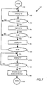
- Fig. 7 is an illustration, set forth by way of example and not limitation, of operation 64' of Fig. 6 .
- an operation 102 obtains another sample "X.”
- Decision operation 104 determines if this new sample "X" is equal to zero and, if so, loops back to operation 102 to take a new sample "X.” The loop of operations 102 and 104 continues until sample X is not equal to zero, at which time it is determined in an operation 106 that the beginning of a new burst-fired current cycle has been detected. The process 64' is then considered to be completed at 108.
- Figure 8 is an illustration, set forth by way of example and not limitation, of an operation 72' of Fig. 6 .
- Example operation 72' begins at 110 and then, in an operation 112, it sample (X) is stored in an array X(N).
- N Next, in an operation 114, it is determined whether N ⁇ 4. If so, stored samples X(N-1), X(N-2) and X(N-3) are each squared, summed and compared to zero in an operation 116. If they are equal to zero, it can be assumed that the burst-fired current cycle is in a current-off period. If operation 118 then determines that the current sample X is zero, it can be concluded in an operation 120 that the beginning of a new burst-fired current cycle is not detected.
- operation 118 determines that the current sample X is not equal to zero, after three previous zero samples, it can be concluded in an operation 122 that the beginning of a new burst-fired current cycle has been detected. The process of operation 71' is then concluded at 124.
- Fig. 9 helps illustrate the example processes of Figs. 6-8 .
- a number of sample points N are shown with respect to a burst-fired current 126.
- this low sample rate is for the purpose of illustration, where the actual sample rate will be at least an order of magnitude greater than the frequency of the burst-fired current 16.
- the sample rates are preferably at least in the kilohertz range.
- the AC current-on period is shown at t1 and the current-off period is shown as t2.
- Fig. 10 illustrates, a second non-limiting example method 128 for measuring RMS values of burst-fired currents.
- This method can be implemented by the aforementioned code segments stored in digital memory coupled to the processor 46 of Fig. 5 .
- the method can be implemented in other manners, e.g. by a state machine or by discrete logic.
- the method 128 begins at 130 with the start of a Background Process 132.
- the Background Process 132 operates continuously until interrupted by signals or "triggers" generated at regular intervals by, for example, the processor 46 internal clock. Should an interrupt trigger occur, Background Process 132 is suspended and an Interrupt Service Routine (ISR) or "Foreground Process" 134 is initiated. Once the Foreground Process 134 is completed, process control is returned to the Background Process 132 and the suspension of the Background Process is removed. The operation of the Background Process 132 will be discussed in greater detail with reference to Fig. 15 .
- the Background Process 132 will continue until interrupted, at which time it will be suspended.
- suspended it is meant that the state of the Background Process (including all necessary variables, parameters and states) will be maintained even though the process 132 will cease to execute.
- the Background Process 132 will again start to execute from the point where it was suspended.
- the Foreground Process 134 includes reading the A/D value from, for example, A/D converter 30 of Fig. 4 , in an operation 136.
- the variable Energy is calculated in operation 138 as the square of the A/D value determined in the previous operation.
- a Timing Process is initiated.
- the operation 140 of the Timing Process will be discussed in greater detail with reference to Figs. 11-13 .
- an Integration Process is initiated.
- the operation 142 of the Integration process will be discussed in greater detail with respect to Fig. 14 .
- Fig. 11 an operation 140', set forth by way of example but not limitation, of a Timing Process operation 140 of Fig. 10 is illustrated.
- the Timing Process begins at 144 and, in an operation 146, a variable "Counter” is incremented by 1 (as indicated by "Counter++).
- a variable "Counter” is incremented by 1 (as indicated by "Counter++).
- an operation 150 determines whether the variable Energy is greater than LowEnergy (which can be, for example, a predetermined constant). If not, an OffDutyCount++ Process is initiated in an operation 152.
- the OffDutyCount++ Process will be described in greater detail with reference to Fig. 13 . After operation 152 is completed, the Timing Process ends at 154.
- an operation 156 sets DutyState to ON.
- a decision operation 158 it is determined whether PeriodValidCount > 1. If not, a period has not been verified and an operation 160 increments PeriodValidCount by 1 (as indicated by PeriodValidCount++) and multiplies PendPeriodTime by 2.
- operation 162 (described above) is performed and the process is completed at 154.
- a decision operation 168 determines if Energy ⁇ LowEnergy. By way of non-limiting example, this can be determined when LowSignalCount > 4, where it is arbitrarily decided that an ON/OFF transition must be verified for over at least 5 interrupts. In other embodiments, other parameters may be used. In this example, if LowSignalCount is greater than 4, then an operation 170 sets LowSignalCount to zero, Off_Duty_Count to 5, On_Duty-Count to -4, DutyState to OFF, and OffDutyCount to 1 and the process is completed at 154.
- an operation 172 increments LowSignalCount (as indicated by LowSignalCount++).
- the combination of operations 168 and 172 signifies that there are four consecutive low signal counts to qualify a true "low signal” condition, in this non-limiting example.
- an OnDutyCount++ Process is initiated. OnDutyCount++ will be discussed in greater detail with respect to Fig. 12 . The process is then complete at 154.
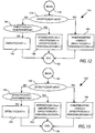
- FIG. 12 an operation 174', set forth by way of example but not limitation, of an OnDutyCount++ Process of Fig. 11 is illustrated.
- the OnDutyCount++ Process begins at 176 and, in an operation 178, it is determined whether OnDutyCount > MAX (which, again, can be a predetermined constant in some examples). If so, an operation 180 sets PendPeriodTime to DEFAULT, OnDutyCount to 1, and PeriodValidCount to 1. The process is then complete at 182. If, however, operation 178 determines that OnDutyCount ⁇ MAX, an operation 184 determines if OnDutyCount > PendPeriodTime.
- operation 186 increments OnDutyCount (as indicated by OnDutyCount++). If so, operation 188 sets IntegrationFlag, OnDutyCount, OffDutyCount and PeriodValidCount to 1. After performing either of operations 186 or 188 the process is completed at 182.
- an operation 152' set forth by way of example but not limitation, of an OffDutyCount++ Process of Fig. 11 is illustrated.
- the OffDutyCount++ Process begins at 190 and, in an operation 192, it is determined whether OffDutyCount > MAX. If so, an operation 194 sets PendPeriodTime to DEFAULT, OffDutyCount to 1, and PeriodValidCount to 1. The process is then complete at 196. If, however, operation 192 determines that OffDutyCount ⁇ MAX, an operation 198 determines if OffDutyCount > PendPeriodTime. If not, operation 200 increments OffDutyCount (as indicated by OffDutyCount++). If so, operation 202 sets IntegrationFlag, OnDutyCount, OffDutyCount and PeriodValidCount to 1. After performing either of operations 200 or 202 the process is completed at 196.
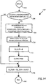
- FIG. 14 an operation 142', set forth by way of example but not limitation, of an Integration Process of Fig. 10 is illustrated.
- a copy of Sq_Sum e.g.
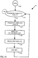
- FIG. 15 an operation 132', set forth by way of example but not limitation, of a Background Process of Fig. 10 is illustrated.
- the interrupt signals may occur every 1.2 milliseconds and the integration may be complete after 100 interrupts ( e.g . about every .12 seconds).
- the Background Process completes the RMS calculation and uses that as a PWM output for D/A purposes.
- a process for measuring RMS values of a burst-fired currents includes: a) initially sampling a burst-fired current signal; b) determining from the initial sampling a burst-fired current pattern; c) sampling the burst-fired current signals N times within a burst-fired current pattern to provide N samples, wherein the burst-fired current pattern includes an alternating current (AC) current-on period and an AC current-off period; and d) calculating an RMS value from the N samples.
- AC alternating current
- V RMS v 1 2 + v 2 2 + ... + v N 2 / N
- One or more calculated V RMS can be stored in digital memory, and an average V RMS value can be determined from a plurality of the stored V RMS values.
Landscapes
- Physics & Mathematics (AREA)
- General Physics & Mathematics (AREA)
- Measurement Of Current Or Voltage (AREA)
Claims (19)
- Appareil de mesure de paramètres RMS (quadratiques moyens) de dispositifs commandés par des courants à déclenchement en salve, comprenant :un capteur de courant (26) pour détecter un courant à déclenchement en salve ayant une sortie de signal;un convertisseur analogique-numérique (AN) (30) couplé à ladite sortie de signal dudit capteur de courant (26) ;un processeur numérique (46) couplé à une sortie dudit convertisseur AN (30) ; etune mémoire numérique (48, 50, 52) couplée audit processeur numérique (46) incluant des segments de code exécutables sur ledit processeur numérique (46) pour :a) échantillonner ladite sortie dudit convertisseur AN (30) ;b) détecter à partir dudit échantillonnage un modèle de courant à déclenchement en salve, dans lequel ledit modèle de courant à déclenchement en salve est détecté par détermination d'une pluralité d'échantillons à l'intérieur de périodes sans courant de courant alternatif (CA) dudit modèle de courant à déclenchement en salve suivis par un échantillon dans des périodes avec courant de courant alternatif (CA) dudit modèle de courant à déclenchement en salve;c) en réponse à la détection dudit échantillon à l'intérieur d'une période avec courant de CA dudit modèle de courant à déclenchement en salve, échantillonner ladite sortie dudit convertisseur AN (30) N fois à l'intérieur dudit modèle de courant à déclenchement en salve pour acquérir N échantillons; etd) calculer une valeur de paramètre RMS à partir desdits N échantillons acquis.
- Appareil de mesure de paramètres RMS de dispositifs commandés par des courants à déclenchement en salve selon la revendication 1, comprenant en outre un convertisseur numérique-analogique (NA) (34) ayant une entrée couplée audit processeur numérique (46).
- Appareil de mesure de paramètres RMS de dispositifs commandés par des courants à déclenchement en salve selon la revendication 2, comprenant en outre un amplificateur ayant une entrée couplée à une sortie dudit convertisseur NA (34).
- Appareil de mesure de paramètres RMS de dispositifs commandés par des courants à déclenchement en salve selon la revendication 3, dans lequel une sortie dudit amplificateur est compatible avec une norme 4-20 mA.
- Appareil de mesure de paramètres RMS de dispositifs commandés par des courants à déclenchement en salve selon la revendication 1, comprenant en outre un conditionneur de signaux (28) couplant ledit capteur de courant (26) audit convertisseur AN (30).
- Appareil de mesure de paramètres RMS de dispositifs commandés par des courants à déclenchement en salve selon la revendication 1, dans lequel ledit capteur de courant (26) est un capteur de courant inductif (26).
- Appareil de mesure de paramètres RMS de dispositifs commandés par des courants à déclenchement en salve selon la revendication 1, dans lequel ledit modèle de courant à déclenchement en salve comprend un cycle de courants à déclenchement en salve.
- Appareil de mesure de paramètres RMS de dispositifs commandés par des courants à déclenchement en salve selon la revendication 7, dans lequel ledit modèle de courant à déclenchement en salve comprend une pluralité de cycles de courants à déclenchement en salve.
- Appareil de mesure de paramètres RMS de dispositifs commandés par des courants à déclenchement en salve selon la revendication 1, dans lequel lesdites périodes avec courant CA comprennent au moins un cycle CA.
- Appareil de mesure de paramètres RMS de dispositifs commandés par des courants à déclenchement en salve selon la revendication 4, dans lequel lesdites périodes sans courant AC comprennent une période à courant nul.
- Appareil de mesure de paramètres RMS de dispositifs commandés par des courants à déclenchement en salve selon la revendication 1, dans lequel les N échantillons acquis sont N échantillons de niveau de tension comprenant {v1, v2, ..., vN} et dans lequel la valeur de paramètre RMS est une valeur de tension RMS, VRMS, et est calculée comme suit :

- Appareil de mesure de paramètres RMS de dispositifs commandés par des courants à déclenchement en salve selon la revendication 11, comprenant en outre le stockage de VRMS dans la mémoire numérique (48, 50, 52).
- Appareil de mesure de paramètres RMS de dispositifs commandés par des courants à déclenchement en salve selon la revendication 12, comprenant en outre le calcul et le stockage de multiples valeurs VRMS dans la mémoire numérique (48, 50, 52).
- Appareil de mesure de paramètres RMS de dispositifs commandés par des courants à déclenchement en salve selon la revendication 13, comprenant en outre le développement d'une valeur VRMS moyenne à partir d'une pluralité desdites valeurs VRMS stockées.
- Procédé de mesure de paramètres RMS de dispositifs commandés par des courants à déclenchement en salve, comprenant :a) l'échantillonnage d'un signal de courant à déclenchement en salve;b) la détection à partir dudit échantillonnage d'un modèle de courant à déclenchement en salve, dans lequel ledit modèle de courant à déclenchement en salve est détecté par détermination d'une pluralité d'échantillons à l'intérieur de périodes sans courant alternatif de courant alternatif (CA) dudit signal de courant à déclenchement en salve suivi par un échantillon à l'intérieur de périodes avec courant de courant alternatif (CA) dudit signal courant à déclenchement en salve;c) en réponse à la détection dudit échantillon à l'intérieur d'une période avec courant de CA dudit modèle de courant à déclenchement en salve, l'échantillonnage dudit signal de courant à déclenchement en salve N fois à l'intérieur dudit modèle de courant à déclenchement en salve pour acquérir N échantillons; etd) le calcul d'une valeur de paramètre RMS à partir desdits N échantillons acquis.
- Procédé de mesure de paramètres RMS de dispositifs commandés par des courants à déclenchement en salve selon la revendication 15, dans lequel les N échantillons acquis sont N échantillons de niveau de tension comprenant {v1, v2, ..., vN} et dans lequel la valeur de paramètre RMS est une valeur de tension RMS, VRMS, et est calculée comme suit :

- Procédé de mesure de paramètres RMS de dispositifs commandés par des courants à déclenchement en salve selon la revendication 16, comprenant en outre le stockage de VRMS dans la mémoire numérique (48, 50, 52).
- Procédé de mesure de paramètres RMS de dispositifs commandés par des courants à déclenchement en salve selon la revendication 17, comprenant en outre le calcul et le stockage de multiples valeurs VRMS dans la mémoire numérique (48, 50, 52).
- Procédé de mesure de paramètres RMS de dispositifs commandés par des courants à déclenchement en salve selon la revendication 18, comprenant en outre le développement d'une valeur VRMS moyenne à partir d'une pluralité desdites valeurs VRMS stockées.
Applications Claiming Priority (2)
| Application Number | Priority Date | Filing Date | Title |
|---|---|---|---|
| US13/784,702 US8589101B1 (en) | 2013-03-04 | 2013-03-04 | Method and apparatus for measuring RMS values of burst-fired currents |
| PCT/US2014/019639 WO2014137837A1 (fr) | 2013-03-04 | 2014-02-28 | Procédé et appareil de mesure de valeurs quadratiques moyennes (rms) de courants à déclenchement en salve |
Publications (3)
| Publication Number | Publication Date |
|---|---|
| EP2965097A1 EP2965097A1 (fr) | 2016-01-13 |
| EP2965097A4 EP2965097A4 (fr) | 2017-01-11 |
| EP2965097B1 true EP2965097B1 (fr) | 2018-05-16 |
Family
ID=49555850
Family Applications (1)
| Application Number | Title | Priority Date | Filing Date |
|---|---|---|---|
| EP14759463.4A Active EP2965097B1 (fr) | 2013-03-04 | 2014-02-28 | Procédé et appareil de mesure de valeurs quadratiques moyennes (rms) de courants à déclenchement en salve |
Country Status (4)
| Country | Link |
|---|---|
| US (1) | US8589101B1 (fr) |
| EP (1) | EP2965097B1 (fr) |
| CA (1) | CA2902958C (fr) |
| WO (1) | WO2014137837A1 (fr) |
Family Cites Families (21)
| Publication number | Priority date | Publication date | Assignee | Title |
|---|---|---|---|---|
| US4721906A (en) * | 1985-08-06 | 1988-01-26 | Duffers Scientific, Inc. | One step RMS system |
| EP0256183B1 (fr) * | 1986-08-15 | 1994-07-06 | Dynamic Systems Inc. | Mesure de la valeur efficace par échantillonnage du taux de variation du courant |
| JP3203015B2 (ja) * | 1991-09-02 | 2001-08-27 | 三洋電機株式会社 | 電源装置 |
| US5497332A (en) * | 1993-10-01 | 1996-03-05 | Automatic Terminal Information Systems, Inc. | Method and apparatus for metering and monitoring AC generators |
| US5473240A (en) * | 1993-12-30 | 1995-12-05 | Whirlpool Corporation | Motor control using third harmonic stator voltage signal |
| US5422570A (en) * | 1993-12-30 | 1995-06-06 | Whirlpool Corporation | Speed sensing for the third harmonic stator voltage signal |
| US5481166A (en) * | 1993-12-30 | 1996-01-02 | Whirlpool Corporation | Motor control for brushless permanent magnet using only three wires |
| US5345156A (en) * | 1993-12-30 | 1994-09-06 | Whirlpool Corporation | Control for high speed operation of brushless permanent magnet motor |
| US5473241A (en) * | 1994-07-26 | 1995-12-05 | Allen-Bradley Company, Inc. | Method and apparatus for RMS measurements in induction motor without sampling |
| US5671635A (en) * | 1994-11-14 | 1997-09-30 | Westinghouse Electric Corporation | Method and apparatus for monitoring of spring pack displacement of a motor-operated valve |
| US5906432A (en) * | 1997-09-19 | 1999-05-25 | American Ingredients Company | Dough mixer apparatus for laboratory testing of the development of a dough sample |
| DE19822127A1 (de) * | 1998-05-07 | 1999-11-11 | Siemens Ag | Verfahren und Schaltungsanordnung zur Stromerfassung |
| US6516279B1 (en) | 2000-05-18 | 2003-02-04 | Rockwell Automation Technologies, Inc. | Method and apparatus for calculating RMS value |
| US7007179B2 (en) * | 2001-02-08 | 2006-02-28 | Honeywell International Inc. | Electric load management center |
| US6566855B1 (en) | 2001-04-20 | 2003-05-20 | Neilsen-Kuljian, Inc. | Current sensor with frequency output |
| US7064290B2 (en) | 2003-09-08 | 2006-06-20 | Lincoln Global, Inc. | Electric arc welder and method for controlling the welding process of the welder |
| JP2006010508A (ja) * | 2004-06-25 | 2006-01-12 | Konica Minolta Sensing Inc | マルチアングル測色計 |
| US9134348B2 (en) * | 2009-04-16 | 2015-09-15 | Panoramic Power Ltd. | Distributed electricity metering system |
| FR2952483B1 (fr) * | 2009-11-06 | 2012-12-07 | Mge Ups Systems | Dispositif convertisseur et alimentation sans interruption equipee d'un tel dispositif. |
| JP5565670B2 (ja) * | 2010-02-10 | 2014-08-06 | 国立大学法人 名古屋工業大学 | 交流電力調整装置 |
| US8928184B2 (en) * | 2010-10-15 | 2015-01-06 | Echola Systems, Llc. | Reliable low-cost hybrid switch module for switched power distribution systems |
-
2013
- 2013-03-04 US US13/784,702 patent/US8589101B1/en active Active
-
2014
- 2014-02-28 EP EP14759463.4A patent/EP2965097B1/fr active Active
- 2014-02-28 WO PCT/US2014/019639 patent/WO2014137837A1/fr not_active Ceased
- 2014-02-28 CA CA2902958A patent/CA2902958C/fr active Active
Non-Patent Citations (1)
| Title |
|---|
| None * |
Also Published As
| Publication number | Publication date |
|---|---|
| US8589101B1 (en) | 2013-11-19 |
| CA2902958C (fr) | 2020-12-01 |
| CA2902958A1 (fr) | 2014-09-12 |
| EP2965097A1 (fr) | 2016-01-13 |
| EP2965097A4 (fr) | 2017-01-11 |
| WO2014137837A1 (fr) | 2014-09-12 |
Similar Documents
| Publication | Publication Date | Title |
|---|---|---|
| CN101490573B (zh) | 高精度原位电阻测量方法 | |
| CN104969666B (zh) | Rf脉冲发生与rf计量、处理和控制的同步 | |
| EP0518244B1 (fr) | Appareil de mesure d'un courant électrique pour un dispositif de commande à l'état solide de moteur | |
| JP6210938B2 (ja) | 非接触型電圧検出装置 | |
| US20220365143A1 (en) | Circuit and method for monitoring a dc link capacitor | |
| JP2011167061A5 (fr) | ||
| EP2938159A1 (fr) | Appareil de rouleau chauffé par induction | |
| CA1103336A (fr) | Controleur d'alimentation pour charges multiples avec processeur travaillant en temps partage | |
| CN109324347A (zh) | 电磁炉的检锅方法及装置 | |
| EP2062347B1 (fr) | Procede et dispositif de reduction de l'influence d'une composante continue dans un courant de charge d'un moteur asynchrone triphase | |
| US8589101B1 (en) | Method and apparatus for measuring RMS values of burst-fired currents | |
| EP2940482B1 (fr) | Système et procédé de mesure de la puissance active dans une charge sans une tension de charge | |
| TW201805648A (zh) | 控制器的輸出控制方法 | |
| US9584009B2 (en) | Line current reference generator | |
| EP3839522B1 (fr) | Compensation harmonique pour la mesure de courants | |
| JP5877261B1 (ja) | 電磁流量計の励磁コイル短絡判定方法 | |
| KR102892138B1 (ko) | 소결 장치용 전원 공급 시스템 및 이의 제어 방법 | |
| JP5352936B2 (ja) | 電力調整器 | |
| EP4682551A1 (fr) | Procédé, programme et dispositif | |
| RU2718597C1 (ru) | Способ мониторинга температуры обмотки электромагнита и устройство для его осуществления | |
| RU2042177C1 (ru) | Устройство для регулирования электрической мощности переменного тока | |
| CN103078367B (zh) | 一种限制脉冲放电的输出功率的方法及电路 | |
| WO2012157117A1 (fr) | Régulateur d'alimentation en courant alternatif | |
| KR101525779B1 (ko) | 모터의 전류 측정 장치 및 그를 이용한 전류 측정 방법 | |
| RU2245236C2 (ru) | Цифровой дозатор электроэнергии для точечной сварки |
Legal Events
| Date | Code | Title | Description |
|---|---|---|---|
| PUAI | Public reference made under article 153(3) epc to a published international application that has entered the european phase |
Free format text: ORIGINAL CODE: 0009012 |
|
| 17P | Request for examination filed |
Effective date: 20150917 |
|
| AK | Designated contracting states |
Kind code of ref document: A1 Designated state(s): AL AT BE BG CH CY CZ DE DK EE ES FI FR GB GR HR HU IE IS IT LI LT LU LV MC MK MT NL NO PL PT RO RS SE SI SK SM TR |
|
| AX | Request for extension of the european patent |
Extension state: BA ME |
|
| DAX | Request for extension of the european patent (deleted) | ||
| A4 | Supplementary search report drawn up and despatched |
Effective date: 20161214 |
|
| RIC1 | Information provided on ipc code assigned before grant |
Ipc: G01R 19/25 20060101ALI20161208BHEP Ipc: G01R 19/02 20060101AFI20161208BHEP |
|
| GRAP | Despatch of communication of intention to grant a patent |
Free format text: ORIGINAL CODE: EPIDOSNIGR1 |
|
| STAA | Information on the status of an ep patent application or granted ep patent |
Free format text: STATUS: GRANT OF PATENT IS INTENDED |
|
| INTG | Intention to grant announced |
Effective date: 20171123 |
|
| GRAS | Grant fee paid |
Free format text: ORIGINAL CODE: EPIDOSNIGR3 |
|
| GRAA | (expected) grant |
Free format text: ORIGINAL CODE: 0009210 |
|
| STAA | Information on the status of an ep patent application or granted ep patent |
Free format text: STATUS: THE PATENT HAS BEEN GRANTED |
|
| AK | Designated contracting states |
Kind code of ref document: B1 Designated state(s): AL AT BE BG CH CY CZ DE DK EE ES FI FR GB GR HR HU IE IS IT LI LT LU LV MC MK MT NL NO PL PT RO RS SE SI SK SM TR |
|
| REG | Reference to a national code |
Ref country code: GB Ref legal event code: FG4D |
|
| REG | Reference to a national code |
Ref country code: CH Ref legal event code: EP |
|
| REG | Reference to a national code |
Ref country code: IE Ref legal event code: FG4D |
|
| REG | Reference to a national code |
Ref country code: DE Ref legal event code: R096 Ref document number: 602014025596 Country of ref document: DE |
|
| REG | Reference to a national code |
Ref country code: AT Ref legal event code: REF Ref document number: 1000058 Country of ref document: AT Kind code of ref document: T Effective date: 20180615 |
|
| REG | Reference to a national code |
Ref country code: NL Ref legal event code: MP Effective date: 20180516 |
|
| REG | Reference to a national code |
Ref country code: LT Ref legal event code: MG4D |
|
| PG25 | Lapsed in a contracting state [announced via postgrant information from national office to epo] |
Ref country code: BG Free format text: LAPSE BECAUSE OF FAILURE TO SUBMIT A TRANSLATION OF THE DESCRIPTION OR TO PAY THE FEE WITHIN THE PRESCRIBED TIME-LIMIT Effective date: 20180816 Ref country code: FI Free format text: LAPSE BECAUSE OF FAILURE TO SUBMIT A TRANSLATION OF THE DESCRIPTION OR TO PAY THE FEE WITHIN THE PRESCRIBED TIME-LIMIT Effective date: 20180516 Ref country code: NO Free format text: LAPSE BECAUSE OF FAILURE TO SUBMIT A TRANSLATION OF THE DESCRIPTION OR TO PAY THE FEE WITHIN THE PRESCRIBED TIME-LIMIT Effective date: 20180816 Ref country code: SE Free format text: LAPSE BECAUSE OF FAILURE TO SUBMIT A TRANSLATION OF THE DESCRIPTION OR TO PAY THE FEE WITHIN THE PRESCRIBED TIME-LIMIT Effective date: 20180516 Ref country code: LT Free format text: LAPSE BECAUSE OF FAILURE TO SUBMIT A TRANSLATION OF THE DESCRIPTION OR TO PAY THE FEE WITHIN THE PRESCRIBED TIME-LIMIT Effective date: 20180516 Ref country code: ES Free format text: LAPSE BECAUSE OF FAILURE TO SUBMIT A TRANSLATION OF THE DESCRIPTION OR TO PAY THE FEE WITHIN THE PRESCRIBED TIME-LIMIT Effective date: 20180516 |
|
| PG25 | Lapsed in a contracting state [announced via postgrant information from national office to epo] |
Ref country code: HR Free format text: LAPSE BECAUSE OF FAILURE TO SUBMIT A TRANSLATION OF THE DESCRIPTION OR TO PAY THE FEE WITHIN THE PRESCRIBED TIME-LIMIT Effective date: 20180516 Ref country code: RS Free format text: LAPSE BECAUSE OF FAILURE TO SUBMIT A TRANSLATION OF THE DESCRIPTION OR TO PAY THE FEE WITHIN THE PRESCRIBED TIME-LIMIT Effective date: 20180516 Ref country code: NL Free format text: LAPSE BECAUSE OF FAILURE TO SUBMIT A TRANSLATION OF THE DESCRIPTION OR TO PAY THE FEE WITHIN THE PRESCRIBED TIME-LIMIT Effective date: 20180516 Ref country code: GR Free format text: LAPSE BECAUSE OF FAILURE TO SUBMIT A TRANSLATION OF THE DESCRIPTION OR TO PAY THE FEE WITHIN THE PRESCRIBED TIME-LIMIT Effective date: 20180817 Ref country code: LV Free format text: LAPSE BECAUSE OF FAILURE TO SUBMIT A TRANSLATION OF THE DESCRIPTION OR TO PAY THE FEE WITHIN THE PRESCRIBED TIME-LIMIT Effective date: 20180516 |
|
| REG | Reference to a national code |
Ref country code: AT Ref legal event code: MK05 Ref document number: 1000058 Country of ref document: AT Kind code of ref document: T Effective date: 20180516 |
|
| PG25 | Lapsed in a contracting state [announced via postgrant information from national office to epo] |
Ref country code: SK Free format text: LAPSE BECAUSE OF FAILURE TO SUBMIT A TRANSLATION OF THE DESCRIPTION OR TO PAY THE FEE WITHIN THE PRESCRIBED TIME-LIMIT Effective date: 20180516 Ref country code: RO Free format text: LAPSE BECAUSE OF FAILURE TO SUBMIT A TRANSLATION OF THE DESCRIPTION OR TO PAY THE FEE WITHIN THE PRESCRIBED TIME-LIMIT Effective date: 20180516 Ref country code: CZ Free format text: LAPSE BECAUSE OF FAILURE TO SUBMIT A TRANSLATION OF THE DESCRIPTION OR TO PAY THE FEE WITHIN THE PRESCRIBED TIME-LIMIT Effective date: 20180516 Ref country code: DK Free format text: LAPSE BECAUSE OF FAILURE TO SUBMIT A TRANSLATION OF THE DESCRIPTION OR TO PAY THE FEE WITHIN THE PRESCRIBED TIME-LIMIT Effective date: 20180516 Ref country code: AT Free format text: LAPSE BECAUSE OF FAILURE TO SUBMIT A TRANSLATION OF THE DESCRIPTION OR TO PAY THE FEE WITHIN THE PRESCRIBED TIME-LIMIT Effective date: 20180516 Ref country code: EE Free format text: LAPSE BECAUSE OF FAILURE TO SUBMIT A TRANSLATION OF THE DESCRIPTION OR TO PAY THE FEE WITHIN THE PRESCRIBED TIME-LIMIT Effective date: 20180516 Ref country code: PL Free format text: LAPSE BECAUSE OF FAILURE TO SUBMIT A TRANSLATION OF THE DESCRIPTION OR TO PAY THE FEE WITHIN THE PRESCRIBED TIME-LIMIT Effective date: 20180516 |
|
| REG | Reference to a national code |
Ref country code: DE Ref legal event code: R097 Ref document number: 602014025596 Country of ref document: DE |
|
| PG25 | Lapsed in a contracting state [announced via postgrant information from national office to epo] |
Ref country code: IT Free format text: LAPSE BECAUSE OF FAILURE TO SUBMIT A TRANSLATION OF THE DESCRIPTION OR TO PAY THE FEE WITHIN THE PRESCRIBED TIME-LIMIT Effective date: 20180516 Ref country code: SM Free format text: LAPSE BECAUSE OF FAILURE TO SUBMIT A TRANSLATION OF THE DESCRIPTION OR TO PAY THE FEE WITHIN THE PRESCRIBED TIME-LIMIT Effective date: 20180516 |
|
| PLBE | No opposition filed within time limit |
Free format text: ORIGINAL CODE: 0009261 |
|
| STAA | Information on the status of an ep patent application or granted ep patent |
Free format text: STATUS: NO OPPOSITION FILED WITHIN TIME LIMIT |
|
| 26N | No opposition filed |
Effective date: 20190219 |
|
| PG25 | Lapsed in a contracting state [announced via postgrant information from national office to epo] |
Ref country code: SI Free format text: LAPSE BECAUSE OF FAILURE TO SUBMIT A TRANSLATION OF THE DESCRIPTION OR TO PAY THE FEE WITHIN THE PRESCRIBED TIME-LIMIT Effective date: 20180516 |
|
| REG | Reference to a national code |
Ref country code: CH Ref legal event code: PL |
|
| PG25 | Lapsed in a contracting state [announced via postgrant information from national office to epo] |
Ref country code: LU Free format text: LAPSE BECAUSE OF NON-PAYMENT OF DUE FEES Effective date: 20190228 Ref country code: MC Free format text: LAPSE BECAUSE OF FAILURE TO SUBMIT A TRANSLATION OF THE DESCRIPTION OR TO PAY THE FEE WITHIN THE PRESCRIBED TIME-LIMIT Effective date: 20180516 |
|
| REG | Reference to a national code |
Ref country code: BE Ref legal event code: MM Effective date: 20190228 |
|
| REG | Reference to a national code |
Ref country code: IE Ref legal event code: MM4A |
|
| PG25 | Lapsed in a contracting state [announced via postgrant information from national office to epo] |
Ref country code: AL Free format text: LAPSE BECAUSE OF FAILURE TO SUBMIT A TRANSLATION OF THE DESCRIPTION OR TO PAY THE FEE WITHIN THE PRESCRIBED TIME-LIMIT Effective date: 20180516 |
|
| PG25 | Lapsed in a contracting state [announced via postgrant information from national office to epo] |
Ref country code: LI Free format text: LAPSE BECAUSE OF NON-PAYMENT OF DUE FEES Effective date: 20190228 Ref country code: CH Free format text: LAPSE BECAUSE OF NON-PAYMENT OF DUE FEES Effective date: 20190228 |
|
| PG25 | Lapsed in a contracting state [announced via postgrant information from national office to epo] |
Ref country code: IE Free format text: LAPSE BECAUSE OF NON-PAYMENT OF DUE FEES Effective date: 20190228 |
|
| PG25 | Lapsed in a contracting state [announced via postgrant information from national office to epo] |
Ref country code: BE Free format text: LAPSE BECAUSE OF NON-PAYMENT OF DUE FEES Effective date: 20190228 |
|
| PG25 | Lapsed in a contracting state [announced via postgrant information from national office to epo] |
Ref country code: TR Free format text: LAPSE BECAUSE OF FAILURE TO SUBMIT A TRANSLATION OF THE DESCRIPTION OR TO PAY THE FEE WITHIN THE PRESCRIBED TIME-LIMIT Effective date: 20180516 |
|
| PG25 | Lapsed in a contracting state [announced via postgrant information from national office to epo] |
Ref country code: MT Free format text: LAPSE BECAUSE OF NON-PAYMENT OF DUE FEES Effective date: 20190228 Ref country code: PT Free format text: LAPSE BECAUSE OF FAILURE TO SUBMIT A TRANSLATION OF THE DESCRIPTION OR TO PAY THE FEE WITHIN THE PRESCRIBED TIME-LIMIT Effective date: 20180917 |
|
| PG25 | Lapsed in a contracting state [announced via postgrant information from national office to epo] |
Ref country code: CY Free format text: LAPSE BECAUSE OF FAILURE TO SUBMIT A TRANSLATION OF THE DESCRIPTION OR TO PAY THE FEE WITHIN THE PRESCRIBED TIME-LIMIT Effective date: 20180516 |
|
| PG25 | Lapsed in a contracting state [announced via postgrant information from national office to epo] |
Ref country code: IS Free format text: LAPSE BECAUSE OF FAILURE TO SUBMIT A TRANSLATION OF THE DESCRIPTION OR TO PAY THE FEE WITHIN THE PRESCRIBED TIME-LIMIT Effective date: 20180916 |
|
| PG25 | Lapsed in a contracting state [announced via postgrant information from national office to epo] |
Ref country code: HU Free format text: LAPSE BECAUSE OF FAILURE TO SUBMIT A TRANSLATION OF THE DESCRIPTION OR TO PAY THE FEE WITHIN THE PRESCRIBED TIME-LIMIT; INVALID AB INITIO Effective date: 20140228 |
|
| PG25 | Lapsed in a contracting state [announced via postgrant information from national office to epo] |
Ref country code: MK Free format text: LAPSE BECAUSE OF FAILURE TO SUBMIT A TRANSLATION OF THE DESCRIPTION OR TO PAY THE FEE WITHIN THE PRESCRIBED TIME-LIMIT Effective date: 20180516 |
|
| PGFP | Annual fee paid to national office [announced via postgrant information from national office to epo] |
Ref country code: GB Payment date: 20260219 Year of fee payment: 13 |
|
| PGFP | Annual fee paid to national office [announced via postgrant information from national office to epo] |
Ref country code: DE Payment date: 20260226 Year of fee payment: 13 |
|
| PGFP | Annual fee paid to national office [announced via postgrant information from national office to epo] |
Ref country code: FR Payment date: 20260219 Year of fee payment: 13 |