EP2965341B1 - Filament cathodique de tube à rayons x - Google Patents
Filament cathodique de tube à rayons x Download PDFInfo
- Publication number
- EP2965341B1 EP2965341B1 EP14719180.3A EP14719180A EP2965341B1 EP 2965341 B1 EP2965341 B1 EP 2965341B1 EP 14719180 A EP14719180 A EP 14719180A EP 2965341 B1 EP2965341 B1 EP 2965341B1
- Authority
- EP
- European Patent Office
- Prior art keywords
- wire end
- filament
- end section
- receptacle
- section
- Prior art date
- Legal status (The legal status is an assumption and is not a legal conclusion. Google has not performed a legal analysis and makes no representation as to the accuracy of the status listed.)
- Active
Links
Images

Classifications
-
- H—ELECTRICITY
- H01—ELECTRIC ELEMENTS
- H01J—ELECTRIC DISCHARGE TUBES OR DISCHARGE LAMPS
- H01J1/00—Details of electrodes, of magnetic control means, of screens, or of the mounting or spacing thereof, common to two or more basic types of discharge tubes or lamps
- H01J1/02—Main electrodes
- H01J1/13—Solid thermionic cathodes
- H01J1/15—Cathodes heated directly by an electric current
- H01J1/18—Supports; Vibration-damping arrangements
-
- B—PERFORMING OPERATIONS; TRANSPORTING
- B23—MACHINE TOOLS; METAL-WORKING NOT OTHERWISE PROVIDED FOR
- B23K—SOLDERING OR UNSOLDERING; WELDING; CLADDING OR PLATING BY SOLDERING OR WELDING; CUTTING BY APPLYING HEAT LOCALLY, e.g. FLAME CUTTING; WORKING BY LASER BEAM
- B23K35/00—Rods, electrodes, materials, or media, for use in soldering, welding, or cutting
- B23K35/22—Rods, electrodes, materials, or media, for use in soldering, welding, or cutting characterised by the composition or nature of the material
- B23K35/24—Selection of soldering or welding materials proper
- B23K35/32—Selection of soldering or welding materials proper with the principal constituent melting at more than 1550°C
-
- H—ELECTRICITY
- H01—ELECTRIC ELEMENTS
- H01J—ELECTRIC DISCHARGE TUBES OR DISCHARGE LAMPS
- H01J35/00—X-ray tubes
- H01J35/02—Details
- H01J35/04—Electrodes ; Mutual position thereof; Constructional adaptations therefor
- H01J35/06—Cathodes
- H01J35/064—Details of the emitter, e.g. material or structure
-
- H—ELECTRICITY
- H01—ELECTRIC ELEMENTS
- H01J—ELECTRIC DISCHARGE TUBES OR DISCHARGE LAMPS
- H01J2235/00—X-ray tubes
- H01J2235/06—Cathode assembly
Definitions
- the present invention relates to a filament, in particular an X-ray cathode filament, which has at least one emitter or heating filament made of a W-based material with protruding wire end sections and holding pins, each associated with the wire end sections, made of a high-melting metal or a high-melting metal alloy for fixing and electrical contacting of the wire end sections.
- At least one mounting pin has a receptacle on the end face, in which a wire end section is received and is integrally connected to the mounting pin within the receptacle.
- the invention further relates to a manufacturing method for such a filament.
- Such X-ray cathode filaments are used in X-ray tubes for the emission of electrons. They usually have a heating filament (e.g. a wire coil with protruding wire end sections) that is supplied with electrical current in use. As a result, electrons are either emitted directly from an electron-emitting section of the heating filament (in the case of a directly heated X-ray cathode filament) or from a component heated by the heating filament (in the case of indirect heating). The emitted electrons are accelerated in the form of a focused electron beam onto a corresponding X-ray anode. A large part of the energy of the electron beam is converted into heat in the X-ray anode, while a small part is emitted as X-ray radiation.
- a heating filament e.g. a wire coil with protruding wire end sections
- electrons are either emitted directly from an electron-emitting section of the heating filament (in the case of a directly heated X-ray catho
- a directly heated cathode in which a cathode filament made of tungsten is attached to cathode struts made of high-melting metal by means of point-supplied heat, the attachment being carried out using platinum as a solder.
- a cathode arrangement is known in which the wire end portions of the heating filament are fixed by means of spot welding to corresponding holding pins provided with an axial gap. The two mounting feet of the mounting pins obtained through the axial gap are designed such that one foot remains unchanged, while the other is slightly bent by the spot welding process.
- a method for connecting a high-melting component formed from a thin plate or a thin wire by means of laser welding to a base material made of iron, nickel or the like.
- the laser beam is directed from the side of the base material onto the base material and a material flow of the molten base material is generated, which envelops the thin plate or the thin wire. That in the JP 58-90389 A
- the method described is particularly suitable for connecting a heating coil of an electron tube with a corresponding holder.
- the heating filament is usually made of a W-based material and the holding pins are usually made of a high-melting metal or a high-melting metal alloy (such as a Mo-based material).
- a high-melting metal or a high-melting metal alloy such as a Mo-based material.
- the requirement here is that the heating filament and the mounting pins are connected to one another in a mechanically stable manner and good electrical contact is ensured. This connection must withstand the high temperatures that occur during use.
- a corresponding problem generally exists with filaments which have an emitter filament or heating filament made from a W-based material and corresponding holding pins. Such filaments are used, for example, in lighting applications, for high-temperature heating structures, for example for MOCVD applications (metal-organic chemical vapor deposition), heating systems, etc., and as evaporator filaments for coating applications.
- the object of the present invention is to provide a filament, in particular an X-ray cathode filament, and a method for producing a filament, in particular an X-ray cathode filament, in which the connection between the emitter or heating filament and at least one holding pin is designed such that it permanently ensures a mechanically stable mounting and good electrical contacting even at the high temperatures that occur during use.
- a filament in particular an X-ray cathode filament, according to claim 1 and by a method for producing a filament, in particular an X-ray cathode filament, according to claim 11.
- Advantageous developments of the invention are specified in the subclaims.
- Such filaments are used, for example, in lighting applications, for high-temperature heating structures, for example for MOCVD applications (metal-organic chemical vapor deposition), heating systems, etc., and as evaporator filaments for coating applications.
- the filament in particular the X-ray cathode filament, has at least one emitter or heating filament (in the case of an X-ray cathode filament usually referred to as heating filament) made of a W-based material (W: tungsten), which protrudes wire end sections (also from the W -based material), and the wire end sections each have associated holding pins made of a high-melting metal or a high-melting metal alloy for fixing and electrical contacting of the wire end sections.
- At least one mounting pin has a receptacle on the end face, in which a wire end section is received and is integrally connected to the mounting pin within the receptacle.
- the integral connection is made using an additional material made of V (V: vanadium) or a V-based alloy, which is integrally connected to the wire end section and integrally connected to the mounting pin. All of the wire end sections of the at least one emitter or heating filament are preferably connected by means of such a material connection to corresponding mounting pins.
- V vanadium
- All of the wire end sections of the at least one emitter or heating filament are preferably connected by means of such a material connection to corresponding mounting pins.
- V or a V-based alloy as filler material, a relatively lower temperature is required to connect the wire end section to the mounting pin compared to a connection technique without using a filler material due to the comparatively low melting point of V (melting point: 1910 ° C of pure V) (compared to the melting temperatures of pure W, pure Mo and other high-melting metals that are suitable as material for the mounting pins).
- V shows good wetting of the emitter or heating filament made of W-based material and the mounting pins made of a high-melting metal or a high-melting metal alloy. This is especially true when the mounting pins are made of Mo or a Mo-based alloy.
- V Compared to the use of Pt (platinum) as filler material, V has the advantage that it generally does not form any intermetallic phases with the high-melting metals that are suitable as materials for the mounting pins and has good miscibility with them. This advantage exists in particular if the mounting pins are made of Mo or a Mo-based alloy. In contrast, Pt forms intermetallic phases with Mo, which can reduce the stability of the connection, particularly at high operating temperatures. In terms of high temperature stability, another advantage of V is that it has a higher melting point than Pt (1910 ° C for V compared to 1768 ° C for Pt) and that when mixed with Mo (due to diffusion effects and / or due to the formation of a melting alloy) a melting point increase occurs. Further advantages of V as filler material are that it has a lower vapor pressure compared to Pt (ie it is highly vacuum compatible), that there is sufficient availability as a raw material and that it has a significant cost advantage compared to Pt.
- X-ray cathode filaments are well known in the art and are used in X-ray tubes to emit electrons.
- X-ray cathode filaments of this type can be used in X-ray tubes of different types, such as, for example, in X-ray tubes for medical applications, in X-ray tubes for luggage scanning (for example at airports), in X-ray tubes for material testing, etc.
- W-based material reference is made in particular to pure tungsten or to a W alloy which consists of W at least 50% by weight. In particular, the W alloy consists of at least 90% by weight W.
- the heating filament is in particular designed as a directly heated heating filament, that is to say that it emits electrons directly when electrical current is supplied.
- the heating filament different cross-sections, cross-sections that may vary over the extension length, different geometries, in particular spiral geometries, etc.), such as flat heaters, wire filaments, etc., with the preferred embodiment being wire filament. If the heating filament has a coil, different coil geometries are possible.
- one and the same heating filament has two or more coils integrated into one another, as is the case, for example, with a wire wound with a first, small coil diameter, which is additionally wound in a coil shape with a second, large coil diameter is.
- the helix cross section varies along the helix axis.
- the X-ray cathode filament can also have two or more heating filaments, which then generally also each have separate wire end sections and separate holding pins.
- the wire end sections preferably protrude essentially perpendicular to the main direction of extension of the electron-emitting section.
- the electron-emitting section is designed as a helix, this main direction of extension corresponds to the helix axis. It is preferred that the wire end portions run parallel to each other.
- the protruding wire end sections serve for mechanical mounting and for electrical contacting of the heating filament. They have an elongated main direction of extension. They preferably have an essentially round cross section. Corresponding configurations are also possible here in the case of an emitter filament.
- “high-melting” refers to metals and metal alloys which have a melting point of 2. 2,000 ° C.
- the receptacle is designed in such a way that it extends from the end in the axial direction (of the relevant holding pin) to a predetermined depth in the respective holding pin.
- an overlap region of the receptacle with the corresponding wire end section is provided in the axial direction, and the relevant wire end section is surrounded on both sides by the receptacle with respect to at least one radial direction running perpendicular to the axial direction.
- the receptacle can be formed by a gap extending along the axial direction.
- the receptacle can be formed, for example, by a hole extending along the axial direction.
- a “filler material” is a material that is provided in addition to the material of the holding pin and the material of the emitter or heating filament (made of W-based material).
- V or a V-based alloy refers in particular to pure V or a V alloy which consists of at least 50% by weight of V. In particular, the V alloy consists of at least 90% by weight of V. It is preferred that pure V (with impurities and / or additives up to a maximum of 5% by weight) is used as the starting filler material (ie before it is melted to produce the connection). %).
- material from the holding pin and possibly also from the wire end section can be taken up, in particular dissolved, in the filler material.
- Material from the wire end section is not, or only to a very small extent, incorporated into the filler material due to its very high melting point.
- the wire end sections form part of the emitter or heating filament and are formed from one and the same W-based material.
- the entire emitter or heating filament is in one piece and made from one and the same material, i.e. it has no connection zones between two parts originally formed separately.
- the filler material is at least in sections in a melting phase.
- good wetting of the mounting pin and the wire end section by the filler material can be achieved.
- a melt phase is a phase that is obtained from a melt by solidification of the material in question.
- the presence of a melt phase can be identified by metallurgical testing methods.
- a melting phase has newly formed crystals during the solidification process. This microstructure, which is typical of a melting phase, can be distinguished by a person skilled in the art from the starting filler material present before the heating.
- a suitable metallurgical examination method for determining whether a melting phase is present is that a (typically axial) cross section is produced through the wire end section, the holding pin and the filler material, the surface obtained thereby embedded in a resin, ground, polished and with a scanning electron microscope (or alternatively with a light microscope) in the area of the filler material.
- the filler material is preferably in a melting phase at least in a contact area between the holding pin and the wire end section.
- a melting phase at least in a contact area between the holding pin and the wire end section.
- a resistance welding method in particular a resistance spot welding method
- a larger or complete one Melting of the starting filler material can be achieved if the entire arrangement (consisting of emitter or heating filament, starting filler material and at least one retaining pin) is heated to such high temperatures that the starting filler material melts to produce the integral connection.
- the starting filler material is locally heated and melted by means of a beam welding process, in particular by a laser welding process, in this variant too, a large-area or also in this variant complete melting of the starting filler material can be achieved.
- the filler material wets the wire end section over at least 75% of the circumference (of the wire end section) at least over an axial section of the wire end section arranged within the receptacle (axial: main direction of extension of the wire end section) and is at least in this area in a melting phase.
- a melting phase Such widespread wetting of the wire end section with the filler material present in a melting phase produces a stable hold and good electrical contact.
- Such wetting over a large area can be obtained in particular by melting the starting filler material introduced into the corresponding position within the receptacle at least in sections by means of a beam welding process (for example electron beam welding process, laser welding process).
- the axial section of the wire end section wetted over at least 75% of the circumference preferably has a length in the range of 0.2-1.5 mm. This area applies in particular to an axial overlap area between the wire end section and the receptacle, for example 2 mm in length.
- the mounting pins are made of Mo (Mo: molybdenum) or a Mo-based alloy. Due to its high melting point, Mo is generally well suited as a base material for the mounting pins. In combination with V as filler material, there is the additional advantage that Mo and V are soluble in one another across all compositions and do not form any intermetallic phases. The Mo dissolved due to diffusion effects and / or due to the formation of a melting alloy in the V additionally leads to an increase in the melting point of the filler material (compared to the starting filler material), which is advantageous in view of the high-temperature stability of the connection.
- Mo-based refers to an alloy that has ⁇ 50% by weight, in particular ⁇ 90% by weight, Mo. In the case of a Mo alloy, this contains in particular further metals or, to a small extent, non-metallic additives, such as oxides, and / or doping.
- the filler material is at least in sections in a melting phase and the melting phase forms a melting alloy which contains at least V and Mo as alloy metals.
- a melt alloy is understood to mean an alloy obtained by melting V and Mo and by mixing the same. Compared to solid-state diffusion, a more uniform mixing of V and Mo takes place when a melt alloy is formed.
- the filler material is completely in a melting phase and forms the melting alloy mentioned. This can be achieved in particular if - as explained above - a beam welding process (e.g.
- laser welding possibly also electron beam welding
- a "weld connection" according to the definition of "welding” is only present if the wire end section is also melted at least on a narrow edge zone thereof. Otherwise - that is, if only the starting filler and part of the mounting pin are melted become - it is a hybrid between welding and soldering.
- the melting alloy can also have further metallic and / or non-metallic components, depending on which materials are used for the starting filler material, the holding pin and for the wire end sections.
- the filler material obtained after heating should consist to the greatest extent of the material of the starting filler material, in which to a lesser extent material (in particular Mo) is released from the mounting pin, and in that if necessary, a significantly smaller proportion of material can also be released from the wire end section (for example due to diffusion effects or by melting of its edge zone).
- the wire end section is in the area of the exit point of the wire end section from the receptacle in a non-recrystallized structure.
- the entire section of the wire end section located within the receptacle is preferably in a non-recrystallized structure.
- Such a non-recrystallized structure of the wire end section is generally desirable due to its preferred properties (higher ductility).
- the wire end section can also be present in sections within the receptacle in a partially recrystallized structure.
- a non-recrystallized structure is usually set in the course of the manufacturing process of the emitter or heating filament by reshaping (in the case of a wire: drawing) and moderate annealing.
- the recrystallization proceeds with increasing temperature and with increasing heating time until a completely recrystallized structure is obtained. Accordingly, excessive and prolonged heating of the wire end sections in the course of the production of the integral connection should be avoided as far as possible.
- the non-recrystallized structure of the wire end section provided in accordance with this development can largely be retained, in particular when producing the integral connection, if a beam welding process, preferably a laser welding process, for melting the starting filler material (and possibly a part of the Bracket pin and possibly a narrow edge zone of the wire end portion) is used. This results in only local and relatively short-term heating, so that the non-recrystallized structure can largely be retained in the area of the wire end sections. Possibly.
- the recrystallization in the immediate vicinity of the point of impact of the welding beam (in particular the laser) can progress somewhat more strongly than in the surrounding areas. Due to the local energy input in a beam welding process, excessive heating of the heat-emitting and / or electron-emitting section of the emitter or heating filament can also be avoided.
- a forming structure is obtained by the forming step. As is known in the art, this has no clear grain boundaries surrounding individual crystal grains. It also has a large number of dislocations. A new grain formation then takes place within the framework of the recrystallization. This initially creates small crystals with clear, circumferential grain boundaries, which increase with increasing degree of recrystallization. The proportion of the forming structure is increasingly reduced until there is no or almost no forming structure left between the newly formed crystals when the structure is completely recrystallized.
- a structure that is not or only partially recrystallized can - as is known in the art - be recognized by powder metallurgical examination methods.
- a cross section is made through the wire end section (and possibly also through the surrounding filler material and holding pin) (in particular in the axial direction), the surface obtained in this way embedded in a resin, ground and polished (eg electropolished).
- a distinction between a non-recrystallized, a partially recrystallized and a completely recrystallized structure can usually be made by a person skilled in the art by examining the prepared samples in a scanning electron microscope.
- EBSD Electron Backscatter Diffraction; German: electron reflective diffraction
- ECCI Electron Channeling Contrast Imaging; German: electron channelization contrast imaging
- a partially recrystallized structure is understood to mean a structure in which crystal grains formed by new grain formation are surrounded by a reshaping structure and in which, with respect to a cross-sectional area through the partially recrystallized structure, these crystal grains have an area fraction in the range from 1-90 % form.
- the filler material is formed by at least one molded part that is present in sections in a melting phase, which extends within the receptacle over an axial longitudinal section of the wire end section and forms a guide for the wire end section within the receptacle along the axial longitudinal section, the integral connection only via a partial section of the axial longitudinal section is formed and the partial section is arranged within the receptacle axially spaced from the point at which the wire end section emerges from the guide (and, if appropriate, the receptacle).
- the molded part and the guide provided by the molded part extend to the point of exit of the wire end section from the receptacle.
- the filler material is preferably formed by exactly one molded part. Possibly. However, several molded parts, which are preferably lined up in the axial direction on the wire end section, can also be provided.
- the molded part In principle, different shapes are possible for the molded part, the shape being selected such that the molded part in question provides a guide for the wire end portion within the receptacle over an axial longitudinal section.
- the initial molded part (before the material connection is established) can be formed by an axially slotted sleeve, by a tubular sleeve, by at least two axially extending shells which are connected to one another via corresponding webs, etc., the use of a axially slotted sleeve is preferred.
- the initial molded part is melted, in particular in the region of the partial section, the original shape of the initial molded part being retained in the remaining sections.
- At least one axial section of the molded part is formed by a sleeve slotted along the axial direction, in which the wire end section is received.
- a slotted sleeve is used in particular as the starting molded part for the production of such an embodiment.
- the slotted sleeve (or alternatively a differently configured starting molded part) is pushed over the wire end section and the wire end section and the sleeve (or generally Output molding) are preferably positioned within the receptacle in such a way that the end of the sleeve (or generally of the starting molding) and the end of the receptacle are arranged flush to the side of the emitter or heating filament.
- the cohesive connection is preferably produced by supplying heat (for example via a beam welding process) in the area of the cohesive connection to be produced, axially spaced from the exit point of the wire end section from the sleeve (or generally the starting molded part) locally in this area the filler material (as well as any surrounding material of the mounting pin and possibly a narrow edge zone of the wire end section) is melted.
- a cohesive connection is established between the retaining pin and the wire end section, while in the remaining areas the filler material continues to be in the form of a slotted sleeve (or generally in the original shape of the starting material). Molding) is present and provides guidance of the wire end portion.
- the emitter or heating filament is formed by a continuous wire.
- the wire does not necessarily have to have a round cross-section (eg oval cross-section, flat cross-section, etc. possible). With a view to simple and inexpensive production, a round or substantially round cross section is preferred.
- the emitter or heating filament is formed by a wire helix with protruding wire end sections. Such training is advantageous in terms of simple and inexpensive manufacture. With the wire helix, different helix cross-sections of the winding are possible (e.g. triangular, shape of a lying D, circular, oval, etc.). Furthermore, the helix cross section can also vary along the helix axis.
- the receptacle is formed by a gap which begins at the end and which extends continuously in the radial direction and in the axial direction to a predetermined depth of the holding pin.
- the method according to the invention enables a reliable and reproducible production of the integral connection. Furthermore, the advantages explained above in relation to the filament according to the invention, in particular X-ray cathode filament, are achieved. In the method according to the invention, the variants and developments explained above in relation to the filament according to the invention, in particular X-ray cathode filament, can be implemented in a corresponding manner.
- the starting filler material refers to the material that is used in addition to that for the production of the integral connection Wire end portion is introduced into the receptacle and which is present before the step of heating.
- the material present after the heating step is then referred to as the filler material.
- the starting filler material there are different ways of introducing the starting filler material, such as the starting molded part surrounding at least one axial longitudinal section of the wire end section (axially slotted sleeve, tubular sleeve, at least two axially extending shells which are connected to one another via corresponding webs, etc.) , as a wire, as a plate or sheet, as a paste, as a powder, etc.
- step B) the steps of insertion (step B)) and heating (step C)) are carried out in parallel on a plurality of wire end sections and the associated mounting pins will.
- the “area of the connection to be made” comprises at least a partial section of the axial overlap area between the holding pin and the wire end section.
- the heating step such as, for example, heating the entire arrangement in an oven or a preferred, local supply of heat by means of a beam welding process.
- the heat is supplied locally in the area of the connection to be produced, as a result of which aging effects in the heat-radiating and / or electron-emitting area are avoided.
- the direct supply of heat preferably takes place exclusively or at least to a predominant extent to the starting filler material and / or to a section of the holding pin adjacent to the starting filler material, in the latter case the starting filler material being heated at least to a considerable extent by heat conduction.
- the direct supply of heat preferably takes place axially spaced from the exit point of the wire end section from the sleeve or generally from the starting molded part (for example by means of a beam welding process) in the area within the receptacle.
- the heat is preferably applied using a beam welding process.
- the step of heating is carried out by laser welding. This enables a particularly effective, locally limited Heating, whereby a brief supply of energy (laser pulse) is sufficient to melt the starting filler material.
- the step of heating is carried out without the holding pin and the wire end section being pressed against one another by a pressing force. In this way, deformation of the components and / or the introduction of mechanical stresses are avoided in comparison to a resistance welding process.
- material of the holding pin in particular Mo
- Mo is melted in the heating step and it forms a melting alloy with the material of the starting additional material.
- the advantages of increasing the melting point can be used. Possibly. a narrow edge zone of the wire end section can also be melted, so that a "welded connection" in the actual sense is then present.
- heat treatment stress relief annealing
- moderate temperatures i.e. significantly below the recrystallization temperature of the emitter or heating filament
- the heat treatment can be carried out, for example, in a temperature range from 800 ° C. to 1,000 ° C. over a period of 1 hour.
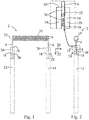
- the X-ray cathode filament 2 has a heating filament 4 formed as a wire filament with two protruding wire end sections 6, 8.
- the electron-emitting section of the heating filament 4 is designed as a wire coil 10, the wire end sections 6, 8 being formed by the protruding wire ends of the wire coil 10.
- the wire of the heating filament 4 is made of tungsten with appropriate high-temperature stabilizing dopants (such as potassium).
- a suitable material is, for example, tungsten doped with AKS, ie tungsten doped with aluminum, potassium and silicon.
- two mounting pins 12, 14 made of Mo and assigned to the two wire end sections 6, 8 are provided.
- the mounting pins 12, 14 are each provided with a gap 18 starting from the end face 16, which extends completely in the radial direction 20 through the respective mounting pin 12, 14 and which extends axially Direction 22 extends to a predetermined depth.
- the arrangement is such that the wire coil 10 defines a coil axis 23.
- the helix cross section is circular and constant over the course of the helix axis 23.
- the wire end sections 6, 8 protrude perpendicularly from the helix axis 23 and run parallel to one another.
- the support pins 12, 14 are also aligned with their axial direction 22 parallel to the wire end sections 6, 8.
- the respective mounting pin 12 or 14 in the relevant end section is divided into two mounting feet 24, 26, each of which extends along the axial direction 22.
- the bracket foot 24 facing the viewer is shown cut off in order to show the position of the wire end sections 6, 8.
- the gaps 18 each form a receptacle for the wire end sections 6, 8.
- the wire end sections 6, 8 are arranged essentially centrally in the receptacles of the holding pins 12, 14.
- the wire end sections 6, 8 do not extend as far as the gap base 28, but are somewhat spaced from it.
- the wire end sections 6, 8 are connected to the respective mounting pin 12 or 14 by a material connection via an additional material 30.
- filler material 30 is completely in the form of a melting phase. It is formed by a melting alloy of V, Mo and W, which contains a significantly higher proportion of V and only a very small proportion of W (the composition varies over the range of the melting alloy, ie it is graded).
- V, Mo and W which contains a significantly higher proportion of V and only a very small proportion of W (the composition varies over the range of the melting alloy, ie it is graded).
- the filler material 30 wets the wire end section 8 over an axial section of the wire end section 6 arranged within the gap 18 (which axial section corresponds to the overlap area between the wire end section 8 and the holding pin 14) over at least 85% of the circumference.
- 2 wire end section 8 shown in full at an upper, axial section wets the filler material 30, while it is wetted at a proportion of at least 85% of the circumference at a lower, axial section.
- the inner wall of the mounting feet 24, 26 is also wetted by the filler material at least over the width of the wire end section 6, 8 and over the length of the axial section.
- a laser welding process is used to produce the integral connection.
- An exemplary embodiment of such a manufacturing method is described below. Because of the brief and only local heating, the wire end sections remain in a non-recrystallized structure at least in the region of the exit point of the wire end section 8 from the gap 18.
- the heating filament 4 described above is introduced into the gap 18 (gap width: 0.3 mm) of the mounting pins 12, 14 machined on the end face.
- the mounting pins 12, 14 each have a diameter of 1.5 mm and a length of 24 mm.
- a mounting device is used for the precise and stable positioning of the individual parts relative to one another, which is also suitable for receiving and fixing the wire-shaped starting filler material (forms a filler metal for the laser welding process).
- a piece of wire made of pure vanadium with a diameter of 0.25 mm and a length of 2 mm is used as the starting filler material.
- the welding arrangement on the coordinate table of a laser welding system is adjusted to the exact welding position using the adjusting laser.
- the laser beam is directed along the radial direction 20 and parallel to the direction of extension of the gap 18 centrally (with respect to the axial direction of the gap) onto the starting filler material arranged within the gap 18.
- the point of incidence 32 of the laser beam is shown schematically in FIG Fig. 2 drawn.
- the focus of the laser beam is 5 mm radially spaced from the wire end section 8, which defines the axial direction (ie the focus lies in the material-free space).
- Yb Ytterbium; YAG: Yttrium aluminum garnet
- the laser parameters set include 200 W (W: Watt) beam power and a pulse length of 800 ms (milliseconds).
- Stationary laser optics with a focal length of 200 mm are used.
- the welding process is carried out under a protective gas atmosphere. In the present case, argon is used as the protective gas.
- the starting filler material is essentially completely melted by the laser welding process and part of the material of the holding pins 12, 14 (in particular in the region of the point of incidence of the laser beam) as well as possibly a narrow edge zone of the wire end section 8.
- care must be taken that a narrow edge zone is melted at most in the wire end section 8 in order to weaken it as little as possible.
- This forms a melt which contains V from the starting filler material and Mo from the mounting pins 12, 14 and, if appropriate, W from the wire end section 8.
- the filler material described above is obtained, which forms a melt alloy that contains V and Mo and possibly a small proportion of W.
- a relaxation annealing is then carried out at 1,000 ° C. for 1 hour.
- the X-ray cathode filaments 2 produced are each subjected to a component test. External quality features of the welded joint can be assessed as part of a visual inspection, such as cracking or pore formation, wetting and gap filling with the filler material. In further investigations, the microstructure of the weld zone and the strength of the welded connection are assessed by tensile tests and bending tests. Depending on the specific design of the heating filament and the holding pins, the parameters of the welding process and / or the amount and attachment of the starting additional material can be optimized as a function of these tests.
- a starting molded part in the form of an axially slotted sleeve 34 'made of vanadium is used as the starting filler material.
- This is in Fig. 3 shown enlarged.
- a height h' in the range from 1.5 to 3.0 mm, in particular in the range from 2.0 to 2.5 mm (in the present case for example 2.2 mm), and a wall thickness s' of 20-150 ⁇ m, in particular in the range of 50-100 ⁇ m (in the present case, for example 90 ⁇ m), is suitable.
- the outer diameter d ' is selected such that in an operating position in which the sleeve 34' is pushed over the associated wire end section 6 'and the arrangement is positioned within the receptacle (in the present case: gap 18'), there is a respective clearance on both sides (in the radial direction) ) v 'of approx. 10 - 30 ⁇ m (in the present case, for example 20 ⁇ m).
- the gap width b 'in the relaxed state is a few micrometers (for example in the range of 5-50 ⁇ m, in the present case approximately 5 ⁇ m) and the sleeve 34' is designed in such a way that the gap when the sleeve 34 'passes over the associated wire end section 6 'is only slightly expanded.
- an arrangement is first of the kind shown in the Figures 4 and 5 is shown. For this purpose, the sleeve 34 'is pushed over the associated wire end section 6'.
- the sleeve 34 ' protrudes somewhat beyond the lower end of the wire end section 6 '.
- a cohesive connection is produced by applying heat locally in a laser welding system by means of a laser beam in the area of the cohesive connection to be produced.
- the laser beam is directed parallel to or slightly obliquely to the direction of the gap into the gap 18 'in such a way that the focus is on the material of the holding pin 12' arranged adjacent to the sleeve 34 'and / or on the material of the sleeve 34'.
- the focus is offset axially from the upper end of the gap 18 'towards the gap base 28'.
- a somewhat lower beam power than in the first embodiment and / or a shorter treatment time can also be selected.
- the beam power and treatment time are selected such that, based on an axial length section I 'over which the wire end section 6' and the sleeve 34 'overlap, only over a partial section t' of the axial length section I 'material of the sleeve 34' and to one A smaller proportion of the material of the holding pin 12 'and possibly even an even smaller proportion of material from an edge zone of the wire end section 6' are melted, thereby producing the integral connection over the length of the section t '.
- the subsection t ' has a length of 0.2-1.5 mm (in the present case 0.7 mm) and extends to the lower end of the wire end section 6' (i.e. oriented towards the gap base 28 ').
- Material of the sleeve 34 ' can also flow down into the gap base 28' and embed the lower end of the wire end section 6 '.
- the heat supply reduces the strength of the material of the wire end section 6 'locally in the region of the section t' somewhat (due to recrystallization processes taking place).
- this slightly weakened region of the wire end section 6' is spaced from the force application point P ', in which bending moments exerted on the heating filament 4' and in particular on the wire coil 10 ', this becomes Risk of fatigue and in particular fatigue breaks of the wire end section 6 'is reduced.
Landscapes
- Engineering & Computer Science (AREA)
- Mechanical Engineering (AREA)
- Electron Sources, Ion Sources (AREA)
- Wire Processing (AREA)
Claims (15)
- Filament, notamment filament cathodique de tube à rayon X, présentant au moins un filament émetteur ou chauffant (4 ; 4') composé d'une matière de base en W avec des sections d'extrémité de fil (6, 8 ; 6') distantes et les tiges de fixation (12, 14 ; 12') respectivement associées aux sections d'extrémité de fil (6, 8 ; 6') et composées d'un métal à point de fusion élevé ou d'un alliage métallique à point de fusion élevé pour la fixation et la mise en contact électrique des sections d'extrémité de fil (6, 8 ; 6'), au moins une tige de fixation (12, 14 ; 12') comportant sur le côté avant un logement (18 ; 18') dans lequel une section d'extrémité de fil (6, 8 ; 6') est reçue et reliée à la tige de fixation (12, 14 ; 12') à l'intérieur du logement (18 ; 18'), par complémentarité de matières,
dans la direction axiale (22) de la tige de fixation (12, 14 ; 12') concernée, une zone de chevauchement du logement (18; 18') étant mise à disposition avec la section d'extrémité de fil (6, 8 ; 6') correspondante et la section d'extrémité de fil (6, 8 ; 6') concernée étant entourée des deux côtés par le logement (18; 18'), par rapport à au moins une direction radiale (20) s'étendant perpendiculairement à la direction axiale ;
caractérisé en ce que
la liaison réalisée par complémentarité de matières est réalisée via une matière supplémentaire (30) composée de V ou d'un alliage à base de V relié par complémentarité de matières à la section d'extrémité de fil (6, 8 ; 6') ainsi que par complémentarité de matières à la tige de fixation (12, 14 ; 12'). - Filament selon la revendication 1, caractérisé en ce que la matière supplémentaire (30) est au moins présente par sections dans une phase en fusion.
- Filament selon la revendication 1 ou 2, caractérisé en ce que la matière supplémentaire (30) est au moins réticulée sur au moins 75 % du périmètre sur une section axiale, disposée à l'intérieur du logement (18 ; 18'), de la section d'extrémité de fil (6, 8; 6'), par-dessus la section d'extrémité de fil (6, 8 ; 6'), et est au moins présent dans une phase en fusion dans cette zone.
- Filament selon l'une quelconque des revendications précédentes, caractérisé en ce que les tiges de fixation (12, 14 ; 12') sont formées de Mo ou d'un alliage à base de Mo.
- Filament selon l'une quelconque des revendications précédentes, caractérisé en ce que de la matière supplémentaire (30) est présente au moins par sections dans une phase en fusion et que la phase en fusion forme un alliage fondu contenant au moins V et Mo comme métaux d'alliage.
- Filament selon l'une quelconque des revendications précédentes, caractérisé en ce que la section d'extrémité de fil (6, 8 ; 6') est présente dans une structure non recristallisée dans la zone du point de sortie de la section d'extrémité de fil (6, 8 ; 6') située hors du logement (18 ; 18').
- Filament selon l'une quelconque des revendications précédentes, caractérisé en ce que la matière supplémentaire est formée par au moins une pièce moulée (34') présente par sections dans une phase en fusion, cette pièce s'étendant à l'intérieur du logement (18') sur une section de longueur axiale (l') de la section d'extrémité de fil (6') et formant le long de la section de longueur axiale (l') un guide pour la section d'extrémité de fil (6') à l'intérieur du logement (18'), la liaison réalisée par complémentarité de matières n'étant réalisée que sur une section partielle (t') de la section de longueur axiale (l') et la section partielle (t') étant disposée à l'intérieur du logement (18') dans le plan axial à une certaine distance du point de sortie de la section d'extrémité de fil (6') sortant hors du guide.
- Filament selon la revendication 7, caractérisé en ce qu'au moins une section axiale de la pièce moulée est formée par un fourreau (34') fendu le long de la direction axiale dans lequel la section d'extrémité de fil (6') est logée.
- Filament selon l'une quelconque des revendications précédentes, caractérisé en ce que le filament émetteur ou chauffant (4 ; 4') est formé par un boudin (10 ; 10') avec des sections d'extrémité de fil (6, 8 ; 6') saillantes.
- Filament selon l'une quelconque des revendications précédentes, caractérisé en ce que le logement est formé par une fente (18; 18') commençant sur le côté avant et s'étendant de façon traversante dans la direction radiale (20) et s'étendant dans la direction axiale (22) jusqu'à une profondeur prédéfinie de la tige de fixation (12, 14 ; 12').
- Procédé de fabrication d'un filament, notamment d'un filament cathodique de tube à rayon X (2), comportant les étapes suivantes:A) mise à disposition d'au moins un filament émetteur ou chauffant (4 ; 4') composé d'une matière de base en W avec des sections d'extrémité de fil (6, 8; 6') distantes ainsi que des tiges de fixation (12, 14; 12') respectivement associées aux sections d'extrémité de fil (6, 8 ; 6') et composées d'un métal à point de fusion élevé ou d'un alliage métallique à point de fusion élevé, les tiges de fixation (12, 14; 12') comportant respectivement un logement (18 ; 18') sur le côté avant;B) introduction d'une section d'extrémité de fil (6, 8 ; 6') ainsi que d'une matière supplémentaire de départ (34') en V ou en alliage à base de V dans le logement (18 ; 18') d'une tige de fixation (12, 14 ; 12') associée, une zone de chevauchement du logement (18 ; 18') avec la section d'extrémité de fil (6, 8 ; 6') correspondante étant mise à disposition dans la direction axiale (22) de la tige de fixation (12, 14 ; 12') concernée et la section d'extrémité de fil (6, 8 ; 6') concernée étant entourée des deux côtés par le logement (18 ; 18') par rapport à au moins une direction radiale (20) s'étendant perpendiculairement à la direction axiale;C) chauffage d'au moins une partie de la matière supplémentaire de départ (34') de telle sorte que la matière supplémentaire (30) obtenue après le refroidissement correspondant soit reliée par complémentarité de matières à la tige de fixation (12, 14; 12') et par complémentarité de matières à la section d'extrémité de fil (6, 8 ; 6') et obtienne ainsi une liaison réalisée par complémentarité de matières entre la tige de fixation (12, 14 ; 12') et la section d'extrémité de fil (6, 8 ; 6').
- Procédé selon la revendication 11, l'amenée de chaleur s'effectuant localement dans la région de la liaison à réaliser lors de l'étape du chauffage.
- Procédé selon la revendication 11 ou 12, l'étape de chauffage étant réalisée par soudage par laser.
- Procédé selon l'une quelconque des revendications 11 à 13, l'étape de chauffage étant réalisée sans que la tige de fixation (12, 14 ; 12') et la section d'extrémité de fil (6, 8 ; 6') soient comprimées l'une contre l'autre par l'intermédiaire d'une force de compression.
- Procédé selon l'une quelconque des revendications 11 à 14, dans lequel à l'étape de chauffage, la matière de la tige de fixation (12, 14 ; 12') est fondue et forme un alliage fondu avec la matière de la matière supplémentaire de départ (34').
Applications Claiming Priority (2)
| Application Number | Priority Date | Filing Date | Title |
|---|---|---|---|
| ATGM74/2013U AT13794U1 (de) | 2013-03-06 | 2013-03-06 | Röntgenkathodenfilament |
| PCT/AT2014/000043 WO2014134644A1 (fr) | 2013-03-06 | 2014-03-03 | Filament cathodique de tube à rayons x |
Publications (2)
| Publication Number | Publication Date |
|---|---|
| EP2965341A1 EP2965341A1 (fr) | 2016-01-13 |
| EP2965341B1 true EP2965341B1 (fr) | 2020-05-06 |
Family
ID=51300448
Family Applications (1)
| Application Number | Title | Priority Date | Filing Date |
|---|---|---|---|
| EP14719180.3A Active EP2965341B1 (fr) | 2013-03-06 | 2014-03-03 | Filament cathodique de tube à rayons x |
Country Status (3)
| Country | Link |
|---|---|
| EP (1) | EP2965341B1 (fr) |
| AT (1) | AT13794U1 (fr) |
| WO (1) | WO2014134644A1 (fr) |
Family Cites Families (6)
| Publication number | Priority date | Publication date | Assignee | Title |
|---|---|---|---|---|
| NL7403204A (nl) * | 1974-03-11 | 1975-09-15 | Philips Nv | Elektrische lamp. |
| DE4035361A1 (de) * | 1990-11-07 | 1992-05-14 | Licentia Gmbh | Verfahren zum herstellen einer direkt geheizten kathode |
| JPH1125893A (ja) * | 1997-06-30 | 1999-01-29 | Shimadzu Corp | X線管 |
| JP2001167688A (ja) * | 1999-12-10 | 2001-06-22 | Shimadzu Corp | フィラメント装置 |
| JP2003297289A (ja) * | 2002-01-30 | 2003-10-17 | Toshiba Lighting & Technology Corp | 高圧放電ランプおよび多重管形高圧放電ランプならびに照明装置 |
| CN201188411Y (zh) * | 2008-04-01 | 2009-01-28 | 洪燕南 | 一种卤钨灯泡 |
-
2013
- 2013-03-06 AT ATGM74/2013U patent/AT13794U1/de not_active IP Right Cessation
-
2014
- 2014-03-03 EP EP14719180.3A patent/EP2965341B1/fr active Active
- 2014-03-03 WO PCT/AT2014/000043 patent/WO2014134644A1/fr not_active Ceased
Non-Patent Citations (1)
| Title |
|---|
| None * |
Also Published As
| Publication number | Publication date |
|---|---|
| WO2014134644A1 (fr) | 2014-09-12 |
| AT13794U1 (de) | 2014-08-15 |
| EP2965341A1 (fr) | 2016-01-13 |
Similar Documents
| Publication | Publication Date | Title |
|---|---|---|
| DE19742393B4 (de) | Schneidwerkzeug und Herstellungsverfahren dafür | |
| DE3752113T2 (de) | Target zur Erzeugung von Röntgenstrahlen | |
| DE102013004297B4 (de) | Target für Röntgenstrahlgenerator, Verfahren zum Herstellen desselben und Röntgenstrahlgenerator | |
| DE60204378T2 (de) | Zündkerze und ihr Herstellungsverfahren | |
| DE69608859T2 (de) | Kathode mit einem Reservoir und Herstellungsverfahren derselben | |
| DE112017006569B4 (de) | Elektronenquelle und diese verwendende elektronenstrahlvorrichtung | |
| EP2782698A1 (fr) | Procédé de fabrication d'un corps composite résistant aux températures élevées | |
| EP0383060A1 (fr) | Electrode pour soudage par résistance de tôles d'acier à surfaces modifiées par traitement et procédé pour sa fabrication | |
| DE102004009651B4 (de) | Verfahren zum Schweißen artungleicher metallischer Fügepartner, insbesondere von Aluminium-Kupfer-Verbindungsstellen | |
| DE3926754C2 (de) | Rotoranordnung für eine Röntgenröhre | |
| DE3926752C2 (de) | Rotoranordnung für eine Drehanode in einer Röntgenröhre | |
| EP2965341B1 (fr) | Filament cathodique de tube à rayons x | |
| AT13440U1 (de) | Schweißverbindung von Refraktärmetallen | |
| DE2747087C2 (de) | Elektrischer Kontakt und Verfahren zu dessen Herstellung | |
| EP4107771A1 (fr) | Anode rotative à rayons x ayant une coque externe de palier métallique liquide intégré | |
| DE102015113562B4 (de) | Konverter-Kühlkörperverbund mit metallischer Lotverbindung | |
| EP0090887A1 (fr) | Procédé pour la jonction par diffusion de matériaux résistant au fluage à température élevée | |
| EP1048052B1 (fr) | Procede pour la fabrication d'une electrode pour lampes a decharge | |
| AT412689B (de) | Verfahren zum herstellen einer rotierenden röntgenröhre | |
| EP0940214B1 (fr) | Procédé de jonction de deux pièces en métaux différant par leurs duretés au moyen de lumière laser | |
| DE102019201185A1 (de) | Verfahren zur Herstellung einer Zündkerzenelektrode, Zündkerzenelektrode und Zündkerze | |
| EP1413029A1 (fr) | Procede pour mettre en place une pointe de metal noble sur une electrode, electrode et bougie d'allumage | |
| DE102021126749A1 (de) | Laserschweißverfahren | |
| DE19538497C2 (de) | Verfahren zur Herstellung einer elektrischen Lampe | |
| DE102006050093B4 (de) | Verfahren und System zum Lichtbogenbolzenschweißen |
Legal Events
| Date | Code | Title | Description |
|---|---|---|---|
| PUAI | Public reference made under article 153(3) epc to a published international application that has entered the european phase |
Free format text: ORIGINAL CODE: 0009012 |
|
| 17P | Request for examination filed |
Effective date: 20150728 |
|
| AK | Designated contracting states |
Kind code of ref document: A1 Designated state(s): AL AT BE BG CH CY CZ DE DK EE ES FI FR GB GR HR HU IE IS IT LI LT LU LV MC MK MT NL NO PL PT RO RS SE SI SK SM TR |
|
| AX | Request for extension of the european patent |
Extension state: BA ME |
|
| DAX | Request for extension of the european patent (deleted) | ||
| STAA | Information on the status of an ep patent application or granted ep patent |
Free format text: STATUS: EXAMINATION IS IN PROGRESS |
|
| 17Q | First examination report despatched |
Effective date: 20181010 |
|
| GRAP | Despatch of communication of intention to grant a patent |
Free format text: ORIGINAL CODE: EPIDOSNIGR1 |
|
| STAA | Information on the status of an ep patent application or granted ep patent |
Free format text: STATUS: GRANT OF PATENT IS INTENDED |
|
| INTG | Intention to grant announced |
Effective date: 20191022 |
|
| GRAS | Grant fee paid |
Free format text: ORIGINAL CODE: EPIDOSNIGR3 |
|
| GRAJ | Information related to disapproval of communication of intention to grant by the applicant or resumption of examination proceedings by the epo deleted |
Free format text: ORIGINAL CODE: EPIDOSDIGR1 |
|
| GRAL | Information related to payment of fee for publishing/printing deleted |
Free format text: ORIGINAL CODE: EPIDOSDIGR3 |
|
| STAA | Information on the status of an ep patent application or granted ep patent |
Free format text: STATUS: EXAMINATION IS IN PROGRESS |
|
| GRAR | Information related to intention to grant a patent recorded |
Free format text: ORIGINAL CODE: EPIDOSNIGR71 |
|
| STAA | Information on the status of an ep patent application or granted ep patent |
Free format text: STATUS: GRANT OF PATENT IS INTENDED |
|
| INTC | Intention to grant announced (deleted) | ||
| INTG | Intention to grant announced |
Effective date: 20200129 |
|
| GRAA | (expected) grant |
Free format text: ORIGINAL CODE: 0009210 |
|
| STAA | Information on the status of an ep patent application or granted ep patent |
Free format text: STATUS: THE PATENT HAS BEEN GRANTED |
|
| AK | Designated contracting states |
Kind code of ref document: B1 Designated state(s): AL AT BE BG CH CY CZ DE DK EE ES FI FR GB GR HR HU IE IS IT LI LT LU LV MC MK MT NL NO PL PT RO RS SE SI SK SM TR |
|
| REG | Reference to a national code |
Ref country code: GB Ref legal event code: FG4D Free format text: NOT ENGLISH |
|
| REG | Reference to a national code |
Ref country code: CH Ref legal event code: EP Ref country code: AT Ref legal event code: REF Ref document number: 1268156 Country of ref document: AT Kind code of ref document: T Effective date: 20200515 |
|
| REG | Reference to a national code |
Ref country code: IE Ref legal event code: FG4D Free format text: LANGUAGE OF EP DOCUMENT: GERMAN |
|
| REG | Reference to a national code |
Ref country code: DE Ref legal event code: R096 Ref document number: 502014014136 Country of ref document: DE |
|
| REG | Reference to a national code |
Ref country code: NL Ref legal event code: FP |
|
| REG | Reference to a national code |
Ref country code: LT Ref legal event code: MG4D |
|
| PG25 | Lapsed in a contracting state [announced via postgrant information from national office to epo] |
Ref country code: FI Free format text: LAPSE BECAUSE OF FAILURE TO SUBMIT A TRANSLATION OF THE DESCRIPTION OR TO PAY THE FEE WITHIN THE PRESCRIBED TIME-LIMIT Effective date: 20200506 Ref country code: GR Free format text: LAPSE BECAUSE OF FAILURE TO SUBMIT A TRANSLATION OF THE DESCRIPTION OR TO PAY THE FEE WITHIN THE PRESCRIBED TIME-LIMIT Effective date: 20200807 Ref country code: NO Free format text: LAPSE BECAUSE OF FAILURE TO SUBMIT A TRANSLATION OF THE DESCRIPTION OR TO PAY THE FEE WITHIN THE PRESCRIBED TIME-LIMIT Effective date: 20200806 Ref country code: LT Free format text: LAPSE BECAUSE OF FAILURE TO SUBMIT A TRANSLATION OF THE DESCRIPTION OR TO PAY THE FEE WITHIN THE PRESCRIBED TIME-LIMIT Effective date: 20200506 Ref country code: PT Free format text: LAPSE BECAUSE OF FAILURE TO SUBMIT A TRANSLATION OF THE DESCRIPTION OR TO PAY THE FEE WITHIN THE PRESCRIBED TIME-LIMIT Effective date: 20200907 Ref country code: SE Free format text: LAPSE BECAUSE OF FAILURE TO SUBMIT A TRANSLATION OF THE DESCRIPTION OR TO PAY THE FEE WITHIN THE PRESCRIBED TIME-LIMIT Effective date: 20200506 Ref country code: IS Free format text: LAPSE BECAUSE OF FAILURE TO SUBMIT A TRANSLATION OF THE DESCRIPTION OR TO PAY THE FEE WITHIN THE PRESCRIBED TIME-LIMIT Effective date: 20200906 |
|
| PG25 | Lapsed in a contracting state [announced via postgrant information from national office to epo] |
Ref country code: RS Free format text: LAPSE BECAUSE OF FAILURE TO SUBMIT A TRANSLATION OF THE DESCRIPTION OR TO PAY THE FEE WITHIN THE PRESCRIBED TIME-LIMIT Effective date: 20200506 Ref country code: BG Free format text: LAPSE BECAUSE OF FAILURE TO SUBMIT A TRANSLATION OF THE DESCRIPTION OR TO PAY THE FEE WITHIN THE PRESCRIBED TIME-LIMIT Effective date: 20200806 Ref country code: LV Free format text: LAPSE BECAUSE OF FAILURE TO SUBMIT A TRANSLATION OF THE DESCRIPTION OR TO PAY THE FEE WITHIN THE PRESCRIBED TIME-LIMIT Effective date: 20200506 Ref country code: HR Free format text: LAPSE BECAUSE OF FAILURE TO SUBMIT A TRANSLATION OF THE DESCRIPTION OR TO PAY THE FEE WITHIN THE PRESCRIBED TIME-LIMIT Effective date: 20200506 |
|
| PG25 | Lapsed in a contracting state [announced via postgrant information from national office to epo] |
Ref country code: AL Free format text: LAPSE BECAUSE OF FAILURE TO SUBMIT A TRANSLATION OF THE DESCRIPTION OR TO PAY THE FEE WITHIN THE PRESCRIBED TIME-LIMIT Effective date: 20200506 |
|
| PG25 | Lapsed in a contracting state [announced via postgrant information from national office to epo] |
Ref country code: ES Free format text: LAPSE BECAUSE OF FAILURE TO SUBMIT A TRANSLATION OF THE DESCRIPTION OR TO PAY THE FEE WITHIN THE PRESCRIBED TIME-LIMIT Effective date: 20200506 Ref country code: CZ Free format text: LAPSE BECAUSE OF FAILURE TO SUBMIT A TRANSLATION OF THE DESCRIPTION OR TO PAY THE FEE WITHIN THE PRESCRIBED TIME-LIMIT Effective date: 20200506 Ref country code: DK Free format text: LAPSE BECAUSE OF FAILURE TO SUBMIT A TRANSLATION OF THE DESCRIPTION OR TO PAY THE FEE WITHIN THE PRESCRIBED TIME-LIMIT Effective date: 20200506 Ref country code: RO Free format text: LAPSE BECAUSE OF FAILURE TO SUBMIT A TRANSLATION OF THE DESCRIPTION OR TO PAY THE FEE WITHIN THE PRESCRIBED TIME-LIMIT Effective date: 20200506 Ref country code: SM Free format text: LAPSE BECAUSE OF FAILURE TO SUBMIT A TRANSLATION OF THE DESCRIPTION OR TO PAY THE FEE WITHIN THE PRESCRIBED TIME-LIMIT Effective date: 20200506 Ref country code: EE Free format text: LAPSE BECAUSE OF FAILURE TO SUBMIT A TRANSLATION OF THE DESCRIPTION OR TO PAY THE FEE WITHIN THE PRESCRIBED TIME-LIMIT Effective date: 20200506 |
|
| REG | Reference to a national code |
Ref country code: DE Ref legal event code: R097 Ref document number: 502014014136 Country of ref document: DE |
|
| PG25 | Lapsed in a contracting state [announced via postgrant information from national office to epo] |
Ref country code: SK Free format text: LAPSE BECAUSE OF FAILURE TO SUBMIT A TRANSLATION OF THE DESCRIPTION OR TO PAY THE FEE WITHIN THE PRESCRIBED TIME-LIMIT Effective date: 20200506 Ref country code: PL Free format text: LAPSE BECAUSE OF FAILURE TO SUBMIT A TRANSLATION OF THE DESCRIPTION OR TO PAY THE FEE WITHIN THE PRESCRIBED TIME-LIMIT Effective date: 20200506 |
|
| PLBE | No opposition filed within time limit |
Free format text: ORIGINAL CODE: 0009261 |
|
| STAA | Information on the status of an ep patent application or granted ep patent |
Free format text: STATUS: NO OPPOSITION FILED WITHIN TIME LIMIT |
|
| 26N | No opposition filed |
Effective date: 20210209 |
|
| PG25 | Lapsed in a contracting state [announced via postgrant information from national office to epo] |
Ref country code: SI Free format text: LAPSE BECAUSE OF FAILURE TO SUBMIT A TRANSLATION OF THE DESCRIPTION OR TO PAY THE FEE WITHIN THE PRESCRIBED TIME-LIMIT Effective date: 20200506 |
|
| PG25 | Lapsed in a contracting state [announced via postgrant information from national office to epo] |
Ref country code: MC Free format text: LAPSE BECAUSE OF FAILURE TO SUBMIT A TRANSLATION OF THE DESCRIPTION OR TO PAY THE FEE WITHIN THE PRESCRIBED TIME-LIMIT Effective date: 20200506 |
|
| REG | Reference to a national code |
Ref country code: CH Ref legal event code: PL |
|
| REG | Reference to a national code |
Ref country code: BE Ref legal event code: MM Effective date: 20210331 |
|
| PG25 | Lapsed in a contracting state [announced via postgrant information from national office to epo] |
Ref country code: IE Free format text: LAPSE BECAUSE OF NON-PAYMENT OF DUE FEES Effective date: 20210303 Ref country code: LI Free format text: LAPSE BECAUSE OF NON-PAYMENT OF DUE FEES Effective date: 20210331 Ref country code: LU Free format text: LAPSE BECAUSE OF NON-PAYMENT OF DUE FEES Effective date: 20210303 Ref country code: CH Free format text: LAPSE BECAUSE OF NON-PAYMENT OF DUE FEES Effective date: 20210331 |
|
| PG25 | Lapsed in a contracting state [announced via postgrant information from national office to epo] |
Ref country code: BE Free format text: LAPSE BECAUSE OF NON-PAYMENT OF DUE FEES Effective date: 20210331 |
|
| PG25 | Lapsed in a contracting state [announced via postgrant information from national office to epo] |
Ref country code: HU Free format text: LAPSE BECAUSE OF FAILURE TO SUBMIT A TRANSLATION OF THE DESCRIPTION OR TO PAY THE FEE WITHIN THE PRESCRIBED TIME-LIMIT; INVALID AB INITIO Effective date: 20140303 |
|
| PG25 | Lapsed in a contracting state [announced via postgrant information from national office to epo] |
Ref country code: CY Free format text: LAPSE BECAUSE OF FAILURE TO SUBMIT A TRANSLATION OF THE DESCRIPTION OR TO PAY THE FEE WITHIN THE PRESCRIBED TIME-LIMIT Effective date: 20200506 |
|
| PG25 | Lapsed in a contracting state [announced via postgrant information from national office to epo] |
Ref country code: MK Free format text: LAPSE BECAUSE OF FAILURE TO SUBMIT A TRANSLATION OF THE DESCRIPTION OR TO PAY THE FEE WITHIN THE PRESCRIBED TIME-LIMIT Effective date: 20200506 |
|
| PG25 | Lapsed in a contracting state [announced via postgrant information from national office to epo] |
Ref country code: TR Free format text: LAPSE BECAUSE OF FAILURE TO SUBMIT A TRANSLATION OF THE DESCRIPTION OR TO PAY THE FEE WITHIN THE PRESCRIBED TIME-LIMIT Effective date: 20200506 |
|
| PG25 | Lapsed in a contracting state [announced via postgrant information from national office to epo] |
Ref country code: MT Free format text: LAPSE BECAUSE OF FAILURE TO SUBMIT A TRANSLATION OF THE DESCRIPTION OR TO PAY THE FEE WITHIN THE PRESCRIBED TIME-LIMIT Effective date: 20200506 |
|
| PGFP | Annual fee paid to national office [announced via postgrant information from national office to epo] |
Ref country code: DE Payment date: 20250319 Year of fee payment: 12 |
|
| PGFP | Annual fee paid to national office [announced via postgrant information from national office to epo] |
Ref country code: NL Payment date: 20250319 Year of fee payment: 12 |
|
| PGFP | Annual fee paid to national office [announced via postgrant information from national office to epo] |
Ref country code: AT Payment date: 20250320 Year of fee payment: 12 |
|
| PGFP | Annual fee paid to national office [announced via postgrant information from national office to epo] |
Ref country code: FR Payment date: 20250325 Year of fee payment: 12 |
|
| PGFP | Annual fee paid to national office [announced via postgrant information from national office to epo] |
Ref country code: GB Payment date: 20250321 Year of fee payment: 12 Ref country code: IT Payment date: 20250325 Year of fee payment: 12 |