EP2965399B1 - Verwaltung der batterieladung - Google Patents
Verwaltung der batterieladung Download PDFInfo
- Publication number
- EP2965399B1 EP2965399B1 EP14713541.2A EP14713541A EP2965399B1 EP 2965399 B1 EP2965399 B1 EP 2965399B1 EP 14713541 A EP14713541 A EP 14713541A EP 2965399 B1 EP2965399 B1 EP 2965399B1
- Authority
- EP
- European Patent Office
- Prior art keywords
- charging
- battery
- voltage
- value
- temperature value
- Prior art date
- Legal status (The legal status is an assumption and is not a legal conclusion. Google has not performed a legal analysis and makes no representation as to the accuracy of the status listed.)
- Active
Links
Images


Classifications
-
- H—ELECTRICITY
- H01—ELECTRIC ELEMENTS
- H01M—PROCESSES OR MEANS, e.g. BATTERIES, FOR THE DIRECT CONVERSION OF CHEMICAL ENERGY INTO ELECTRICAL ENERGY
- H01M10/00—Secondary cells; Manufacture thereof
- H01M10/42—Methods or arrangements for servicing or maintenance of secondary cells or secondary half-cells
- H01M10/44—Methods for charging or discharging
- H01M10/443—Methods for charging or discharging in response to temperature
-
- H—ELECTRICITY
- H01—ELECTRIC ELEMENTS
- H01M—PROCESSES OR MEANS, e.g. BATTERIES, FOR THE DIRECT CONVERSION OF CHEMICAL ENERGY INTO ELECTRICAL ENERGY
- H01M10/00—Secondary cells; Manufacture thereof
- H01M10/42—Methods or arrangements for servicing or maintenance of secondary cells or secondary half-cells
- H01M10/44—Methods for charging or discharging
- H01M10/441—Methods for charging or discharging for several batteries or cells simultaneously or sequentially
-
- H—ELECTRICITY
- H02—GENERATION; CONVERSION OR DISTRIBUTION OF ELECTRIC POWER
- H02J—ELECTRIC POWER NETWORKS; CIRCUIT ARRANGEMENTS OR SYSTEMS FOR SUPPLYING OR DISTRIBUTING ELECTRIC POWER; SYSTEMS FOR STORING ELECTRIC ENERGY
- H02J7/00—Circuit arrangements for charging or discharging batteries or for supplying loads from batteries
- H02J7/80—Circuit arrangements for charging or discharging batteries or for supplying loads from batteries including monitoring or indicating arrangements
- H02J7/82—Control of state of charge [SOC]
-
- H—ELECTRICITY
- H02—GENERATION; CONVERSION OR DISTRIBUTION OF ELECTRIC POWER
- H02J—ELECTRIC POWER NETWORKS; CIRCUIT ARRANGEMENTS OR SYSTEMS FOR SUPPLYING OR DISTRIBUTING ELECTRIC POWER; SYSTEMS FOR STORING ELECTRIC ENERGY
- H02J7/00—Circuit arrangements for charging or discharging batteries or for supplying loads from batteries
- H02J7/90—Regulation of charging or discharging current or voltage
- H02J7/971—Regulation of charging or discharging current or voltage the charge cycle being controlled or terminated in response to non-electric parameters
- H02J7/975—Regulation of charging or discharging current or voltage the charge cycle being controlled or terminated in response to non-electric parameters in response to temperature
- H02J7/977—Regulation of charging or discharging current or voltage the charge cycle being controlled or terminated in response to non-electric parameters in response to temperature of the battery
-
- H—ELECTRICITY
- H01—ELECTRIC ELEMENTS
- H01M—PROCESSES OR MEANS, e.g. BATTERIES, FOR THE DIRECT CONVERSION OF CHEMICAL ENERGY INTO ELECTRICAL ENERGY
- H01M10/00—Secondary cells; Manufacture thereof
- H01M10/05—Accumulators with non-aqueous electrolyte
- H01M10/052—Li-accumulators
-
- H—ELECTRICITY
- H01—ELECTRIC ELEMENTS
- H01M—PROCESSES OR MEANS, e.g. BATTERIES, FOR THE DIRECT CONVERSION OF CHEMICAL ENERGY INTO ELECTRICAL ENERGY
- H01M2220/00—Batteries for particular applications
- H01M2220/20—Batteries in motive systems, e.g. vehicle, ship, plane
-
- H—ELECTRICITY
- H02—GENERATION; CONVERSION OR DISTRIBUTION OF ELECTRIC POWER
- H02J—ELECTRIC POWER NETWORKS; CIRCUIT ARRANGEMENTS OR SYSTEMS FOR SUPPLYING OR DISTRIBUTING ELECTRIC POWER; SYSTEMS FOR STORING ELECTRIC ENERGY
- H02J2105/00—Networks for supplying or distributing electric power characterised by their spatial reach or by the load
- H02J2105/30—Networks for supplying or distributing electric power characterised by their spatial reach or by the load the load networks being external to vehicles, i.e. exchanging power with vehicles
- H02J2105/33—Networks for supplying or distributing electric power characterised by their spatial reach or by the load the load networks being external to vehicles, i.e. exchanging power with vehicles exchanging power with road vehicles
- H02J2105/37—Networks for supplying or distributing electric power characterised by their spatial reach or by the load the load networks being external to vehicles, i.e. exchanging power with vehicles exchanging power with road vehicles exchanging power with electric vehicles [EV] or with hybrid electric vehicles [HEV]
-
- Y—GENERAL TAGGING OF NEW TECHNOLOGICAL DEVELOPMENTS; GENERAL TAGGING OF CROSS-SECTIONAL TECHNOLOGIES SPANNING OVER SEVERAL SECTIONS OF THE IPC; TECHNICAL SUBJECTS COVERED BY FORMER USPC CROSS-REFERENCE ART COLLECTIONS [XRACs] AND DIGESTS
- Y02—TECHNOLOGIES OR APPLICATIONS FOR MITIGATION OR ADAPTATION AGAINST CLIMATE CHANGE
- Y02E—REDUCTION OF GREENHOUSE GAS [GHG] EMISSIONS, RELATED TO ENERGY GENERATION, TRANSMISSION OR DISTRIBUTION
- Y02E60/00—Enabling technologies; Technologies with a potential or indirect contribution to GHG emissions mitigation
- Y02E60/10—Energy storage using batteries
Definitions
- the invention relates to the management of the charge of a battery, in particular a lithium-ion (Li-ion) battery.
- the invention can find an example of application in the automotive industry, in particular for the load management of an electric vehicle traction battery and / or hybrid.
- BMS battery control system
- a BMS system is an important element on all lithium batteries or battery packs including a battery and a BMS system. It monitors the status of various battery elements or parameters, such as total voltage or individual cells, temperature: average temperature, coolant intake temperature, coolant outlet temperature, or coolant temperatures. individual cells and state of charge or depth of discharge.
- a BMS system can compute performance data that can be provided by the battery such as maximum load power and discharge power, and back up battery history data such as the energy supplied from the battery. the last charge or the last charge cycle, the total energy used since the first use and the total time of operation since the first use.
- a BMS system ensures the durability of the battery by preventing it from operating outside its nominal operating range. In parallel to this, it ensures the safe protection of the battery by detecting abnormal behavior of the cells of the battery pack, such as over-current, over-voltage (during charging or braking phase recover), undervoltage (during discharge) or overheating and under-temperature.
- the BMS system makes it possible to manage the charge of the battery by indicating at each moment what is the maximum authorized power level under charge and whether the battery is fully charged or not.
- the end of charge voltage or cut-off voltage is representative of the load limit of the cells constituting the battery. This is the value that must reach the maximum voltage of the cells of the battery to judge that the charge is well completed.
- the cut-off voltage can be between 2.5 V and 4.5 V, preferably between 3.5 V and 4.2 V.
- the definition of a charging strategy is of paramount importance, since it makes it possible to seek a compromise between durability and charging time. For the same end-of-charge voltage given, when the permissible power under load is strongly limited, the durability is improved at the expense of charging time, and when high power is allowed under load, the charging time is reduced, at the expense of sustainability.
- the strategy of charging constant power and constant voltage is a strategy that optimizes the charging time.
- a step of charging said battery is carried out at the maximum power supplied by the charger followed by a step of limiting the maximum authorized power, as long as the maximum voltage of the cell reaches the voltage of cutoff, in order to regulate the maximum voltage of the cell with respect to the breaking voltage.
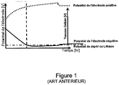
- This lithium deposition problem identified and treated alternatively in WO2011 / 152062 A1 is a problem associated with charging and / or regenerative braking.
- the lithium deposit seems to be related to the potential of the negative electrode, which is not, by construction, directly measured by the voltage of the cell (the cell voltage being only the difference between the potentials of the positive and negative electrodes ).
- Lithium deposition is explained by the fact that, under certain conditions of current, temperature, state of charge and aging, the lithium deposition reaction is more kinetically favored than the reaction of lithium. intercalation of lithium in graphite carbon. This occurs when the negative electrode falls below the lithium deposition potential for a sufficiently long time, for example in the range of 5 s to 20 min. This happens more easily when cold.
- WO 2011 122946 A2 aims to manage a compromise between charging time and durability.
- this document teaches the principle of a modification of the charging logic as a function of the temperature.
- the improvement in the durability of the battery comes from a charging logic which, on the one hand, promotes battery heating at the beginning of cold charging by the application of current pulses.
- English "Pulse Width Modulation” “Pulse Width Modulation”
- This solution therefore amounts to terminating the load in constant voltage, which can cause the negative electrode under the potential of deposition of lithium for a significant undesirable duration.
- the lithium deposition mechanisms seem not only related to the potential level of the negative electrode, but also to the aspect duration during which the negative electrode falls below this level of lithium deposition potential. .
- the implementation of the method may allow the control of a charger to achieve a relatively large drop in the allowable power load, the charging voltage or the charging current, so that the potential of the electrode Negative is only passed for a short time, for example in the range of 5 s to 20 min, below the lithium deposition potential.
- the deposition of lithium will be all the more easily that there is already deposited lithium in metallic form on the negative electrode.
- control signal may advantageously have "abrupt" variations, for example power drops of between 1 and 20 kW, or, in other words, rapid drops in order to oscillate the potential of the negative electrode to prevent this potential value becomes lower than the lithium deposition potential.
- the control signal can therefore have a generally decreasing appearance with relatively abrupt variations, for example discontinuities, decreasing exponentials or the like, these abrupt variations making it possible to temporarily increase the values of the potential of the negative electrode to prevent these these are lower than the lithium deposition potential during undesirable important durations.
- the determined value of voltage may advantageously be a predetermined end of charge voltage or a voltage determined by another parameter.
- the method of the invention can very advantageously be implemented by a battery control system BMS, which decides to calculate the permissible power under load in order to save the cell durability, in particular by limiting the deposition of lithium to the electrode. negative of each cell, when the charge temperature value (T ° C charge ), measured instantaneously from the beginning to the end of charge, is lower than the threshold temperature value (step c)).
- BMS battery control system
- the method may further comprise a step of receiving a measured value of the charging voltage and a step of comparing the measured value of the received charge voltage with a determined value of threshold voltage across the battery, wherein the control signal is generated in decreasing steps when the measured temperature value is less than or equal to the threshold temperature value and when the charging voltage is greater than a threshold voltage.
- the determined voltage may be the cut-off voltage.
- the BMS system can apply a charge CP-CV, as long as the cut-off voltage remains, for example, less than a threshold voltage of 4.10 V, and / or can apply a multi-step load as soon as, for example, the breaking voltage exceeds for example this threshold voltage of 4.10 V.
- the method of the invention may be a so-called "multi-step” charging method, which may advantageously be implemented when the temperature of the battery during charging is lower than the predetermined threshold temperature value and, optionally, when the charging voltage is high, the charging voltage may advantageously be the breaking voltage.
- the so-called multi-step charging method can be implemented for these two conditions combined.
- steps a), b), c) and d) can be regularly repeated during the same load.
- the method can be implemented via loops, with a waiting step ( ⁇ ) between the execution of two successive loops.
- This waiting time may for example be from 5 minutes to 1 hour. This can make it possible to change the charging strategy at intervals, for example regular, depending on whether the temperature of the battery passes above or below the predetermined threshold temperature.
- steps a) and b) can be performed once, at the start of charging.
- the load strategy is determined from the start of charging.
- the waiting step may for example take values between 40 and 50 hours.
- signal is understood to mean, for example, an electrical, differential, analog or other signal, such as an electromagnetic or pressure signal.
- the threshold temperature (T threshold ° C) is generally between -10 ° C and 30 ° C. This temperature can be determined according to the electrochemical characteristics of the cell.
- T ° C charge when T ° C charge is less than or equal to T ° C threshold , the difference can be at least one degree Celsius, more preferably, a few degrees.
- T ° C load is less than T ° C threshold of 1 degree, 2 degrees, or even 3 degrees Celsius.
- the charging temperature is less than or equal to threshold T ° C, (steps a) and b))
- it is for example carried out by charging the battery with a charger at a first stage of maximum power determined, for example 40 kW.
- the maximum cell voltage V cell max the cut-off voltage is reached, the next load power stage, which is lower than the previous step, for example 35 kW, and so on, until the load power is 0 kW, is switched to.
- the charging power can preferably, when the measured temperature value is less than or equal to the threshold temperature value, decrease in increments within the range of 5 kW to 10 KW, or even in the range of values of 5 kW. kW to 20 KW depending on the case, for load powers above a certain power threshold, and in steps ranging from 1 to 1.5 kW, or even 1 to 5 kW depending on the case, for load powers below this determined power threshold.
- the power threshold determined is preferably between 10 kW and about 15 kW.
- the load power threshold may be predetermined before the implementation of the method or, according to embodiments, determined during the execution of the method.
- a step or each power level can be maintained for a period of time preferably between 10 s and 25 min, in particular between 10 s and 20 min.
- the first step may be specifically implemented for periods longer than those of other subsequent levels, typically of the order of 15 s to 25 min.
- the maximum charge power of each cell or generally of the Li-ion battery may depend on the Li-ion battery used, and may usually be at most 50 kW.
- the Li-ion battery is in no way limited, and may preferably be a battery in which the lithium remains in the ionic state thanks to the use of an insertion compound as well as the negative electrode, generally graphite, than the positive electrode, which may be cobalt oxide, manganese oxide or iron phosphate.
- the Li-ion batteries mention may be made of so-called “lithium metal-polymer” and “lithium-air” batteries.
- the Li-ion batteries of the invention may be applicable in various technological fields, such as automobiles, computers or telecoms, and may be suitable for on-board or off-board systems.
- the method of the invention can be implemented by any type of chargers known to those skilled in the art, especially commercially available, and chargers are not limited.
- the method may further include a step of determining the threshold value of T ° C, depending on the state of aging of the battery. For example, this value can be selected from a plurality of predetermined threshold temperature values, depending on the aging state of the battery.
- the charge control signal when the temperature of the battery being charged is in particular greater than the threshold temperature value, is designed so as to control a fast charging phase with rapid increasing voltage and then a phase current-decreasing absorption device regulated at a predetermined voltage value, for example a breaking voltage.
- the method may further comprise a step of heating the Li-ion battery, particularly throughout the charge.
- Such a stage of reheating of the battery can make it possible to adapt and / or modify the charge, for example at regular intervals, as a function of the evolution during the charging time of the temperature of the battery.
- the charge of the battery is a multi-step charge.
- the BMS system can implement a charge of the battery according to a charge CP-CV or CC-CV, whatever the value of the cut-off voltage.
- this load selection strategy it is possible to apply this load selection strategy to a battery having a device for heating said battery. It may then be possible to simultaneously heat and charge the battery, according to the above strategy.
- the BMS system can modulate the cut-off voltage according to the state of aging of the battery.
- a CP-CV type load with a low cut-off voltage typically of the order of 4.05 V
- a CP-CV load with a high cut-off voltage for example 4.2 V, imposed by the BMS system at the end of battery life, may degrade the battery due to lithium deposition.
- the multi-stage charge can be advantageously implemented if the cut-off voltage is high and if the temperature of the battery during charging is lower than the predetermined threshold temperature value.
- the determined voltage value may advantageously be a predetermined end of charge voltage or a voltage determined by another parameter.
- the device may further include means for calculating the allowable power load to minimize charging time, when the charge start temperature is above the threshold temperature.
- Such a device is in particular adapted to the implementation of the above method with the different variants.
- the receiving means may comprise, for example, an input pin, an input port and the like.
- the processing means may comprise a processor core or CPU (of the "Central Processing Unit"), a processor or other.
- the transmission means may for example comprise an output pin, an output port or the like.
- a management device can very advantageously be a BMS system, which is preferably an integral part of the Li-ion battery.
- the invention relates to a computer program comprising instructions for carrying out the steps of the method of the invention, when these instructions are executed by a processor.
- this computer program can be stored in a memory of the load management device.
- the invention also relates to a lithium-ion battery pack comprising a lithium-ion battery and a charge management device for the battery, as described above.
- the invention also relates to a motor vehicle incorporating a lithium-ion battery and the charge management device described above and / or a battery pack, as described above.
- the invention is illustrated by the figures and non-limiting examples which follow.
- the first step of the method is the reception 101 of a temperature value T of a lithium-ion battery at the beginning of charging, implemented by a BMS system.
- a threshold temperature value (T THR ) here estimated as a function of the aging of the battery (f (SOHE)) 102 is determined.
- T THR can be equal to 15 ° C.
- the threshold voltage is also here estimated as a function of the state of aging of the battery (f 2 (SOHE)) 102 '.
- the second step (step b) 103 is, on the one hand, the comparison of this measured temperature value (T), according to 101, with the threshold temperature (T THR ) and the comparison of the cutoff voltage (V cut -off ) with the threshold voltage (V THR ).
- the BMS system When this measured temperature (T) is lower than T THR , and when V cut-off is greater than V THR , then the BMS system generates a charge control signal of the battery according to the multi-step channel of the invention ( step 104).
- the control signal S is then transmitted to a charger of the lithium-ion battery during a step 105.
- the charging strategy is therefore a function of the parameters above.
- the method also comprises a waiting step ( ⁇ ) between the execution of two loops, that is to say the implementation of the steps 101, 102, 102 ', 103, 104, 104' and 105.
- the Figure 3 A and B correspond to a charging strategy of a Li-ion battery according to an example of the invention, when the charging temperature is less than or equal to the threshold temperature here fixed at 15 ° C.
- Figure 3A represents an example of a load graph in decreasing power steps, starting at 50 kW for 20 min, the second bearing being fixed at 32 k W for 10 min, the third step being fixed at 6 kW for 7 min, the fourth bearing being set at 2 kW for 8 min until reaching zero load power.
- the figure 3B represents an example of an evolution of the potential of the negative electrode of the Li-ion battery as a function of the charging time, when applying the charging strategy corresponding to the Figure 3A .
- the potential of the electrode is lower than that of lithium deposition for a relatively short time, in this case by 10 s, at each decay of the power, which, of a on the other hand, can also increase the durability of the battery while optimizing the charging time without degradation of the battery including over-voltages.
- an example of a motor vehicle 10 comprises a traction battery assembly 11, which can be charged by means of a charger (not shown), for example a charging terminal connected to the electrical network.
- the battery 12 may for example be a lithium ion battery.
- the charger can for example be a fast charging terminal supplying a direct current to the battery pack 11 of the vehicle 10.
- the battery pack 11 can integrate a charge management device 13, for example a BMS type battery control system, which system comprises a processor (not shown) executing a program comprising instructions for adapting and / or modifying charging strategy at regular intervals, depending on the evolution over the charging time of the battery temperature and the cut-off voltage.
- a charge management device 13 for example a BMS type battery control system, which system comprises a processor (not shown) executing a program comprising instructions for adapting and / or modifying charging strategy at regular intervals, depending on the evolution over the charging time of the battery temperature and the cut-off voltage.
- An example of load strategy is given to the Figure 3 .
- the load management device 13 comprises means for receiving a temperature value of the battery and the cut-off voltage (not shown), for example an input pin in electrical communication with sensors (not shown). of the motor vehicle 10.
- the device 13 comprises processing means (not shown), arranged to compare, on the one hand, the measured temperature value with a threshold temperature value and, on the other hand, the cut-off voltage with a threshold voltage, which are a core of a processor, and signal transmission means (not shown) to a loader, which are an output pin.
Landscapes
- Engineering & Computer Science (AREA)
- Power Engineering (AREA)
- Manufacturing & Machinery (AREA)
- Chemical & Material Sciences (AREA)
- Chemical Kinetics & Catalysis (AREA)
- Electrochemistry (AREA)
- General Chemical & Material Sciences (AREA)
- Charge And Discharge Circuits For Batteries Or The Like (AREA)
- Secondary Cells (AREA)
Claims (11)
- Verfahren zur Verwaltung einer Ladung einer Lithium-Ionen-Batterie, umfassend die folgenden Schritte:a) Empfang (101) eines Messwerts der Temperatur der Batterie;b) Vergleich (103) des in Schritt a) empfangenen Messwerts mit einem vorbestimmten Grenztemperaturwert;c) Erzeugung (104, 104') eines Ladesteuersignals der Batterie, wobei das Steuersignal derart erzeugt wird, dass, wenn der Temperaturmesswert kleiner oder gleich dem Grenztemperaturwert ist, die Ladeleistung, die Ladespannung oder die Ladestärke stufenweise abnimmt, wobei der Übergang von einer Stufe zur nächsten ausgelöst wird, sobald ein bestimmter Spannungswert an den Klemmen der Batterie erreicht ist, undd) Übertragung (105) des Steuersignals zu einem Ladegerät.
- Verfahren nach Anspruch 1, bei dem, wenn der Temperaturmesswert kleiner oder gleich dem Grenztemperaturwert ist, die Ladeleistung stufenweise in dem Wertebereich von 5 kW bis 10 kW für Ladeleistungen über einer bestimmten Leistungsgrenze und stufenweise in dem Wertebereich von 1 kW bis 1,5 kW für Ladeleistungen unter dieser bestimmten Leistungsgrenze abnimmt.
- Verfahren nach Anspruch 1 oder 2, bei dem der Temperaturmesswert kleiner oder gleich dem Grenztemperaturwert ist, eine Leistungsstufe während einer Dauer zwischen 10s und 25min aufrechterhalten wird.
- Verfahren nach einem der Ansprüche 1 bis 3, bei dem die Schritte a), b), c) und d) während einer selben Ladung regelmäßig wiederholt werden.
- Verfahren nach einem der Ansprüche 1 bis 3, bei dem die Schritte a) und b) einmal am Ladebeginn ausgeführt werden.
- Verfahren nach einem der Ansprüche 1 bis 5, ferner umfassend einen Schritt der Bestimmung des Grenztemperaturwerts in Abhängigkeit vom Alterungszustand der Batterie (102).
- Verfahren nach einem der Ansprüche 1 bis 6, bei dem, wenn die Temperatur der Batterie während des Ladens höher als der Grenztemperaturwert ist, das Ladesteuersignal erzeugt wird, um eine rasche Ladephase mit rasch steigender Spannung, dann eine Absorptionsphase mit abnehmendem Strom, der auf einen vorbestimmten Spannungswert, beispielsweise eine Abschaltspannung, eingestellt ist, zu steuern.
- Verfahren nach einem der Ansprüche 1 bis 7, ferner umfassend einen Schritt des Empfangs eines Messwerts der Ladespannung und einen Schritt des Vergleichs des Messwerts der empfangenen Ladespannung mit einem bestimmten Grenzspannungswert an den Klemmen der Batterie, bei dem das Steuersignal in abnehmenden Stufen erzeugt wird, wenn der Temperaturmesswert kleiner oder gleich dem Grenztemperaturwert ist, oder wenn die Ladespannung höher als ein Grenzspannungswert ist.
- Computerprogramm, umfassend Anweisungen, um die Schritte des Verfahrens nach einem der Ansprüche 1 bis 8 auszuführen, wenn diese Anweisungen von einem Prozessor ausgeführt werden.
- Vorrichtung zur Verwaltung einer Ladung einer Lithium-Ionen-Batterie (13), umfassend:- Mittel zum Empfang eines Messwerts der Temperatur der Batterie, die von einem Temperaturfühler kommt;- Bearbeitungsmittel, die dazu vorgesehen sind, den Messwert mit einem vorbestimmten Grenztemperaturwert zu vergleichen, und ein Ladesteuersignal der Batterie zu erzeugen, wobei die Bearbeitungsmittel derart vorgesehen sind, dass, wenn der Temperaturmesswert kleiner oder gleich dem Grenztemperaturwert ist, das Steuersignal derart erzeugt wird, dass die Ladeleistung, die Ladespannung oder die Ladestärke stufenweise abnimmt, wobei der Übergang von einer Stufe zur nächsten ausgelöst wird, sobald ein bestimmter Spannungswert an den Klemmen der Batterie erreicht ist, und- Mittel zur Übertragung des Steuersignals zu einem Ladegerät.
- Kraftfahrzeug, umfassend eine Lithium-Ionen-Batterie (12) und eine Ladevorrichtung (13) nach Anspruch 10.
Applications Claiming Priority (2)
| Application Number | Priority Date | Filing Date | Title |
|---|---|---|---|
| FR1352033A FR3003100B1 (fr) | 2013-03-07 | 2013-03-07 | Gestion de charge d'une batterie |
| PCT/FR2014/050511 WO2014135807A2 (fr) | 2013-03-07 | 2014-03-06 | Gestion de charge d'une batterie |
Publications (2)
| Publication Number | Publication Date |
|---|---|
| EP2965399A2 EP2965399A2 (de) | 2016-01-13 |
| EP2965399B1 true EP2965399B1 (de) | 2019-09-11 |
Family
ID=48613854
Family Applications (1)
| Application Number | Title | Priority Date | Filing Date |
|---|---|---|---|
| EP14713541.2A Active EP2965399B1 (de) | 2013-03-07 | 2014-03-06 | Verwaltung der batterieladung |
Country Status (4)
| Country | Link |
|---|---|
| EP (1) | EP2965399B1 (de) |
| KR (1) | KR102024282B1 (de) |
| FR (1) | FR3003100B1 (de) |
| WO (1) | WO2014135807A2 (de) |
Cited By (1)
| Publication number | Priority date | Publication date | Assignee | Title |
|---|---|---|---|---|
| US12015290B2 (en) | 2020-10-30 | 2024-06-18 | Techtronic Cordless Gp | Battery pack with temperature limited current |
Families Citing this family (1)
| Publication number | Priority date | Publication date | Assignee | Title |
|---|---|---|---|---|
| KR102688561B1 (ko) * | 2018-04-16 | 2024-07-26 | 이씨 파워, 엘엘씨 | 가열을 통한 배터리 충전 시스템 및 방법 |
Family Cites Families (5)
| Publication number | Priority date | Publication date | Assignee | Title |
|---|---|---|---|---|
| JP4653219B2 (ja) * | 2005-06-10 | 2011-03-16 | アギア システムズ インコーポレーテッド | 再充電可能なバッテリの多閾値充電 |
| US8624560B2 (en) * | 2008-04-11 | 2014-01-07 | Apple Inc. | Controlling battery charging based on current, voltage and temperature |
| NL2004503C2 (en) | 2010-04-02 | 2011-10-04 | Epyon B V | Method and device for charging a battery and battery charger. |
| JP5782803B2 (ja) * | 2010-06-03 | 2015-09-24 | 日産自動車株式会社 | 電池の充電装置および電池の充電方法 |
| JP5304844B2 (ja) * | 2011-05-24 | 2013-10-02 | トヨタ自動車株式会社 | バッテリの充電制御装置 |
-
2013
- 2013-03-07 FR FR1352033A patent/FR3003100B1/fr not_active Expired - Fee Related
-
2014
- 2014-03-06 EP EP14713541.2A patent/EP2965399B1/de active Active
- 2014-03-06 KR KR1020157027740A patent/KR102024282B1/ko not_active Expired - Fee Related
- 2014-03-06 WO PCT/FR2014/050511 patent/WO2014135807A2/fr not_active Ceased
Non-Patent Citations (1)
| Title |
|---|
| None * |
Cited By (2)
| Publication number | Priority date | Publication date | Assignee | Title |
|---|---|---|---|---|
| US12015290B2 (en) | 2020-10-30 | 2024-06-18 | Techtronic Cordless Gp | Battery pack with temperature limited current |
| US12463437B2 (en) | 2020-10-30 | 2025-11-04 | Techtronic Cordless Gp | Battery pack with temperature limited current |
Also Published As
| Publication number | Publication date |
|---|---|
| FR3003100A1 (fr) | 2014-09-12 |
| WO2014135807A3 (fr) | 2014-11-27 |
| KR102024282B1 (ko) | 2019-09-23 |
| KR20150122800A (ko) | 2015-11-02 |
| FR3003100B1 (fr) | 2015-02-27 |
| WO2014135807A2 (fr) | 2014-09-12 |
| EP2965399A2 (de) | 2016-01-13 |
Similar Documents
| Publication | Publication Date | Title |
|---|---|---|
| EP2957018B1 (de) | Verwaltung der aufladung einer batterie | |
| EP3237258B1 (de) | Verfahren zur energieverwaltung einer wiederaufladbaren traktionsbatterie eines hybridfahrzeugs | |
| FR3065292B1 (fr) | Methode de gestion d'une batterie en fonction de son etat de sante | |
| FR3025663A1 (fr) | Procede de gestion de la plage d'utilisation d'une batterie | |
| EP2721713B1 (de) | Verfahren zur enerigeversorgung eines elektrischen zubehörs eines kraftfahrzeuges mit einer elektrischen batterie, an die dieses zubehör angeschlossen ist | |
| EP2774210B1 (de) | Steuerungsverfahren der funktion eines hybridsystems | |
| WO2020074397A1 (fr) | Procédé et dispositif de régulation du niveau de charge d'une batterie de traction d'un véhicule électrique | |
| EP2965399B1 (de) | Verwaltung der batterieladung | |
| EP2945817A1 (de) | Verwaltung der ladung einer batterie | |
| WO2021209259A1 (fr) | Procédé de calibration d'un courant de charge d'une batterie d'un véhicule automobile électrique | |
| EP4101047B1 (de) | Verfahren zur impulsladung mit variablem amplitudenschritt | |
| FR2982206A1 (fr) | Dispositif et procede de gestion d'une batterie en vue de sa non utilisation pendant une duree choisie | |
| EP3235048A1 (de) | Verfahren und vorrichtung zum laden einer lithium-ionen-batterie mit impulsen | |
| FR3152595A1 (fr) | Procede de charge rapide d’un systeme de batterie | |
| FR3152594A1 (fr) | Procede de controle de courant d’un systeme de batterie en fonction d’une estimation de la concentration en lithium en surface d’une electrode | |
| WO2024180285A1 (fr) | Procede de charge rapide impulsionnelle a paliers de tension d'amplitude regulee | |
| FR3156537A1 (fr) | Procede de controle d’un courant en fonction d’un compteur a incrementation modulable pour un systeme de batterie | |
| EP4382930A1 (de) | Verfahren zur verwaltung einer batterie | |
| FR3152922A1 (fr) | Gestion des recharges d’une batterie cellulaire d’un système en fonction de la chimie des cellules | |
| FR3152672A1 (fr) | Gestion des recharges d’une batterie cellulaire d’un système en fonction de l’état de charge désiré | |
| FR3122786A1 (fr) | Procede de gestion d’un niveau de charge d’un stockeur d’energie basse tension | |
| EP4533629A1 (de) | Verfahren zur erkennung eines ausfallrisikos durch ungleichgewicht einer vorrichtung zur speicherung von energie mit einem satz von stufen elektrochemischer zellen | |
| EP4723424A1 (de) | Verfahren und system zum laden einer batterie | |
| WO2023001830A1 (fr) | Véhicule comprenant une batterie rechargeable et des moyens de détermination d'une puissance maximale admissible pour la batterie lors d'une phase de charge | |
| EP2094524A2 (de) | Verfahren zur verwaltung von energieflüssen in einem elektrischen stromversorgungsgerät |
Legal Events
| Date | Code | Title | Description |
|---|---|---|---|
| PUAI | Public reference made under article 153(3) epc to a published international application that has entered the european phase |
Free format text: ORIGINAL CODE: 0009012 |
|
| 17P | Request for examination filed |
Effective date: 20150902 |
|
| AK | Designated contracting states |
Kind code of ref document: A2 Designated state(s): AL AT BE BG CH CY CZ DE DK EE ES FI FR GB GR HR HU IE IS IT LI LT LU LV MC MK MT NL NO PL PT RO RS SE SI SK SM TR |
|
| AX | Request for extension of the european patent |
Extension state: BA ME |
|
| DAX | Request for extension of the european patent (deleted) | ||
| GRAP | Despatch of communication of intention to grant a patent |
Free format text: ORIGINAL CODE: EPIDOSNIGR1 |
|
| STAA | Information on the status of an ep patent application or granted ep patent |
Free format text: STATUS: GRANT OF PATENT IS INTENDED |
|
| RIC1 | Information provided on ipc code assigned before grant |
Ipc: H01M 10/052 20100101ALN20181009BHEP Ipc: H01M 10/44 20060101ALI20181009BHEP Ipc: H02J 7/00 20060101AFI20181009BHEP |
|
| INTG | Intention to grant announced |
Effective date: 20181025 |
|
| GRAS | Grant fee paid |
Free format text: ORIGINAL CODE: EPIDOSNIGR3 |
|
| GRAJ | Information related to disapproval of communication of intention to grant by the applicant or resumption of examination proceedings by the epo deleted |
Free format text: ORIGINAL CODE: EPIDOSDIGR1 |
|
| GRAL | Information related to payment of fee for publishing/printing deleted |
Free format text: ORIGINAL CODE: EPIDOSDIGR3 |
|
| GRAP | Despatch of communication of intention to grant a patent |
Free format text: ORIGINAL CODE: EPIDOSNIGR1 |
|
| RIC1 | Information provided on ipc code assigned before grant |
Ipc: H01M 10/44 20060101ALI20190304BHEP Ipc: H01M 10/052 20100101ALN20190304BHEP Ipc: H02J 7/00 20060101AFI20190304BHEP |
|
| RIC1 | Information provided on ipc code assigned before grant |
Ipc: H01M 10/052 20100101ALN20190318BHEP Ipc: H02J 7/00 20060101AFI20190318BHEP Ipc: H01M 10/44 20060101ALI20190318BHEP |
|
| RIN1 | Information on inventor provided before grant (corrected) |
Inventor name: SAINT-MARCOUX, ANTOINE Inventor name: GIRAUD, MARC-HENRI Inventor name: DELOBEL, BRUNO |
|
| INTG | Intention to grant announced |
Effective date: 20190408 |
|
| GRAA | (expected) grant |
Free format text: ORIGINAL CODE: 0009210 |
|
| STAA | Information on the status of an ep patent application or granted ep patent |
Free format text: STATUS: THE PATENT HAS BEEN GRANTED |
|
| AK | Designated contracting states |
Kind code of ref document: B1 Designated state(s): AL AT BE BG CH CY CZ DE DK EE ES FI FR GB GR HR HU IE IS IT LI LT LU LV MC MK MT NL NO PL PT RO RS SE SI SK SM TR |
|
| REG | Reference to a national code |
Ref country code: GB Ref legal event code: FG4D Free format text: NOT ENGLISH |
|
| REG | Reference to a national code |
Ref country code: CH Ref legal event code: EP |
|
| REG | Reference to a national code |
Ref country code: AT Ref legal event code: REF Ref document number: 1179745 Country of ref document: AT Kind code of ref document: T Effective date: 20190915 |
|
| REG | Reference to a national code |
Ref country code: DE Ref legal event code: R096 Ref document number: 602014053380 Country of ref document: DE Ref country code: IE Ref legal event code: FG4D Free format text: LANGUAGE OF EP DOCUMENT: FRENCH |
|
| REG | Reference to a national code |
Ref country code: NL Ref legal event code: MP Effective date: 20190911 |
|
| REG | Reference to a national code |
Ref country code: LT Ref legal event code: MG4D |
|
| PG25 | Lapsed in a contracting state [announced via postgrant information from national office to epo] |
Ref country code: LT Free format text: LAPSE BECAUSE OF FAILURE TO SUBMIT A TRANSLATION OF THE DESCRIPTION OR TO PAY THE FEE WITHIN THE PRESCRIBED TIME-LIMIT Effective date: 20190911 Ref country code: FI Free format text: LAPSE BECAUSE OF FAILURE TO SUBMIT A TRANSLATION OF THE DESCRIPTION OR TO PAY THE FEE WITHIN THE PRESCRIBED TIME-LIMIT Effective date: 20190911 Ref country code: NO Free format text: LAPSE BECAUSE OF FAILURE TO SUBMIT A TRANSLATION OF THE DESCRIPTION OR TO PAY THE FEE WITHIN THE PRESCRIBED TIME-LIMIT Effective date: 20191211 Ref country code: BG Free format text: LAPSE BECAUSE OF FAILURE TO SUBMIT A TRANSLATION OF THE DESCRIPTION OR TO PAY THE FEE WITHIN THE PRESCRIBED TIME-LIMIT Effective date: 20191211 Ref country code: SE Free format text: LAPSE BECAUSE OF FAILURE TO SUBMIT A TRANSLATION OF THE DESCRIPTION OR TO PAY THE FEE WITHIN THE PRESCRIBED TIME-LIMIT Effective date: 20190911 Ref country code: HR Free format text: LAPSE BECAUSE OF FAILURE TO SUBMIT A TRANSLATION OF THE DESCRIPTION OR TO PAY THE FEE WITHIN THE PRESCRIBED TIME-LIMIT Effective date: 20190911 |
|
| PG25 | Lapsed in a contracting state [announced via postgrant information from national office to epo] |
Ref country code: LV Free format text: LAPSE BECAUSE OF FAILURE TO SUBMIT A TRANSLATION OF THE DESCRIPTION OR TO PAY THE FEE WITHIN THE PRESCRIBED TIME-LIMIT Effective date: 20190911 Ref country code: GR Free format text: LAPSE BECAUSE OF FAILURE TO SUBMIT A TRANSLATION OF THE DESCRIPTION OR TO PAY THE FEE WITHIN THE PRESCRIBED TIME-LIMIT Effective date: 20191212 Ref country code: RS Free format text: LAPSE BECAUSE OF FAILURE TO SUBMIT A TRANSLATION OF THE DESCRIPTION OR TO PAY THE FEE WITHIN THE PRESCRIBED TIME-LIMIT Effective date: 20190911 Ref country code: AL Free format text: LAPSE BECAUSE OF FAILURE TO SUBMIT A TRANSLATION OF THE DESCRIPTION OR TO PAY THE FEE WITHIN THE PRESCRIBED TIME-LIMIT Effective date: 20190911 Ref country code: ES Free format text: LAPSE BECAUSE OF FAILURE TO SUBMIT A TRANSLATION OF THE DESCRIPTION OR TO PAY THE FEE WITHIN THE PRESCRIBED TIME-LIMIT Effective date: 20190911 |
|
| REG | Reference to a national code |
Ref country code: AT Ref legal event code: MK05 Ref document number: 1179745 Country of ref document: AT Kind code of ref document: T Effective date: 20190911 |
|
| PG25 | Lapsed in a contracting state [announced via postgrant information from national office to epo] |
Ref country code: PL Free format text: LAPSE BECAUSE OF FAILURE TO SUBMIT A TRANSLATION OF THE DESCRIPTION OR TO PAY THE FEE WITHIN THE PRESCRIBED TIME-LIMIT Effective date: 20190911 Ref country code: EE Free format text: LAPSE BECAUSE OF FAILURE TO SUBMIT A TRANSLATION OF THE DESCRIPTION OR TO PAY THE FEE WITHIN THE PRESCRIBED TIME-LIMIT Effective date: 20190911 Ref country code: NL Free format text: LAPSE BECAUSE OF FAILURE TO SUBMIT A TRANSLATION OF THE DESCRIPTION OR TO PAY THE FEE WITHIN THE PRESCRIBED TIME-LIMIT Effective date: 20190911 Ref country code: AT Free format text: LAPSE BECAUSE OF FAILURE TO SUBMIT A TRANSLATION OF THE DESCRIPTION OR TO PAY THE FEE WITHIN THE PRESCRIBED TIME-LIMIT Effective date: 20190911 Ref country code: IT Free format text: LAPSE BECAUSE OF FAILURE TO SUBMIT A TRANSLATION OF THE DESCRIPTION OR TO PAY THE FEE WITHIN THE PRESCRIBED TIME-LIMIT Effective date: 20190911 Ref country code: PT Free format text: LAPSE BECAUSE OF FAILURE TO SUBMIT A TRANSLATION OF THE DESCRIPTION OR TO PAY THE FEE WITHIN THE PRESCRIBED TIME-LIMIT Effective date: 20200113 Ref country code: RO Free format text: LAPSE BECAUSE OF FAILURE TO SUBMIT A TRANSLATION OF THE DESCRIPTION OR TO PAY THE FEE WITHIN THE PRESCRIBED TIME-LIMIT Effective date: 20190911 |
|
| PG25 | Lapsed in a contracting state [announced via postgrant information from national office to epo] |
Ref country code: SM Free format text: LAPSE BECAUSE OF FAILURE TO SUBMIT A TRANSLATION OF THE DESCRIPTION OR TO PAY THE FEE WITHIN THE PRESCRIBED TIME-LIMIT Effective date: 20190911 Ref country code: CZ Free format text: LAPSE BECAUSE OF FAILURE TO SUBMIT A TRANSLATION OF THE DESCRIPTION OR TO PAY THE FEE WITHIN THE PRESCRIBED TIME-LIMIT Effective date: 20190911 Ref country code: IS Free format text: LAPSE BECAUSE OF FAILURE TO SUBMIT A TRANSLATION OF THE DESCRIPTION OR TO PAY THE FEE WITHIN THE PRESCRIBED TIME-LIMIT Effective date: 20200224 Ref country code: SK Free format text: LAPSE BECAUSE OF FAILURE TO SUBMIT A TRANSLATION OF THE DESCRIPTION OR TO PAY THE FEE WITHIN THE PRESCRIBED TIME-LIMIT Effective date: 20190911 |
|
| REG | Reference to a national code |
Ref country code: DE Ref legal event code: R097 Ref document number: 602014053380 Country of ref document: DE |
|
| PLBE | No opposition filed within time limit |
Free format text: ORIGINAL CODE: 0009261 |
|
| STAA | Information on the status of an ep patent application or granted ep patent |
Free format text: STATUS: NO OPPOSITION FILED WITHIN TIME LIMIT |
|
| PG2D | Information on lapse in contracting state deleted |
Ref country code: IS |
|
| PG25 | Lapsed in a contracting state [announced via postgrant information from national office to epo] |
Ref country code: DK Free format text: LAPSE BECAUSE OF FAILURE TO SUBMIT A TRANSLATION OF THE DESCRIPTION OR TO PAY THE FEE WITHIN THE PRESCRIBED TIME-LIMIT Effective date: 20190911 Ref country code: IS Free format text: LAPSE BECAUSE OF FAILURE TO SUBMIT A TRANSLATION OF THE DESCRIPTION OR TO PAY THE FEE WITHIN THE PRESCRIBED TIME-LIMIT Effective date: 20200112 |
|
| 26N | No opposition filed |
Effective date: 20200615 |
|
| PG25 | Lapsed in a contracting state [announced via postgrant information from national office to epo] |
Ref country code: SI Free format text: LAPSE BECAUSE OF FAILURE TO SUBMIT A TRANSLATION OF THE DESCRIPTION OR TO PAY THE FEE WITHIN THE PRESCRIBED TIME-LIMIT Effective date: 20190911 |
|
| PG25 | Lapsed in a contracting state [announced via postgrant information from national office to epo] |
Ref country code: MC Free format text: LAPSE BECAUSE OF FAILURE TO SUBMIT A TRANSLATION OF THE DESCRIPTION OR TO PAY THE FEE WITHIN THE PRESCRIBED TIME-LIMIT Effective date: 20190911 |
|
| REG | Reference to a national code |
Ref country code: CH Ref legal event code: PL |
|
| REG | Reference to a national code |
Ref country code: BE Ref legal event code: MM Effective date: 20200331 |
|
| PG25 | Lapsed in a contracting state [announced via postgrant information from national office to epo] |
Ref country code: LU Free format text: LAPSE BECAUSE OF NON-PAYMENT OF DUE FEES Effective date: 20200306 |
|
| PG25 | Lapsed in a contracting state [announced via postgrant information from national office to epo] |
Ref country code: LI Free format text: LAPSE BECAUSE OF NON-PAYMENT OF DUE FEES Effective date: 20200331 Ref country code: CH Free format text: LAPSE BECAUSE OF NON-PAYMENT OF DUE FEES Effective date: 20200331 Ref country code: IE Free format text: LAPSE BECAUSE OF NON-PAYMENT OF DUE FEES Effective date: 20200306 |
|
| PG25 | Lapsed in a contracting state [announced via postgrant information from national office to epo] |
Ref country code: BE Free format text: LAPSE BECAUSE OF NON-PAYMENT OF DUE FEES Effective date: 20200331 |
|
| PG25 | Lapsed in a contracting state [announced via postgrant information from national office to epo] |
Ref country code: TR Free format text: LAPSE BECAUSE OF FAILURE TO SUBMIT A TRANSLATION OF THE DESCRIPTION OR TO PAY THE FEE WITHIN THE PRESCRIBED TIME-LIMIT Effective date: 20190911 Ref country code: MT Free format text: LAPSE BECAUSE OF FAILURE TO SUBMIT A TRANSLATION OF THE DESCRIPTION OR TO PAY THE FEE WITHIN THE PRESCRIBED TIME-LIMIT Effective date: 20190911 Ref country code: CY Free format text: LAPSE BECAUSE OF FAILURE TO SUBMIT A TRANSLATION OF THE DESCRIPTION OR TO PAY THE FEE WITHIN THE PRESCRIBED TIME-LIMIT Effective date: 20190911 |
|
| PG25 | Lapsed in a contracting state [announced via postgrant information from national office to epo] |
Ref country code: MK Free format text: LAPSE BECAUSE OF FAILURE TO SUBMIT A TRANSLATION OF THE DESCRIPTION OR TO PAY THE FEE WITHIN THE PRESCRIBED TIME-LIMIT Effective date: 20190911 |
|
| PGFP | Annual fee paid to national office [announced via postgrant information from national office to epo] |
Ref country code: FR Payment date: 20230324 Year of fee payment: 10 |
|
| PGFP | Annual fee paid to national office [announced via postgrant information from national office to epo] |
Ref country code: GB Payment date: 20230322 Year of fee payment: 10 Ref country code: DE Payment date: 20230321 Year of fee payment: 10 |
|
| P01 | Opt-out of the competence of the unified patent court (upc) registered |
Effective date: 20230608 |
|
| REG | Reference to a national code |
Ref country code: DE Ref legal event code: R081 Ref document number: 602014053380 Country of ref document: DE Owner name: AMPERE S.A.S., FR Free format text: FORMER OWNER: RENAULT S.A.S., BOULOGNE-BILLANCOURT, FR |
|
| REG | Reference to a national code |
Ref country code: DE Ref legal event code: R119 Ref document number: 602014053380 Country of ref document: DE |
|
| GBPC | Gb: european patent ceased through non-payment of renewal fee |
Effective date: 20240306 |
|
| PG25 | Lapsed in a contracting state [announced via postgrant information from national office to epo] |
Ref country code: DE Free format text: LAPSE BECAUSE OF NON-PAYMENT OF DUE FEES Effective date: 20241001 |
|
| PG25 | Lapsed in a contracting state [announced via postgrant information from national office to epo] |
Ref country code: GB Free format text: LAPSE BECAUSE OF NON-PAYMENT OF DUE FEES Effective date: 20240306 |
|
| PG25 | Lapsed in a contracting state [announced via postgrant information from national office to epo] |
Ref country code: FR Free format text: LAPSE BECAUSE OF NON-PAYMENT OF DUE FEES Effective date: 20240331 |
|
| PG25 | Lapsed in a contracting state [announced via postgrant information from national office to epo] |
Ref country code: GB Free format text: LAPSE BECAUSE OF NON-PAYMENT OF DUE FEES Effective date: 20240306 Ref country code: FR Free format text: LAPSE BECAUSE OF NON-PAYMENT OF DUE FEES Effective date: 20240331 Ref country code: DE Free format text: LAPSE BECAUSE OF NON-PAYMENT OF DUE FEES Effective date: 20241001 |
|
| REG | Reference to a national code |
Ref country code: GB Ref legal event code: 732E Free format text: REGISTERED BETWEEN 20250501 AND 20250507 |