EP2965979B1 - Zweirädriges kraftrad - Google Patents
Zweirädriges kraftrad Download PDFInfo
- Publication number
- EP2965979B1 EP2965979B1 EP14760526.5A EP14760526A EP2965979B1 EP 2965979 B1 EP2965979 B1 EP 2965979B1 EP 14760526 A EP14760526 A EP 14760526A EP 2965979 B1 EP2965979 B1 EP 2965979B1
- Authority
- EP
- European Patent Office
- Prior art keywords
- antenna
- attached
- motor vehicle
- wheeled motor
- rear antenna
- Prior art date
- Legal status (The legal status is an assumption and is not a legal conclusion. Google has not performed a legal analysis and makes no representation as to the accuracy of the status listed.)
- Active
Links
Images




Classifications
-
- B—PERFORMING OPERATIONS; TRANSPORTING
- B62—LAND VEHICLES FOR TRAVELLING OTHERWISE THAN ON RAILS
- B62J—CYCLE SADDLES OR SEATS; AUXILIARY DEVICES OR ACCESSORIES SPECIALLY ADAPTED TO CYCLES AND NOT OTHERWISE PROVIDED FOR, e.g. ARTICLE CARRIERS OR CYCLE PROTECTORS
- B62J50/00—Arrangements specially adapted for use on cycles not provided for in main groups B62J1/00 - B62J45/00
- B62J50/20—Information-providing devices
- B62J50/25—Information-providing devices intended to provide information to other road users, e.g. signs or flags
- B62J50/26—Number plates
-
- B—PERFORMING OPERATIONS; TRANSPORTING
- B62—LAND VEHICLES FOR TRAVELLING OTHERWISE THAN ON RAILS
- B62J—CYCLE SADDLES OR SEATS; AUXILIARY DEVICES OR ACCESSORIES SPECIALLY ADAPTED TO CYCLES AND NOT OTHERWISE PROVIDED FOR, e.g. ARTICLE CARRIERS OR CYCLE PROTECTORS
- B62J15/00—Mud-guards for wheels
-
- B—PERFORMING OPERATIONS; TRANSPORTING
- B62—LAND VEHICLES FOR TRAVELLING OTHERWISE THAN ON RAILS
- B62K—CYCLES; CYCLE FRAMES; CYCLE STEERING DEVICES; RIDER-OPERATED TERMINAL CONTROLS SPECIALLY ADAPTED FOR CYCLES; CYCLE AXLE SUSPENSIONS; CYCLE SIDECARS, FORECARS, OR THE LIKE
- B62K11/00—Motorcycles, engine-assisted cycles or motor scooters with one or two wheels
- B62K11/02—Frames
-
- H—ELECTRICITY
- H01—ELECTRIC ELEMENTS
- H01Q—ANTENNAS, i.e. RADIO AERIALS
- H01Q1/00—Details of, or arrangements associated with, antennas
- H01Q1/27—Adaptation for use in or on movable bodies
- H01Q1/32—Adaptation for use in or on road or rail vehicles
- H01Q1/3208—Adaptation for use in or on road or rail vehicles characterised by the application wherein the antenna is used
- H01Q1/3233—Adaptation for use in or on road or rail vehicles characterised by the application wherein the antenna is used particular used as part of a sensor or in a security system, e.g. for automotive radar, navigation systems
-
- H—ELECTRICITY
- H01—ELECTRIC ELEMENTS
- H01Q—ANTENNAS, i.e. RADIO AERIALS
- H01Q1/00—Details of, or arrangements associated with, antennas
- H01Q1/27—Adaptation for use in or on movable bodies
- H01Q1/32—Adaptation for use in or on road or rail vehicles
- H01Q1/325—Adaptation for use in or on road or rail vehicles characterised by the location of the antenna on the vehicle
-
- H—ELECTRICITY
- H01—ELECTRIC ELEMENTS
- H01Q—ANTENNAS, i.e. RADIO AERIALS
- H01Q1/00—Details of, or arrangements associated with, antennas
- H01Q1/27—Adaptation for use in or on movable bodies
- H01Q1/32—Adaptation for use in or on road or rail vehicles
- H01Q1/325—Adaptation for use in or on road or rail vehicles characterised by the location of the antenna on the vehicle
- H01Q1/3275—Adaptation for use in or on road or rail vehicles characterised by the location of the antenna on the vehicle mounted on a horizontal surface of the vehicle, e.g. on roof, hood, trunk
-
- H—ELECTRICITY
- H01—ELECTRIC ELEMENTS
- H01Q—ANTENNAS, i.e. RADIO AERIALS
- H01Q1/00—Details of, or arrangements associated with, antennas
- H01Q1/27—Adaptation for use in or on movable bodies
- H01Q1/32—Adaptation for use in or on road or rail vehicles
- H01Q1/325—Adaptation for use in or on road or rail vehicles characterised by the location of the antenna on the vehicle
- H01Q1/3283—Adaptation for use in or on road or rail vehicles characterised by the location of the antenna on the vehicle side-mounted antennas, e.g. bumper-mounted, door-mounted
-
- H—ELECTRICITY
- H01—ELECTRIC ELEMENTS
- H01Q—ANTENNAS, i.e. RADIO AERIALS
- H01Q21/00—Antenna arrays or systems
- H01Q21/29—Combinations of different interacting antenna units for giving a desired directional characteristic
-
- B—PERFORMING OPERATIONS; TRANSPORTING
- B62—LAND VEHICLES FOR TRAVELLING OTHERWISE THAN ON RAILS
- B62J—CYCLE SADDLES OR SEATS; AUXILIARY DEVICES OR ACCESSORIES SPECIALLY ADAPTED TO CYCLES AND NOT OTHERWISE PROVIDED FOR, e.g. ARTICLE CARRIERS OR CYCLE PROTECTORS
- B62J45/00—Electrical equipment arrangements specially adapted for use as accessories on cycles, not otherwise provided for
-
- B—PERFORMING OPERATIONS; TRANSPORTING
- B62—LAND VEHICLES FOR TRAVELLING OTHERWISE THAN ON RAILS
- B62K—CYCLES; CYCLE FRAMES; CYCLE STEERING DEVICES; RIDER-OPERATED TERMINAL CONTROLS SPECIALLY ADAPTED FOR CYCLES; CYCLE AXLE SUSPENSIONS; CYCLE SIDECARS, FORECARS, OR THE LIKE
- B62K2202/00—Motorised scooters
Definitions
- This invention relates to two-wheeled motor vehicles for performing communications specified in ASV: Advanced Safety Vehicle using IT (Information Technology), which is a part of the ITS: Intelligent Transport System, and more particularly relates to antenna arranging structures.
- a first apparatus of this type which has an antenna disposed forward of a vehicle for performing communications with vehicles in front or roadside units (see Patent Document 1, for example).
- a nondirectional antenna is disposed forward of an inclined line extending between the middle of a bar handle and the axle of a front wheel. This prevents influences of wave absorption by the rider's body, and prevents lowering of electric field strength in up and down and right and left directions.
- a second apparatus of this type which has a base in a storage box at the rear, and has a nondirectional antenna removably attached to the base (see Patent Document 2, for example).
- the antenna in this second apparatus is for receiving radio, and not for performing communications for an advanced safety vehicle ASV.
- a construction is employed to dispose the nondirectional antenna in the rear storage box.
- the first conventional apparatus is suitable for performing road-to-vehicle communication using spot communication (also called DSRC (Dedicated Short Range Communication)) with roadside units (also called ITS spots) installed in at roadside, for example, for providing ITS spot service, in order to use an informational providing service, charge settlement service and so on.
- spot communication also called DSRC (Dedicated Short Range Communication)
- roadside units also called ITS spots
- ITS spots roadside units
- the second conventional apparatus is also applicable to vehicle-to-vehicle communication with other vehicles located rearward, but is disadvantageous for vehicle-to-vehicle communication with other vehicles located in front. This is because a transmit-receive distance with forward locations becomes short under the influence of attenuation or reflection by the rider or a load located forward of the antenna.
- This invention has been made having regard to the state of the art noted above, and its object is to provide two-wheeled motor vehicles which, while being capable of effectively performing road-to-vehicle communication and vehicle-to-vehicle communication with forward vehicles (preceding vehicles and oncoming vehicles), can also effectively perform vehicle-to-vehicle communication with rearward vehicles.
- this invention provides the following construction.
- This invention provides a two-wheeled motor vehicle for performing road-to-vehicle communication with roadside units, and vehicle-to-vehicle communication with forward vehicles and rearward vehicles, comprising a front antenna disposed forward of a seat of the two-wheeled motor vehicle; and a rear antenna rearward disposed rearward of the seat of the two-wheeled motor vehicle; wherein the front antenna consists of a nondirectional antenna; and the rear antenna consists of a directional antenna having directionality rearward of a vehicle body.
- the front antenna mainly performs road-to-vehicle communication with roadside units and vehicle-to-vehicle communication with preceding vehicles and oncoming vehicles at times of passing each other. It is therefore possible to perform communications effectively by employing a nondirectional antenna which has wide-angle transmit-receive characteristics.
- vehicle-to-vehicle communication with rearward vehicles by means of the rear antenna needs a long communication distance compared with the road-to-vehicle communication and vehicle-to-vehicle communication with oncoming vehicles at times of passing each other.
- the rear antenna has a directionality enabling a long communication distance compared with nondirectionality, and has a directionality rearward of the vehicle.
- the front antenna is disposed forward of the seat, and the rear antenna rearward of the seat, the electromagnetic waves can be inhibited from being attenuated by the bodies of the rider and passenger.
- the rear antenna having a rearward directionality can inhibit bad influences of an interference with the electromagnetic wave of the front antenna.
- the rear antenna is attached below a taillight unit.
- the rear antenna may be blocked by the load, which may exert a bad influence on the emission of electromagnetic wave.
- the rear antenna since the rear antenna is located below the taillight unit, the rear antenna is not blocked by the load, and no bad influence is exerted on the emission of electromagnetic wave. Therefore, communication is not obstructed by influence of the load.
- the taillight unit here includes one having only a taillight indicating a braking situation, and one having turn signals as well as the taillight in an integrated manner.
- the rear antenna is disposed inward of side covers covering areas around a lower part of the taillight unit.
- the side covers are often formed of resin, by containing the rear antenna inward of the side covers, a fine appearance can be maintained without a bad influence on the emission of electromagnetic wave.
- the rear antenna is attached through an anchor to a lower surface of the taillight unit located inward of the side covers.
- the rear antenna can be fixed stably since it is attached through the anchor to the lower surface of the taillight unit located inward of the side covers.
- the rear antenna is disposed outward of side covers covering areas around a lower part of the taillight unit.
- the rear antenna since it is disposed outward of the side covers, can assure a high degree of freedom of arrangement. Therefore, not only assuring a high degree of freedom of design for the two-wheeled motor vehicle, this allows the rear antenna to be installed afterward as an add-on.
- the rear antenna is attached to a rear slope of a rear fender through an anchor.
- the rear fender has a reinforcing member attached along a front slope thereof for supporting the rear antenna.
- the rear fender is often formed of resin, which makes it difficult to give strong support. So, by providing the reinforcing member along the front slope, the support for the rear antenna can be strengthened. Further, an outward appearance is not impaired since the reinforcing member is not exposed from the rear surface of the rear fender.
- the anchor is formed such that an angle between a base seating surface attached to the rear slope of the rear fender and an antenna seating surface to which the rear antenna is attached causes the rear antenna to be in an upright posture as seen from a side.
- the angle between the base seating surface and antenna seating surface of the anchor is set to place the rear antenna in an upright posture.
- the rear antenna can therefore be attached in a posture well suited for vehicle-to-vehicle communication with rearward vehicles.
- the rear fender has, formed integral with the rear slope, an attaching portion for attaching the rear antenna; and the rear antenna is attached to the attaching portion.
- the rear antenna can be attached rigidly to the rear fender. Further, the number of parts for attachment can be reduced, thereby to hold down cost.
- the rear antenna is attached above a license plate.
- the license plate is prevented from exerting a bad influence on the emission of electromagnetic wave from the rear antenna.
- the license plate is attached by a license plate mounting bracket having, integrated together, a license plate attaching portion to which the license plate is attached, and a rear antenna attaching portion to which the rear antenna is attached.
- the rear antenna can be attached easily since the license plate is attached to the license plate attaching portion of the license plate mounting bracket, and the rear antenna is attached to the rear antenna attaching portion. The rear antenna can therefore be attached efficiently.
- the license plate mounting bracket is formed such that an angle between the license plate attaching portion and the rear antenna attaching portion causes the rear antenna to be in an upright posture as seen from a side.
- the angle between the license plate attaching portion and rear antenna attaching portion of the license plate mounting bracket is set to place the rear antenna in an upright posture.
- the rear antenna can therefore be attached in a posture well suited for vehicle-to-vehicle communication with rearward vehicles.
- the rear antenna is attached in a rearward region marked by a vertical line drawn from a rear end of a seat frame continuous with and rearward of a main frame and an extended line along a rear slope of a rear fender.
- Stable communication can be performed since bad influences of other components can be prevented while preventing the bad influence of a load placed on the grab bar and the load carrier.
- the front antenna is attached through an anchor to a stay extending from a main frame further forward of a head tube for fixing a front cover.
- the front antenna can be attached relatively easily by attaching the front antenna through the anchor to the stay which fixes the front cover.
- the front antenna is attached to a front fork through an anchor.
- the front antenna With the front antenna attached to the front fork through the anchor, the front antenna can be attached easily even to a two-wheeled motor vehicle without a front cover.
- the front antenna is attached in front of a headlight and below the headlight.
- Lighting by the headlight is not obstructed, and besides a forward emission of electromagnetic wave from the front antenna is not obstructed by the headlight.
- the front antenna mainly performs road-to-vehicle communication with roadside units and vehicle-to-vehicle communication with preceding vehicles and oncoming vehicles at times of passing each other. It is therefore possible to perform communication effectively by employing a nondirectional antenna which has wide-angle transmit-receive characteristics.
- vehicle-to-vehicle communication with rearward vehicles by means of the rear antenna needs a long communication distance compared with the road-to-vehicle communication and vehicle-to-vehicle communication with oncoming vehicles at times of passing each other.
- the rear antenna has a directionality enabling a long communication distance compared with nondirectionality, and has a directionality rearward of the vehicle.
- the front antenna is disposed forward of the seat, and the rear antenna rearward of the seat, electromagnetic wave can be inhibited from being attenuated by the bodies of the rider and passenger.
- the rear antenna having rearward directionality can inhibit bad influences by interference with the electromagnetic wave of the front antenna.
- Fig. 1 is a side view of a scooter according to Embodiment 1.
- Fig. 2 is a plan view of the scooter according to Embodiment 1.
- Fig. 3 is a schematic view showing emission patterns of electromagnetic wave in a plan view of the scooter of Embodiment 1.
- the scooter which corresponds to the "two-wheeled motor vehicle" in this invention includes a main frame 3 having a head tube 1, a seat frame 5, a seat 7, side covers 9, a grab bar 11, a taillight unit 13, a rear fender 15, a drive train 17, a rear wheel 19, a front fork 21, a front wheel 23, a front cover 25, a headlight 27 and a steering handle 29.
- the main frame 3 acts as a framework of the scooter.
- the seat frame 5 extends rearward from the main frame 3, and supports the seat 7 for seating the rider and a passenger seat 7a for seating a passenger.
- the taillight unit 13 is attached to the rear of the seat frame 5.
- the side covers 9 are attached to cover side and rear portions of the seat frame 5, and cover front and lower portions of the taillight unit 13.
- This taillight unit 13 has a taillight indicating a braking situation and turn signals in an integrated manner.
- the grab bar 11 is gripped by a passenger or is used when a load is carried.
- the drive train 17 is mounted rearward of the main frame 3.
- the drive train 17 includes an engine, a suspension and so on.
- the rear wheel 19 is attached rearward of the drive train 17.
- the rear fender 15 is spaced from the rear wheel 19 to cover an upper portion and an area obliquely upward thereof.
- the rear fender 15 is formed of resin, for example.
- a license plate 30 is attached in a tilted posture to the rear of the rear fender 15 and below the taillight unit 13.
- the steering handle 29 is turnably attached to an upper portion of the head tube 1.
- the front fork 21 is attached below the head tube 1, and is interlocked with turning of the steering handle 29.
- the front wheel 23 is rotatably attached to a lower portion of the front fork 21.
- the front cover 25 is attached to the front of the head tube 1 through a stay 31 extending from the main frame 3.
- the headlight 27 is provided on the front cover 25.
- a front antenna 33 is mounted in the front cover 25.
- the front antenna 33 has nondirectional characteristics with an emission pattern and reception sensitivity of electromagnetic wave uniform all around a horizontal plane.
- This front antenna 33 is erected on an anchor 35 extending toward a front center from the stay 31 serving to attach the front cover 25.
- the front antenna 33 is located substantially at the middle transversely of the vehicle when seen in plan view, and is located above and rearward of the headlight 27 when seen from a side.
- a rear antenna 37 is mounted inward of the side covers 9.
- the rear antenna 37 has directional characteristics with an emission pattern and reception sensitivity of electromagnetic wave biased to one direction. Specifically, this rear antenna 37 has a directionality with transmit and receive sensitivity directed rearward of the vehicle.
- the rear antenna 37 which is located inward of the side covers 9, is attached to a lower surface of the taillight unit 13 by an anchor 39.
- the anchor 39 presents an inverted L-shape when seen from a side, with an upper surface thereof fixed to the lower surface of the taillight unit 13, and the rear antenna 37 is attached to a rear side thereof.
- the rear antenna 37 is attached to the anchor 39 to assume an upright posture.
- the rear antenna 37 is located substantially at the middle transversely of the vehicle when seen in plan view, and is located below the taillight unit 13 and above the license plate 30 when seen from a side. Therefore, since no metal parts that would obstruct an emission of electromagnetic wave are arranged rearward of the rear antenna 37, a rearwardly directed emission of electromagnetic wave is free from obstruction.
- the scooter including the nondirectional front antenna 33 and the rear antenna 37 having a rearward directionality as described above forms emission patterns of electromagnetic wave as shown in two-dot chain lines in Fig. 3 .
- the resulting shape connects a forward circle and a rearward ellipse shown in a dotted line in Fig. 3 .
- the front antenna 33 mainly performs road-to-vehicle communication with roadside units and vehicle-to-vehicle communication with preceding vehicles and oncoming vehicles at times of passing each other. It is therefore possible to perform communications effectively by employing a nondirectional antenna which has wide-angle transmit-receive characteristics.
- vehicle-to-vehicle communication with rearward vehicles by means of the rear antenna 37 needs a long communication distance compared with the road-to-vehicle communication and vehicle-to-vehicle communication with oncoming vehicles at times of passing each other.
- the rear antenna 37 has a directionality enabling a long communication distance compared with nondirectionality, and has a directionality rearward of the vehicle.
- the front antenna 33 is disposed forward of the seat 7 and the rear antenna 37 rearward of the seat 7, the electromagnetic waves can be inhibited from being attenuated by the bodies of the rider and passenger.
- the rear antenna having a rearward directionality can inhibit bad influences of an interference with the electromagnetic wave of the front antenna.
- the rear antenna 37 may be blocked by the load, which may exert a bad influence on the emission of electromagnetic wave.
- the rear antenna 37 since the rear antenna 37 is located below the taillight unit 13, the rear antenna 37 is not blocked by the load, and no bad influence is exerted on the emission of electromagnetic wave. Therefore, communication is not obstructed by influence of the load.
- the rear antenna 37 By containing the rear antenna 37 inward of the side covers 9 formed of resin, a fine appearance can be maintained without a bad influence on the emission of electromagnetic wave. Since the rear antenna 37 is attached above the license plate 30, the license plate 30 can be prevented from exerting a bad influence on the emission of electromagnetic wave from the rear antenna 37.
- the front antenna 33 can be attached relatively easily by attaching the front antenna 33 through the anchor 35 to the stay 31 which fixes the front cover 25.
- the anchor 39 which fixes the rear antenna 37 is attached to the lower surface of the taillight unit 13. Instead, the anchor 39 may be attached to the seat frame 5.
- Fig. 4 is an enlarged side view of a portion of a scooter according to Embodiment 2.
- the rear antenna 37 is disposed outward of the side covers 9. Specifically, the rear antenna 37 is attached by an anchor 41 having an inverted L-shape.
- the anchor 41 is fixed at an upper surface thereof to a lower surface of the taillight unit 13, and has the rear antenna 37 attached to a vertical surface thereof.
- the anchor 41 is attached such that its vertical surface to which the rear antenna 37 is attached protrudes rearward from the taillight unit 13.
- the rear antenna 37 is located above the license plate 30 and below the taillight unit 13 as seen from a side.
- the rear antenna 37 can be fixed stably since it is attached through the anchor 41 to the lower surface of the taillight unit 13 located inward of the side covers 9.
- the rear antenna 37 since it is disposed outward of the side covers 9, can assure a high degree of freedom of arrangement. Therefore, not only assuring a high degree of freedom of scooter design, this allows the rear antenna 37 to be installed afterward as an add-on.
- the anchor 41 which fixes the rear antenna 37 is attached to the lower surface of the taillight unit 13. Instead, the anchor 41 may be attached to the seat frame 5.
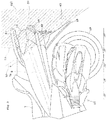
- Fig. 5 is an enlarged side view of a portion of a scooter according to Embodiment 3.
- the rear antenna 37 is attached to a rear slope 43 of the rear fender 15 by an anchor 45.
- the anchor 45 has a base seating surface 47 attached to the rear slope 43 of the rear fender 15, and an antenna seating surface 49 to which the rear antenna 37 is attached.
- the anchor 45 is formed such that, as seen from a side, an angle between the base seating surface 47 and antenna seating surface 49 causes the rear antenna 37 attached to the antenna seating surface 49 to be in an upright posture.
- a reinforcing member 53 is disposed on a front slope 51 which corresponds to an opposite side of the rear slope 43 of the rear fender 15.
- the reinforcing member 53 is formed of sheet metal having higher rigidity than the rear fender 15 formed of resin.
- the rear fender 15 is placed between the reinforcing member 53 and the anchor 45, and the anchor 45 is supported stably.
- the reinforcing member 53 may have an upper end thereof extending upward to be fastened together with the rear fender 15 to the vehicle body.
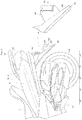
- Fig. 6 is an enlarged side view of a portion of a scooter according to Embodiment 4.
- the rear antenna 37 is attached to the fender 15 as in foregoing Embodiment 3.
- the rear fender 15 in this embodiment has, formed integral with the rear slope 43, an attaching portion 55 for attaching the rear antenna 37.
- This attaching portion 55 has a recess 57 formed for attaching the rear antenna 37.
- the recess 57 receives a back surface opposite to the electromagnetic wave emitting plane of the rear antenna 37, and a bottom surface of the rear antennas 37, and holds the rear antenna 37 in an upright posture.
- the rear antenna 37 can be attached rigidly to the rear fender 15. Further, the number of parts for attachment can be reduced, thereby to hold down cost.
- Fig. 7 is an enlarged side view of a portion of a scooter according to Embodiment 5.
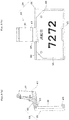
- Fig. 8 shows a license plate mounting bracket, in which (a) is a side view, and (b) is a front view.
- the rear antenna 37 is attached to the rear fender 15 through a license plate mounting bracket 59 which is formed of resin.
- the license plate mounting bracket 59 has a license plate attaching portion 61 and a rear antenna attaching portion 63 integrated together.
- the license plate attaching portion 61 has supporting projections 65 formed thereon which support an upper part and a lower part of the license plate 30.
- the rear antenna attaching portion 63 is formed to project from an upper middle position of the license plate attaching portion 61, and has a recess 67 formed therein for attaching the rear antenna 37.
- the rear antenna attaching portion 63 is formed to have an upper part thereof which assumes a position tilting slightly down rearward of the vehicle (rightward in Fig. 8 (a) and to the near side with respect to the plane of Fig. 8 (b) ) when the license plate attaching portion 61 is in an upright posture.
- the license plate mounting bracket 59 since the license plate attaching portion 61 is attached in a forwardly tilted posture to the rear fender 15, the rear antenna attaching portion 63 tilting rearward assumes an upright posture.
- the rear antenna 37 can be attached easily since the license plate 30 is attached to the license plate attaching portion 61 of the license plate mounting bracket 59, and the rear antenna 37 is attached to the rear antenna attaching portion 63.
- the rear antenna 37 can therefore be attached efficiently.
- An angle between the license plate attaching portion 59 and rear antenna attaching portion 63 of the license plate mounting bracket 59 is set to place the rear antenna 37 in an upright posture.
- the rear antenna 37 can therefore be attached in a posture well suited for vehicle-to-vehicle communication with rearward vehicles.
- a mounting position of the rear antenna 37 in each of Embodiments 1-5 described hereinbefore is, preferably, in a region rg1 (the hatched region) shown in Fig. 9 .
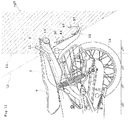
- Fig. 10 is a side view of a two-wheeled motor vehicle according to Embodiment 6.
- Embodiments 1-5 have been described taking a scooter as an example of two-wheeled motor vehicles, but this embodiment will be described taking what is called a naked type two-wheeled motor vehicle as a two-wheeled motor vehicle.
- the naked type refers to a two-wheeled motor vehicle with an uncovered engine and frame.
- This naked type two-wheeled motor vehicle has an attachment form similar to foregoing Embodiment 3. Specifically, a directional rear antenna 37 is attached to a lower portion of a rear slope 43 of a rear fender 15 through an anchor 69.
- the anchor 69 is formed to have such a shape that the antenna 37 assumes an upright posture when attached to the rear fender 15.
- a nondirectional front antenna 33 is erected at the other end of an anchor 73 having one end thereof attached to a lower bracket 71 of a front fork 21.
- the anchor 73 locates the front antenna 33 in front of and below a headlight 27.
- the front antenna 33 can be attached easily as in Embodiment 1, even if this is the naked type without the front cover 25. Lighting by the headlight 27 is not obstructed, and besides a forward emission of electromagnetic wave from the front antenna 33 is not obstructed by the headlight 27.
- the rear antenna 37 may be attached in the modes of foregoing Embodiments 3, 4 and 5. As in foregoing Embodiment 2, the rear antenna 37 may be disposed outward of the side covers 9.
- the rear antenna 37 is therefore not limited to the above-described mounting position in Fig. 10 , but may be disposed in any appropriate position within the region rg2.
- the anchor 73 may be attached to an upper portion of an inner tube 75 (upper tube) of the front fork 21, for example.
Landscapes
- Engineering & Computer Science (AREA)
- Remote Sensing (AREA)
- Mechanical Engineering (AREA)
- Computer Security & Cryptography (AREA)
- Radar, Positioning & Navigation (AREA)
- Support Of Aerials (AREA)
- Details Of Aerials (AREA)
- Fittings On The Vehicle Exterior For Carrying Loads, And Devices For Holding Or Mounting Articles (AREA)
- Variable-Direction Aerials And Aerial Arrays (AREA)
- Lighting Device Outwards From Vehicle And Optical Signal (AREA)
Claims (15)
- Ein Zweiradmotorfahrzeug, das dazu ausgebildet ist, eine Straße-Fahrzeug-Kommunikation mit straßenseitigen Einheiten und eine Fahrzeug-Fahrzeug-Kommunikation mit vorwärtigen Fahrzeugen und rückwärtigen Fahrzeugen auszuführen, wobei das Zweiradmotorfahrzeug folgende Merkmale aufweist:eine Frontantenne (33), die weiter vorne als ein Sitz (7) des Zweiradmotorfahrzeugs angeordnet ist; undeine Rückantenne (37), die weiter hinten als ein auf einer Rückseite des Sitzes (7) des Zweiradmotorfahrzeugs befindlicher Passagiersitz (7a) angeordnet ist, wobei sich die Rückantenne (37) in einer Draufsicht an einer Mitte quer zu einem Fahrzeugs befindet;wobeidie Frontantenne (33) aus einer ungerichteten Antenne besteht, bei der ein Emissionsmuster und eine Empfangsempfindlichkeit von elektromagnetischen Wellen um eine horizontale Ebene herum gleichförmig sind und die dazu ausgebildet ist, eine Straße-Fahrzeug-Kommunikation mit straßenseitigen Einheiten und eine Fahrzeug-Fahrzeug-Kommunikation mit vorwärtigen Fahrzeugen auszuführen; unddie Rückantenne (37) aus einer Richtantenne besteht, bei der ein Emissionsmuster und eine Empfangsempfindlichkeit von elektromagnetischen Wellen rückwärtig zu einem Fahrzeugkörper vorgespannt sind und die dazu ausgebildet ist, eine Fahrzeug-Fahrzeug-Kommunikation mit rückwärtigen Fahrzeugen auszuführen.
- Das Zweiradmotorfahrzeug gemäß Anspruch 1, bei dem die Rückantenne unter einer Rücklichteinheit (13) angebracht ist.
- Das Zweiradmotorfahrzeug gemäß Anspruch 2, bei dem die Rückantenne (37) innen von Seitenabdeckungen (9) angeordnet ist, die Bereiche um einen unteren Teil der Rücklichteinheit (13) herum abdecken.
- Zweiradmotorfahrzeug gemäß Anspruch 3, bei dem die Rückantenne (37) durch einen Anker (39, 41) an einer unteren Oberfläche der Rücklichteinheit (13) angebracht ist, die sich innen von den Seitenabdeckungen (9) befindet.
- Das Zweiradmotorfahrzeug gemäß Anspruch 2, bei dem die Rückantenne (37) außen von Seitenabdeckungen (9) angeordnet ist, die Bereiche um einen unteren Teil der Rücklichteinheit (13) abdecken.
- Das Zweiradmotorfahrzeug gemäß Anspruch 5, bei dem die Rückantenne (37) durch einen Anker (45) an einer Rückneigung (43) eines Rückkotflügels (15) angebracht ist.
- Das Zweiradmotorfahrzeug gemäß Anspruch 6, bei dem der Rückkotfllügel (15) ein Verstärkungsbauglied (53) aufweist, das entlang einer Frontneigung (51) desselben zum Tragen der Rückantenne (37) angebracht ist.
- Das Zweiradmotorfahrzeug gemäß Anspruch 6 oder 7, bei dem der Anker (45) derart gebildet ist, dass ein Winkel zwischen einer Basissitzoberfläche (47), die an der Rückneigung (43) des Rückkotflügels (15) angebracht ist, und einer Antennenanbringungsoberfläche (49), an der die Rückantenne (37) angebracht ist, bewirkt, dass die Rückantenne (37) bei Betrachtung von einer Seite in einer aufrechten Stellung ist.
- Das Zweiradmotorfahrzeug gemäß Anspruch 5, bei dem:der Rückkotflügel (15) einen einstückig mit der Rückneigung (43) gebildeten Anbringungsabschnitt (63) zum Anbringen der Rückantenne (37) aufweist; unddie Rückantenne (37) an dem Anbringungsabschnitt (63) angebracht ist.
- Das Zweiradmotorfahrzeug gemäß Anspruch 5, bei dem die Rückantenne (37) dahingehend angebracht ist, höher zu sein als ein Nummernschild (30).
- Das Zweiradmotorfahrzeug gemäß Anspruch 10, bei dem das Nummernschild (30) durch eine Nummernschildmontierspange (59) angebracht ist, die einen Nummernschildanbringungsabschnitt (61), an dem das Nummernschild (30) angebracht, und einen Rückantennenanbringungsabschnitt (63), an dem die Rückantenne (37) angebracht ist, einstückig miteinander aufweist.
- Das Zweiradmotorfahrzeug gemäß Anspruch 11, bei dem die Nummernschildmontierspange (59) derart gebildet ist, dass ein Winkel zwischen dem Nummernschildanbringungsabschnitt (61) und dem Rückantennenanbringungsabschnitt (63) bewirkt, dass die Rückantenne (37) bei Betrachtung von einer Seite in einer aufrechten Stellung ist.
- Das Zweiradmotorfahrzeug gemäß einem der Ansprüche 2 bis 6, bei dem die Rückantenne (37) in einem rückwärtigen Bereich angebracht ist, der durch eine vertikale Linie markiert ist, die von einem Rückende eines Sitzrahmens (5), der fortlaufend mit und rückwärtig zu einem Hauptrahmen (3) ist, und einer erweiterten Linie entlang einer Rückneigung (43) eines Rückkotflügels (15) gezeichnet ist.
- Das Zweiradmotorfahrzeug gemäß einem der Ansprüche 1 bis 13, bei dem die Frontantenne (33) durch einen Anker (35) an einer Halterung (31) angebracht ist, die sich von einem Hauptrahmen (3) weiter vorn als ein Kopfrohr (1) zum Befestigen einer Frontabdeckung (25) erstreckt.
- Das Zweiradmotorfahrzeug gemäß einem der Ansprüche 1 bis 13, bei dem die Frontantenne (33) durch einen Anker (37) an einer Vordergabel (21) angebracht ist.
Applications Claiming Priority (2)
| Application Number | Priority Date | Filing Date | Title |
|---|---|---|---|
| JP2013045435 | 2013-03-07 | ||
| PCT/JP2014/054955 WO2014136658A1 (ja) | 2013-03-07 | 2014-02-27 | 自動二輪車 |
Publications (3)
| Publication Number | Publication Date |
|---|---|
| EP2965979A1 EP2965979A1 (de) | 2016-01-13 |
| EP2965979A4 EP2965979A4 (de) | 2016-01-13 |
| EP2965979B1 true EP2965979B1 (de) | 2019-01-30 |
Family
ID=51491177
Family Applications (1)
| Application Number | Title | Priority Date | Filing Date |
|---|---|---|---|
| EP14760526.5A Active EP2965979B1 (de) | 2013-03-07 | 2014-02-27 | Zweirädriges kraftrad |
Country Status (4)
| Country | Link |
|---|---|
| US (1) | US9893415B2 (de) |
| EP (1) | EP2965979B1 (de) |
| JP (1) | JP6007311B2 (de) |
| WO (1) | WO2014136658A1 (de) |
Families Citing this family (17)
| Publication number | Priority date | Publication date | Assignee | Title |
|---|---|---|---|---|
| DE102015201641A1 (de) * | 2015-01-30 | 2016-08-04 | Bayerische Motoren Werke Aktiengesellschaft | Applikationsgesteuertes Geo-Beamforming |
| EP3574550B1 (de) * | 2016-07-12 | 2022-08-31 | PSA Automobiles SA | Montage von elektronischen antennenbuchsen auf einer heckklappe eines fahrzeugs |
| JP6608976B2 (ja) * | 2018-01-24 | 2019-11-20 | ヤマハ発動機株式会社 | 指向性アンテナ |
| DE112018007317B4 (de) * | 2018-03-20 | 2023-03-02 | Honda Motor Co., Ltd. | Fahrzeug vom Grätschsitz-Typ |
| JP7078710B2 (ja) * | 2018-03-29 | 2022-05-31 | 本田技研工業株式会社 | 鞍乗型車両 |
| WO2019224960A1 (ja) | 2018-05-23 | 2019-11-28 | 本田技研工業株式会社 | 鞍乗型車両 |
| JP7066839B2 (ja) * | 2018-05-23 | 2022-05-13 | 本田技研工業株式会社 | 鞍乗型車両 |
| WO2020045390A1 (ja) * | 2018-08-27 | 2020-03-05 | ヤマハ発動機株式会社 | 車車間通信用アンテナ搭載リーン車両 |
| JP7191963B2 (ja) * | 2018-08-27 | 2022-12-19 | ヤマハ発動機株式会社 | 車車間通信用アンテナ搭載リーン車両、及びリーン車両に搭載されるように構成された車車間通信用アンテナ |
| JP6929468B2 (ja) * | 2018-08-27 | 2021-09-01 | ヤマハ発動機株式会社 | 車車間通信用アンテナ装置及びリーン車両 |
| WO2020045252A1 (ja) | 2018-08-27 | 2020-03-05 | ヤマハ発動機株式会社 | V2x通信用アンテナ搭載リーン車両 |
| WO2020066352A1 (ja) | 2018-09-28 | 2020-04-02 | 本田技研工業株式会社 | 鞍乗型車両 |
| JP7216743B2 (ja) * | 2018-12-21 | 2023-02-01 | カワサキモータース株式会社 | 鞍乗型車両 |
| JP6777170B2 (ja) * | 2019-01-11 | 2020-10-28 | スズキ株式会社 | 自動二・三輪車 |
| JP6705514B2 (ja) * | 2019-01-11 | 2020-06-03 | スズキ株式会社 | 自動二・三輪車 |
| CN115279654B (zh) * | 2020-02-04 | 2024-03-26 | 印度摩托车国际有限公司 | 用于摩托车组件的电子部件组件 |
| IT202100017471A1 (it) * | 2021-07-02 | 2023-01-02 | Piaggio & C Spa | Veicolo a sella cavalcabile dotato di unità di rilevamento |
Citations (4)
| Publication number | Priority date | Publication date | Assignee | Title |
|---|---|---|---|---|
| US20020003488A1 (en) * | 2000-02-13 | 2002-01-10 | Hexagon System Engineering Ltd. | Vehicle communication network |
| US20020003501A1 (en) * | 2000-04-03 | 2002-01-10 | Kazumitsu Kushida | Antenna disposition structure for motorcycle |
| EP1905682A1 (de) * | 2006-09-26 | 2008-04-02 | HONDA MOTOR CO., Ltd. | Antennenbefestigungsstruktur für ein Motorrad |
| DE102010028881A1 (de) * | 2009-06-03 | 2010-12-09 | Continental Teves Ag & Co. Ohg | Fahrzeugantennenvorrichtung mit horizontaler Hauptstrahlrichtung |
Family Cites Families (12)
| Publication number | Priority date | Publication date | Assignee | Title |
|---|---|---|---|---|
| JP2005108008A (ja) * | 2003-09-30 | 2005-04-21 | Honda Motor Co Ltd | 自動二輪車用etcシステム |
| US6873297B1 (en) * | 2003-11-13 | 2005-03-29 | Mobile Marks, Inc. | License plate frame with antenna |
| JP4390203B2 (ja) | 2004-09-30 | 2009-12-24 | 本田技研工業株式会社 | 自動二輪車のナビゲーション装置 |
| JP4386818B2 (ja) * | 2004-10-07 | 2009-12-16 | 本田技研工業株式会社 | 小型車両の通信手段配置構造 |
| JP4467525B2 (ja) | 2005-01-21 | 2010-05-26 | 富士フイルム株式会社 | フイルム巻取装置及び巻取方法 |
| JP2006232181A (ja) | 2005-02-25 | 2006-09-07 | Toshiba Corp | 自動二輪車用の車載装置 |
| JP4989272B2 (ja) | 2007-03-28 | 2012-08-01 | 本田技研工業株式会社 | 自動二輪車用アンテナ収容構造 |
| JP5192995B2 (ja) * | 2008-11-14 | 2013-05-08 | 本田技研工業株式会社 | 自動二輪車の盗難対策装置 |
| JP5392124B2 (ja) | 2010-02-03 | 2014-01-22 | 株式会社デンソー | 車載無線通信システム |
| JP2011225160A (ja) * | 2010-04-22 | 2011-11-10 | Suzuki Motor Corp | 自動二輪車の通信アンテナ配置構造 |
| JP5427735B2 (ja) * | 2010-08-31 | 2014-02-26 | 本田技研工業株式会社 | 鞍乗り型車両 |
| JP5656923B2 (ja) | 2012-06-18 | 2015-01-21 | 本田技研工業株式会社 | 自動二輪車の盗難対策装置 |
-
2014
- 2014-02-27 JP JP2015504269A patent/JP6007311B2/ja active Active
- 2014-02-27 US US14/772,756 patent/US9893415B2/en active Active
- 2014-02-27 EP EP14760526.5A patent/EP2965979B1/de active Active
- 2014-02-27 WO PCT/JP2014/054955 patent/WO2014136658A1/ja not_active Ceased
Patent Citations (4)
| Publication number | Priority date | Publication date | Assignee | Title |
|---|---|---|---|---|
| US20020003488A1 (en) * | 2000-02-13 | 2002-01-10 | Hexagon System Engineering Ltd. | Vehicle communication network |
| US20020003501A1 (en) * | 2000-04-03 | 2002-01-10 | Kazumitsu Kushida | Antenna disposition structure for motorcycle |
| EP1905682A1 (de) * | 2006-09-26 | 2008-04-02 | HONDA MOTOR CO., Ltd. | Antennenbefestigungsstruktur für ein Motorrad |
| DE102010028881A1 (de) * | 2009-06-03 | 2010-12-09 | Continental Teves Ag & Co. Ohg | Fahrzeugantennenvorrichtung mit horizontaler Hauptstrahlrichtung |
Also Published As
| Publication number | Publication date |
|---|---|
| EP2965979A1 (de) | 2016-01-13 |
| US9893415B2 (en) | 2018-02-13 |
| WO2014136658A1 (ja) | 2014-09-12 |
| EP2965979A4 (de) | 2016-01-13 |
| JP6007311B2 (ja) | 2016-10-12 |
| US20160013545A1 (en) | 2016-01-14 |
| JPWO2014136658A1 (ja) | 2017-02-09 |
Similar Documents
| Publication | Publication Date | Title |
|---|---|---|
| US9893415B2 (en) | Two-wheeled motor vehicle | |
| US8317212B2 (en) | Motorcycle including bendable rear fender | |
| JP2019048554A (ja) | 自動二輪車 | |
| JPWO2019224959A1 (ja) | 鞍乗型車両 | |
| US20210175614A1 (en) | V2x communication antenna-mounted leaning vehicle | |
| US11588229B2 (en) | Straddle type vehicle | |
| EP2180332A1 (de) | Motorrad | |
| EP3838728A1 (de) | Grätschsitzfahrzeug | |
| US20220297783A1 (en) | Straddled vehicle | |
| JP2012232657A (ja) | 鞍乗型車両 | |
| EP2980920B1 (de) | Motorrad | |
| JP6346292B2 (ja) | 鞍乗型車両 | |
| JP2025002931A (ja) | 車両前部構造 | |
| JP7191963B2 (ja) | 車車間通信用アンテナ搭載リーン車両、及びリーン車両に搭載されるように構成された車車間通信用アンテナ | |
| US12559191B2 (en) | Rideable saddle vehicle provided with detection unit | |
| JP7183279B2 (ja) | 車車間通信用アンテナ搭載リーン車両、及びリーン車両に搭載されるように構成された車車間通信用アンテナ | |
| CN209921164U (zh) | 一种载重汽车尾灯组合安装装置 | |
| JPWO2020045391A1 (ja) | 車車間通信用アンテナ搭載リーン車両、及びリーン車両に搭載されるように構成された車車間通信用アンテナ | |
| US20060077111A1 (en) | Communication device for small vehicles | |
| CN212073861U (zh) | 一种后尾灯防护机构 | |
| CN111038626B (zh) | 骑乘型车辆 | |
| EP3689723B1 (de) | Kennzeichenleuchte | |
| JP2025002932A (ja) | 車両前部構造 | |
| JPH03204381A (ja) | 車両のパイプ類配索装置 | |
| JP2008126676A (ja) | 自動2輪車に対する車載側アンテナの設置構造 |
Legal Events
| Date | Code | Title | Description |
|---|---|---|---|
| PUAI | Public reference made under article 153(3) epc to a published international application that has entered the european phase |
Free format text: ORIGINAL CODE: 0009012 |
|
| 17P | Request for examination filed |
Effective date: 20150904 |
|
| A4 | Supplementary search report drawn up and despatched |
Effective date: 20151209 |
|
| AK | Designated contracting states |
Kind code of ref document: A1 Designated state(s): AL AT BE BG CH CY CZ DE DK EE ES FI FR GB GR HR HU IE IS IT LI LT LU LV MC MK MT NL NO PL PT RO RS SE SI SK SM TR |
|
| AX | Request for extension of the european patent |
Extension state: BA ME |
|
| DAX | Request for extension of the european patent (deleted) | ||
| 17Q | First examination report despatched |
Effective date: 20160726 |
|
| STAA | Information on the status of an ep patent application or granted ep patent |
Free format text: STATUS: EXAMINATION IS IN PROGRESS |
|
| GRAP | Despatch of communication of intention to grant a patent |
Free format text: ORIGINAL CODE: EPIDOSNIGR1 |
|
| STAA | Information on the status of an ep patent application or granted ep patent |
Free format text: STATUS: GRANT OF PATENT IS INTENDED |
|
| INTG | Intention to grant announced |
Effective date: 20180803 |
|
| RAP1 | Party data changed (applicant data changed or rights of an application transferred) |
Owner name: YAMAHA HATSUDOKI KABUSHIKI KAISHA |
|
| RIN1 | Information on inventor provided before grant (corrected) |
Inventor name: HASHIMOTO, YASUSHI |
|
| GRAS | Grant fee paid |
Free format text: ORIGINAL CODE: EPIDOSNIGR3 |
|
| GRAA | (expected) grant |
Free format text: ORIGINAL CODE: 0009210 |
|
| STAA | Information on the status of an ep patent application or granted ep patent |
Free format text: STATUS: THE PATENT HAS BEEN GRANTED |
|
| AK | Designated contracting states |
Kind code of ref document: B1 Designated state(s): AL AT BE BG CH CY CZ DE DK EE ES FI FR GB GR HR HU IE IS IT LI LT LU LV MC MK MT NL NO PL PT RO RS SE SI SK SM TR |
|
| REG | Reference to a national code |
Ref country code: GB Ref legal event code: FG4D |
|
| REG | Reference to a national code |
Ref country code: CH Ref legal event code: EP |
|
| REG | Reference to a national code |
Ref country code: AT Ref legal event code: REF Ref document number: 1093031 Country of ref document: AT Kind code of ref document: T Effective date: 20190215 |
|
| REG | Reference to a national code |
Ref country code: IE Ref legal event code: FG4D |
|
| REG | Reference to a national code |
Ref country code: DE Ref legal event code: R096 Ref document number: 602014040390 Country of ref document: DE |
|
| REG | Reference to a national code |
Ref country code: LT Ref legal event code: MG4D |
|
| REG | Reference to a national code |
Ref country code: NL Ref legal event code: MP Effective date: 20190130 |
|
| PG25 | Lapsed in a contracting state [announced via postgrant information from national office to epo] |
Ref country code: ES Free format text: LAPSE BECAUSE OF FAILURE TO SUBMIT A TRANSLATION OF THE DESCRIPTION OR TO PAY THE FEE WITHIN THE PRESCRIBED TIME-LIMIT Effective date: 20190130 Ref country code: NL Free format text: LAPSE BECAUSE OF FAILURE TO SUBMIT A TRANSLATION OF THE DESCRIPTION OR TO PAY THE FEE WITHIN THE PRESCRIBED TIME-LIMIT Effective date: 20190130 Ref country code: PT Free format text: LAPSE BECAUSE OF FAILURE TO SUBMIT A TRANSLATION OF THE DESCRIPTION OR TO PAY THE FEE WITHIN THE PRESCRIBED TIME-LIMIT Effective date: 20190530 Ref country code: SE Free format text: LAPSE BECAUSE OF FAILURE TO SUBMIT A TRANSLATION OF THE DESCRIPTION OR TO PAY THE FEE WITHIN THE PRESCRIBED TIME-LIMIT Effective date: 20190130 Ref country code: FI Free format text: LAPSE BECAUSE OF FAILURE TO SUBMIT A TRANSLATION OF THE DESCRIPTION OR TO PAY THE FEE WITHIN THE PRESCRIBED TIME-LIMIT Effective date: 20190130 Ref country code: NO Free format text: LAPSE BECAUSE OF FAILURE TO SUBMIT A TRANSLATION OF THE DESCRIPTION OR TO PAY THE FEE WITHIN THE PRESCRIBED TIME-LIMIT Effective date: 20190430 Ref country code: PL Free format text: LAPSE BECAUSE OF FAILURE TO SUBMIT A TRANSLATION OF THE DESCRIPTION OR TO PAY THE FEE WITHIN THE PRESCRIBED TIME-LIMIT Effective date: 20190130 Ref country code: LT Free format text: LAPSE BECAUSE OF FAILURE TO SUBMIT A TRANSLATION OF THE DESCRIPTION OR TO PAY THE FEE WITHIN THE PRESCRIBED TIME-LIMIT Effective date: 20190130 |
|
| REG | Reference to a national code |
Ref country code: AT Ref legal event code: MK05 Ref document number: 1093031 Country of ref document: AT Kind code of ref document: T Effective date: 20190130 |
|
| PG25 | Lapsed in a contracting state [announced via postgrant information from national office to epo] |
Ref country code: IS Free format text: LAPSE BECAUSE OF FAILURE TO SUBMIT A TRANSLATION OF THE DESCRIPTION OR TO PAY THE FEE WITHIN THE PRESCRIBED TIME-LIMIT Effective date: 20190530 Ref country code: BG Free format text: LAPSE BECAUSE OF FAILURE TO SUBMIT A TRANSLATION OF THE DESCRIPTION OR TO PAY THE FEE WITHIN THE PRESCRIBED TIME-LIMIT Effective date: 20190430 Ref country code: HR Free format text: LAPSE BECAUSE OF FAILURE TO SUBMIT A TRANSLATION OF THE DESCRIPTION OR TO PAY THE FEE WITHIN THE PRESCRIBED TIME-LIMIT Effective date: 20190130 Ref country code: GR Free format text: LAPSE BECAUSE OF FAILURE TO SUBMIT A TRANSLATION OF THE DESCRIPTION OR TO PAY THE FEE WITHIN THE PRESCRIBED TIME-LIMIT Effective date: 20190501 Ref country code: LV Free format text: LAPSE BECAUSE OF FAILURE TO SUBMIT A TRANSLATION OF THE DESCRIPTION OR TO PAY THE FEE WITHIN THE PRESCRIBED TIME-LIMIT Effective date: 20190130 Ref country code: RS Free format text: LAPSE BECAUSE OF FAILURE TO SUBMIT A TRANSLATION OF THE DESCRIPTION OR TO PAY THE FEE WITHIN THE PRESCRIBED TIME-LIMIT Effective date: 20190130 |
|
| REG | Reference to a national code |
Ref country code: CH Ref legal event code: PL |
|
| PG25 | Lapsed in a contracting state [announced via postgrant information from national office to epo] |
Ref country code: CZ Free format text: LAPSE BECAUSE OF FAILURE TO SUBMIT A TRANSLATION OF THE DESCRIPTION OR TO PAY THE FEE WITHIN THE PRESCRIBED TIME-LIMIT Effective date: 20190130 Ref country code: RO Free format text: LAPSE BECAUSE OF FAILURE TO SUBMIT A TRANSLATION OF THE DESCRIPTION OR TO PAY THE FEE WITHIN THE PRESCRIBED TIME-LIMIT Effective date: 20190130 Ref country code: DK Free format text: LAPSE BECAUSE OF FAILURE TO SUBMIT A TRANSLATION OF THE DESCRIPTION OR TO PAY THE FEE WITHIN THE PRESCRIBED TIME-LIMIT Effective date: 20190130 Ref country code: EE Free format text: LAPSE BECAUSE OF FAILURE TO SUBMIT A TRANSLATION OF THE DESCRIPTION OR TO PAY THE FEE WITHIN THE PRESCRIBED TIME-LIMIT Effective date: 20190130 Ref country code: MC Free format text: LAPSE BECAUSE OF FAILURE TO SUBMIT A TRANSLATION OF THE DESCRIPTION OR TO PAY THE FEE WITHIN THE PRESCRIBED TIME-LIMIT Effective date: 20190130 Ref country code: LU Free format text: LAPSE BECAUSE OF NON-PAYMENT OF DUE FEES Effective date: 20190227 Ref country code: SK Free format text: LAPSE BECAUSE OF FAILURE TO SUBMIT A TRANSLATION OF THE DESCRIPTION OR TO PAY THE FEE WITHIN THE PRESCRIBED TIME-LIMIT Effective date: 20190130 Ref country code: AL Free format text: LAPSE BECAUSE OF FAILURE TO SUBMIT A TRANSLATION OF THE DESCRIPTION OR TO PAY THE FEE WITHIN THE PRESCRIBED TIME-LIMIT Effective date: 20190130 |
|
| REG | Reference to a national code |
Ref country code: DE Ref legal event code: R097 Ref document number: 602014040390 Country of ref document: DE |
|
| REG | Reference to a national code |
Ref country code: BE Ref legal event code: MM Effective date: 20190228 |
|
| REG | Reference to a national code |
Ref country code: IE Ref legal event code: MM4A |
|
| PG25 | Lapsed in a contracting state [announced via postgrant information from national office to epo] |
Ref country code: SM Free format text: LAPSE BECAUSE OF FAILURE TO SUBMIT A TRANSLATION OF THE DESCRIPTION OR TO PAY THE FEE WITHIN THE PRESCRIBED TIME-LIMIT Effective date: 20190130 |
|
| PLBE | No opposition filed within time limit |
Free format text: ORIGINAL CODE: 0009261 |
|
| STAA | Information on the status of an ep patent application or granted ep patent |
Free format text: STATUS: NO OPPOSITION FILED WITHIN TIME LIMIT |
|
| GBPC | Gb: european patent ceased through non-payment of renewal fee |
Effective date: 20190430 |
|
| PG25 | Lapsed in a contracting state [announced via postgrant information from national office to epo] |
Ref country code: LI Free format text: LAPSE BECAUSE OF NON-PAYMENT OF DUE FEES Effective date: 20190228 Ref country code: AT Free format text: LAPSE BECAUSE OF FAILURE TO SUBMIT A TRANSLATION OF THE DESCRIPTION OR TO PAY THE FEE WITHIN THE PRESCRIBED TIME-LIMIT Effective date: 20190130 Ref country code: CH Free format text: LAPSE BECAUSE OF NON-PAYMENT OF DUE FEES Effective date: 20190228 |
|
| 26N | No opposition filed |
Effective date: 20191031 |
|
| PG25 | Lapsed in a contracting state [announced via postgrant information from national office to epo] |
Ref country code: GB Free format text: LAPSE BECAUSE OF NON-PAYMENT OF DUE FEES Effective date: 20190430 Ref country code: IE Free format text: LAPSE BECAUSE OF NON-PAYMENT OF DUE FEES Effective date: 20190227 |
|
| PG25 | Lapsed in a contracting state [announced via postgrant information from national office to epo] |
Ref country code: BE Free format text: LAPSE BECAUSE OF NON-PAYMENT OF DUE FEES Effective date: 20190228 Ref country code: SI Free format text: LAPSE BECAUSE OF FAILURE TO SUBMIT A TRANSLATION OF THE DESCRIPTION OR TO PAY THE FEE WITHIN THE PRESCRIBED TIME-LIMIT Effective date: 20190130 |
|
| PG25 | Lapsed in a contracting state [announced via postgrant information from national office to epo] |
Ref country code: TR Free format text: LAPSE BECAUSE OF FAILURE TO SUBMIT A TRANSLATION OF THE DESCRIPTION OR TO PAY THE FEE WITHIN THE PRESCRIBED TIME-LIMIT Effective date: 20190130 |
|
| PG25 | Lapsed in a contracting state [announced via postgrant information from national office to epo] |
Ref country code: MT Free format text: LAPSE BECAUSE OF NON-PAYMENT OF DUE FEES Effective date: 20190227 |
|
| PG25 | Lapsed in a contracting state [announced via postgrant information from national office to epo] |
Ref country code: CY Free format text: LAPSE BECAUSE OF FAILURE TO SUBMIT A TRANSLATION OF THE DESCRIPTION OR TO PAY THE FEE WITHIN THE PRESCRIBED TIME-LIMIT Effective date: 20190130 |
|
| PG25 | Lapsed in a contracting state [announced via postgrant information from national office to epo] |
Ref country code: HU Free format text: LAPSE BECAUSE OF FAILURE TO SUBMIT A TRANSLATION OF THE DESCRIPTION OR TO PAY THE FEE WITHIN THE PRESCRIBED TIME-LIMIT; INVALID AB INITIO Effective date: 20140227 |
|
| PG25 | Lapsed in a contracting state [announced via postgrant information from national office to epo] |
Ref country code: MK Free format text: LAPSE BECAUSE OF FAILURE TO SUBMIT A TRANSLATION OF THE DESCRIPTION OR TO PAY THE FEE WITHIN THE PRESCRIBED TIME-LIMIT Effective date: 20190130 |
|
| P01 | Opt-out of the competence of the unified patent court (upc) registered |
Effective date: 20230527 |
|
| PGFP | Annual fee paid to national office [announced via postgrant information from national office to epo] |
Ref country code: DE Payment date: 20260218 Year of fee payment: 13 |
|
| PGFP | Annual fee paid to national office [announced via postgrant information from national office to epo] |
Ref country code: IT Payment date: 20260224 Year of fee payment: 13 |
|
| PGFP | Annual fee paid to national office [announced via postgrant information from national office to epo] |
Ref country code: FR Payment date: 20260218 Year of fee payment: 13 |