EP2966342A1 - Module d'éclairage pour projecteur automobile avec positionnement entre dissipateur thermique et reflecteur/lentille - Google Patents
Module d'éclairage pour projecteur automobile avec positionnement entre dissipateur thermique et reflecteur/lentille Download PDFInfo
- Publication number
- EP2966342A1 EP2966342A1 EP15173917.4A EP15173917A EP2966342A1 EP 2966342 A1 EP2966342 A1 EP 2966342A1 EP 15173917 A EP15173917 A EP 15173917A EP 2966342 A1 EP2966342 A1 EP 2966342A1
- Authority
- EP
- European Patent Office
- Prior art keywords
- heat sink
- support
- lens
- module
- light module
- Prior art date
- Legal status (The legal status is an assumption and is not a legal conclusion. Google has not performed a legal analysis and makes no representation as to the accuracy of the status listed.)
- Granted
Links
Images


Classifications
-
- F—MECHANICAL ENGINEERING; LIGHTING; HEATING; WEAPONS; BLASTING
- F21—LIGHTING
- F21S—NON-PORTABLE LIGHTING DEVICES; SYSTEMS THEREOF; VEHICLE LIGHTING DEVICES SPECIALLY ADAPTED FOR VEHICLE EXTERIORS
- F21S45/00—Arrangements within vehicle lighting devices specially adapted for vehicle exteriors, for purposes other than emission or distribution of light
- F21S45/40—Cooling of lighting devices
- F21S45/47—Passive cooling, e.g. using fins, thermal conductive elements or openings
-
- F—MECHANICAL ENGINEERING; LIGHTING; HEATING; WEAPONS; BLASTING
- F21—LIGHTING
- F21S—NON-PORTABLE LIGHTING DEVICES; SYSTEMS THEREOF; VEHICLE LIGHTING DEVICES SPECIALLY ADAPTED FOR VEHICLE EXTERIORS
- F21S41/00—Illuminating devices specially adapted for vehicle exteriors, e.g. headlamps
- F21S41/10—Illuminating devices specially adapted for vehicle exteriors, e.g. headlamps characterised by the light source
- F21S41/19—Attachment of light sources or lamp holders
- F21S41/192—Details of lamp holders, terminals or connectors
-
- F—MECHANICAL ENGINEERING; LIGHTING; HEATING; WEAPONS; BLASTING
- F21—LIGHTING
- F21S—NON-PORTABLE LIGHTING DEVICES; SYSTEMS THEREOF; VEHICLE LIGHTING DEVICES SPECIALLY ADAPTED FOR VEHICLE EXTERIORS
- F21S41/00—Illuminating devices specially adapted for vehicle exteriors, e.g. headlamps
- F21S41/20—Illuminating devices specially adapted for vehicle exteriors, e.g. headlamps characterised by refractors, transparent cover plates, light guides or filters
- F21S41/29—Attachment thereof
- F21S41/295—Attachment thereof specially adapted to projection lenses
-
- F—MECHANICAL ENGINEERING; LIGHTING; HEATING; WEAPONS; BLASTING
- F21—LIGHTING
- F21S—NON-PORTABLE LIGHTING DEVICES; SYSTEMS THEREOF; VEHICLE LIGHTING DEVICES SPECIALLY ADAPTED FOR VEHICLE EXTERIORS
- F21S41/00—Illuminating devices specially adapted for vehicle exteriors, e.g. headlamps
- F21S41/30—Illuminating devices specially adapted for vehicle exteriors, e.g. headlamps characterised by reflectors
- F21S41/39—Attachment thereof
-
- F—MECHANICAL ENGINEERING; LIGHTING; HEATING; WEAPONS; BLASTING
- F21—LIGHTING
- F21S—NON-PORTABLE LIGHTING DEVICES; SYSTEMS THEREOF; VEHICLE LIGHTING DEVICES SPECIALLY ADAPTED FOR VEHICLE EXTERIORS
- F21S45/00—Arrangements within vehicle lighting devices specially adapted for vehicle exteriors, for purposes other than emission or distribution of light
- F21S45/40—Cooling of lighting devices
- F21S45/49—Attachment of the cooling means
-
- F—MECHANICAL ENGINEERING; LIGHTING; HEATING; WEAPONS; BLASTING
- F21—LIGHTING
- F21S—NON-PORTABLE LIGHTING DEVICES; SYSTEMS THEREOF; VEHICLE LIGHTING DEVICES SPECIALLY ADAPTED FOR VEHICLE EXTERIORS
- F21S41/00—Illuminating devices specially adapted for vehicle exteriors, e.g. headlamps
- F21S41/30—Illuminating devices specially adapted for vehicle exteriors, e.g. headlamps characterised by reflectors
- F21S41/32—Optical layout thereof
- F21S41/321—Optical layout thereof the reflector being a surface of revolution or a planar surface, e.g. truncated
Definitions
- the invention relates to the field of lighting, more particularly to automotive lighting.
- the invention relates to a projector lighting module for a motor vehicle.
- the published patent document EP 2 428 725 A2 discloses a car projector lighting module.
- the lighting module in question comprises a light-emitting diode-type light source (LED) mounted on a plate disposed on a cooling radiator of said diode.
- the module also comprises a first reflective surface in the form of a half-shell and able to reflect the rays emitted by the light source towards a second reflective surface, called a bending surface, with a cutting edge of the illumination beam.
- the lighting module also includes a lens disposed at the front of the second reflective surface. The rays reflected by the first reflective surface and which pass in front of the cutting edge of the pious meet the lens and are deflected by it.
- rays meeting the second reflecting surface instead of meeting the lens at its lower part with a lower incidence angle than the previous rays, are reflected towards the upper part of the lens with a substantially identical angle of incidence. These rays are then deflected by the lens towards the bottom of the beam instead of being deflected upwards, thus achieving a typical cutoff of a lighting beam of the "code" type or even dipped beam.
- a main part serves as support for the lens, the reflective surface in the form of a half-shell and the folder. This piece is then attached to the radiator. The latter directly supports the plate with the light source.
- the longitudinal positioning between the main part and the radiator is effected by means of eyelets on the main part cooperating by engagement with drums on the radiator.
- the main part comprises abutment surfaces cooperating directly with the radiator for vertical positioning.
- This teaching is interesting in that the main piece ensures a precise relative positioning between the lens, the reflective surface, the folder and the radiator. Indeed, the lens is fully supported by the main piece. In the case of bulky and heavy lenses, this can pose some difficulties in terms of stability of the lens especially in the presence of vibrations. In addition, the main piece is a complicated piece that may also have some manufacturing tolerances potentially affecting the accuracy of the assembly.
- the object of the invention is to overcome at least one of the drawbacks of the prior art, more particularly of the aforementioned prior art. More particularly, the invention aims to provide a lighting module whose implementation is simplified while maintaining a high level of accuracy between the lens and the rest of the module, such as the reflecting surface and the source or sources bright.
- the subject of the invention is a light module, in particular for lighting and / or signaling, for a motor vehicle, comprising: at least one light source; a heat sink adapted to dissipate the heat produced by said source or sources; a reflective surface capable of reflecting the rays of the light source or sources; a lens adapted to deflect the rays from the reflecting surface to form a light beam along an optical axis of the module; a support for the lens and the reflective surface, said support being mounted on the heat sink; remarkable in that the heat sink and / or the support comprises at least one, preferably at least two bosses in contact with each other of the dissipator and the support so as to maintain a predetermined distance between the dissipator and the support.
- the boss or bosses are directed vertically.
- the boss or bosses are located, in the direction of the optical axis, between the reflecting surface and the lens.
- the lens comprises at least one, preferably at least two lower fastening tabs extending vertically through the support.
- the support comprises a notch, the lower fastening tab or tabs extending through this notch.
- the or each of the fixing lugs cooperates by engagement with the heat sink, said engagement preferably having a vertical clearance of less than 0.5 mm, more preferably a vertical clearance of less than 0.1 mm, more preferably still a vertical tightening.
- the heat sink comprises a rear portion supporting the light source or sources and a front portion, the boss or bosses being on the front portion.
- the front portion of the heat sink is against the bottom portion of said dissipator.
- the heat sink has a stepped profile, the front portion forming a first step of said staircase and the rear portion forming a second step, higher, said staircase.
- the support extends along the respective upper surfaces of the front and rear portions of the heat sink, the lens being in vertical support on said support.
- the engagement between the lens and the heat sink is on the front portion of said dissipator.
- the front portion of the heat sink comprises at least one, preferably at least two tabs extending forward and cooperating by engagement with an opening in the or the lugs of the lens, respectively.
- the or each leg of the heat sink forms a stop in the direction of the optical axis for the corresponding fixing lug of the lens.
- the or each leg of the heat sink has a profile forming, in the direction of the optical axis, a projection.
- the or each of the legs of the heat sink comprises at least one rib extending in the direction of the axis. optical, so as to achieve a clamping engagement with the corresponding fixing lug of the lens.
- At least two of the bosses are arranged laterally on either side of the optical axis of the module.
- the reflecting surface and the support are a single piece.
- the reflecting surface may be formed on a cavity of the support, for example by metallization of this cavity, if necessary the reflecting surface and the support forms the same part.
- the support comprises positioning means with respect to the heat sink and in the direction of the optical axis.
- the positioning means of the support in the direction of the optical axis cooperate with a plate supporting the light source or sources, said plate being disposed on the rear portion of the heat sink.
- the light source (s) are of the electroluminescence diode type.
- the plate comprises a printed circuit, preferably with a connector, said circuit being connected to the light source or sources for their power supply.
- the means for positioning the support in the direction of the optical axis comprise at least one, preferably at least two lugs, each of the lugs protruding vertically downwards in a cavity of the heat sink, said abutment or each of said abutments cooperating by contact with the edge of an orifice in the plate.
- the heat sink is made of metal material and / or molded plastic, the or at least two of the bosses being integral with the dissipator and made by molding said dissipator.
- the invention also relates to a light device for a motor vehicle, comprising a housing and at least one light module, remarkable in that the module or at least one of the modules is in accordance with the invention.
- the measures of the invention are interesting in that they make it possible to easily and economically achieve a lighting module with a precise positioning of the lens relative to the reflecting surface and / or the light source or sources.
- the figure 1 is a perspective representation of a lighting module according to the invention.
- This lighting module can be mounted in a motor vehicle headlight. In this case, this module produces a cut-off lighting beam such as for a lighting function of the "code" type or even dipped beam.
- the lighting module 2 illustrated at figure 1 comprises, essentially a radiator, or heat sink, 6 on which is arranged a plate 16 provided with one or more light sources 12, preferably of the electroluminescence diode type.
- a support 4 shown in transparency and extending over the entire length of the module is disposed on the radiator 6.
- the support is in contact with a lens 8 and comprises a reflecting surface 10.
- the latter has a generally half-shell shape covering the light source 12.
- the profile of the reflecting surface 10 may be generally elliptical with two foci.
- the light source is located at the first focus and a reflective surface 14 is located substantially in the plane of the light source and with a leading edge located at the second focus.
- Reflective surface 14 is commonly referred to as a "bender" in that it reflects a portion of rays from the reflecting surface 10 to an upper portion of the lens. Indeed, in the absence of the reflective surface 14, the rays passing behind the second focus would meet the lens at a lower part with a lower incidence angle than those passing through the second focus. These rays would then be deflected by the lens so as to form the upper part of the illumination beam. The fact of returning these rays to an upper part of the lens makes it possible to reverse this effect and to form the lower part of the beam. The front edge of the folder 14 thus forms a horizontal cut of the beam.
- the reflective surface of the folder 14 forms a projection in the middle so as to form two different cutoff levels between the left and the right part of the illumination beam, in accordance with the regulations concerning vehicle lighting in effect in most countries.
- the use of a folder to form a cut-off light beam is well known to those skilled in the art.
- the lighting beam is in a main direction commonly called optical axis of the module.
- This axis also essentially corresponds to the longitudinal axis of the module.
- the plate 16 comprises at its rear part a connector 18 for its connection to the electrical harness of the projector and the vehicle.
- the figure 2 illustrates the radiator 6 of the module of the figure 1 , the radiator being equipped only with the folder 14 and the plate 16. It can be observed that the radiator 6 comprises a rear portion 6 1 supporting the plate and a front portion 6 2 .
- the front portion 6 2 is at a lower level than the rear portion 6 1 .
- the profile of the radiator 6 is similar to that of a staircase, the front portion 6 2 corresponding to a first step and the rear portion 6 1 forming a second step, greater than the first.
- the folder 14 is located essentially at the front edge of the rear portion 6 1 . More specifically, the folder 14 comprises a central reflective portion 14 1 and two lateral portions 14 2 in the form of a support arm 4 ( figure 1 ). This fixation will be further detailed in relation to the figure 6 .
- the folder 14 thus has a transverse U-shaped profile where only the central portion 14 1 is optically active.
- the folder can be made from a portion of sheet metal, by shaping, folding and cutting.
- the front portion 6 2 comprises on its upper surface two bosses 6 3 . These bosses are intended to ensure exact positioning in the vertical direction of the support 4, as will be detailed in connection with the Figures 3 and 4 . These bosses can be more numerous. It could also be one or more protrusions extending transversely, in the manner of a rib.
- the front portion 6 2 also comprises, at its front edge, two lugs 6 4 for fixing the lens 8 ( figure 1 ), as will be detailed in relation to the Figures 3 and 4 .
- the rear portion 6 1 may comprise one or more pins, in this case two pins 6 3 for passing through corresponding holes of the plate 16. These pins may be generally conical.
- the plate 16 also comprises orifices 16 1 intended to receive fastening screws and oblong holes 16 2 intended to allow longitudinal positioning, that is to say in the direction of the optical axis, of the support 4 relative to at the turntable 16.
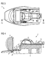
- the figure 3 is an elevation view of the module of the figure 1 .
- the figure 4 is a representation in section along the axis IV-IV of the figure 3 . It can be seen that the support 4 comprises several portions, in this case a rear portion 4 1 in contact with the plate 16 on the rear portion 6 1 of the radiator, an intermediate portion 4 2 and a front portion 4 3 disposed above the front portion 6 2 of the radiator 6 and on its bosses 6 3 .
- the lens 8 comprises two fastening tabs 8 1 extending from a lower edge to the lugs 6 4 of the radiator 6. More specifically, these lugs 8 1 extend through openings 24 in the front portion 4 3 of the support 4. These lugs 8 1 may comprise cavities, or through passages, fitting the ends of the lugs 6 4 .
- the front portion 4 3 of the support 4 is, on its underside, bearing on the bosses 3 and 6, on its upper face bears against the lens 8. The front portion 4 3 is thus vertically positioned accurately by relative to the radiator 6 as well as to the lens 8.
- the engagement between the legs 6 4 of the radiator 6 and the holes or cavities of the fastening tabs 8 1 of the lens 8 is preferably without play, more particularly with a clamping.
- the tabs 6 4 of the radiator 6 may have at their ends longitudinal ribs intended to ensure a slight tightening with the fastening tabs 8 1 of the lens.
- the material of the lens being preferably a translucent or transparent plastic material, such as for example polycarbonate, the fastening tabs 8 1 may be deformed somewhat when they are placed on the legs 6 4 , in order to avoid any play. mechanical and uncertainty as to the vertical positioning of the lens.
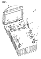
- the figure 5 illustrates the radiator 6 of the module of the figure 1 , equipped only with the lens 8 and the folder 14, the latter being represented in transparency.
- the radiator comprises ribs 6 6 in the shape of H in the longitudinal direction of the module. These ribs serve as a bearing surface for the folder 14. It is indeed important that the folder 14, more particularly its central portion 14 1 reflecting, is parallel to the upper surface of the rear portion 6 1 of the radiator 6. Indeed any misalignment of the reflective surface of the folder 14 is likely to significantly modify the photometry of the light beam of the module. It is therefore important to be able to accurately position the folder 14 not only in translation in the longitudinal direction but also vertically and in rotation about a transverse axis.
- the ribs 6 6 provide vertical and rotational positioning about a transverse axis of the folder 14. They also prevent light leakage between the underside of the central portion 14 1 and the upper face of the rear portion 6 1 of the radiator.
- the rear portion 6 1 of the radiator comprises two cavities 6 7 whose function will be detailed in relation to the Figures 8 and 9 .
- Fixing screws 20 and 22 of the plate supporting the light source and the support are visible at the figure 5 .
- the figure 6 is a cross-sectional view of the module of the figure 1 , the section being at the level of the folder 14.
- This view illustrates the mode of fixing and positioning of the folder 14. It can be observed that the central portion 14 1 of the folder is in contact with the transverse rib 6 6 of the radiator 6.
- the fastening arms 14 2 of the brake cooperate by engagement with holes in the support 4. These arms 14 2 may include for this purpose retaining tabs intended to allow the insertion of the arms 14 2 in the orifices and to prevent their exit from these orifices.
- Other fixing and / or retaining means can be envisaged.
- the ribs 6 6 illustrated in FIGS. figures 5 and 6 are preferably integral with the radiator 6.
- the latter is preferably made of metal or plastic material capable of being molded, such as for example aluminum or thermoplastics having thermal conduction properties. It is therefore interesting to make these ribs directly during the realization of the radiator.
- these ribs may deviate from that illustrated in figures 5 and 6 . Indeed, they could for example include two transverse ribs parallel and distant from each other. They could also have a U-shaped profile or in the form of a rectangle. It could also be several point bosses.
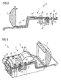
- the figure 7 is an elevation view of the module of the figure 1 . Unlike the figure 3 , the figure 7 illustrates the module provided with fixing screws 20 and 22, visible in particular at the figure 5 . As can be seen at figure 7 the cutting axis VIII-VIII passes through an oblong hole 4 5 of the support 4 as well as one of the pins 6 5 of the radiator 6. The head of the fastening screw 22 passing through this oblong hole is totally received by said hole, meaning that this screw is not supported on the support 4 but only on the plate.
- the figure 8 is a representation in section along the axis VIII-VIII of the figure 7 .
- the figure 9 is a sectional view VIII-VIII of the module of the figure 7 however, the view is in perspective and the point of view of the section opposite to that of the figure 8 .
- the support 4 comprises two lugs 4 4 , on either side of the longitudinal or optical axis of the module.
- Each of these lugs 4 4 extends from the rear portion 4 1 of the support to a cavity 6 7 , that is to say substantially vertically downwards.
- Each of the lugs 4 4 also crosses an oblong hole 16 2 formed in the plate 16 and bears in the longitudinal direction against the edge of said hole.
- the support is directed rearward, that is to say that it is the rear portion of the edge of the oblong hole 16 2 which is in contact with the lug 4 4 .
- this support could be directed forward.
- the cavities 6 7 may be sized to allow the pins 4 4 move freely when positioning the holder 4. To this end, the cavity may extend beyond the edge of 16 2 slot with which the ergot 4 4 abuts.
- the plate 16 is fixed by the screw 22 through the oblong hole 4 5 of the support.
- the plate 16 can be positioned on the radiator 6 thanks to the two pins 6 5 of said radiator which cooperate with corresponding orifices of the plate 16.
- the rear portion 4 1 of said support is deposited against the plate 16 by ensuring that the lugs 4 4 4 penetrate the oblong holes 16 2 of the plate and the cavities corresponding 6 7 of the radiator.
- 4 oblong holes 6 may be provided to cooperate with the pins on May 6 while allowing movement of the carrier 4.
- the support 4 When the rear portion 4 1 of the holder 4 is in contact with the plate 16, the support 4 can then be moved essentially in the longitudinal direction so as to bring each of the lugs 4 4 in contact with the corresponding edge of the oblong holes 16 2 of the plate.
- the fixing screws 20 bearing on the support can then be put in place and tightened in order to secure the support 4 and the plate 16 on the radiator 6.
- lugs 4 4 as stop means in the longitudinal direction acting between the support and the plate ensures exact positioning between the reflecting surface 10, supported by the support, and the light source.
- the pins and the oblong holes of the plate with which they cooperate can be designed to ensure positioning not only in the longitudinal direction but also in the transverse direction, that is to say a positioning in the plane sliding between the plate and the rear portion of the support.
- the edge of the oblong holes and / or the corresponding lug may / may be profiled (s) so as to ensure a centering of the corresponding lug.
Landscapes
- Engineering & Computer Science (AREA)
- General Engineering & Computer Science (AREA)
- Non-Portable Lighting Devices Or Systems Thereof (AREA)
- Arrangement Of Elements, Cooling, Sealing, Or The Like Of Lighting Devices (AREA)
- Physics & Mathematics (AREA)
- Microelectronics & Electronic Packaging (AREA)
- Optics & Photonics (AREA)
Abstract
Description
- L'invention a trait au domaine de l'éclairage, plus particulièrement de l'éclairage automobile. L'invention a trait à un module d'éclairage de projecteur pour véhicule automobile.
- Le document de brevet publié
EP 2 428 725 A2 divulgue un module d'éclairage de projecteur automobile. Le module d'éclairage en question comprend une source lumineuse du type diode à électroluminescence (LED) montée sur une platine disposée sur un radiateur de refroidissement de ladite diode. Le module comprend également une première surface réfléchissante en forme de demi-coquille et apte à réfléchir les rayons émis par la source lumineuse vers une deuxième surface réfléchissante, dite plieuse, avec un bord de coupure du faisceau d'éclairage. Le module d'éclairage comprend également une lentille disposée à l'avant de la deuxième surface réfléchissante. Les rayons réfléchis par la première surface réfléchissante et qui passent à l'avant du bord de coupure de la pieuse rencontrent la lentille et sont déviés par celle-ci. Les rayons rencontrant la deuxième surface réfléchissante, au lieu de rencontrer la lentille en sa partie inférieure avec un angle d'incidence plus faible que les rayons précédents, sont réfléchis vers la partie supérieure de la lentille avec un angle d'incidence essentiellement identique. Ces rayons sont alors déviés par la lentille vers le bas du faisceau au lieu d'être déviés vers le haut, réalisant ainsi une coupure typique d'un faisceau d'éclairage du type « code » ou encore feux de croisement. Dans ce module, une pièce principale sert de support à la lentille, à la surface réfléchissante en forme de demi-coquille et à la plieuse. Cette pièce est alors fixée au radiateur. Ce dernier supporte directement la platine avec la source lumineuse. Le positionnement longitudinal entre la pièce principale et le radiateur s'opère au moyen d'oeillets sur la pièce principale coopérant par engagement avec des fûts sur le radiateur. Des vis de fixation sont ensuite vissées dans les fûts afin de sécuriser la pièce principale sur le radiateur. La pièce principale comprend des surfaces de butées coopérant directement avec le radiateur en vue de son positionnement vertical. Cet enseignement est intéressant en ce que la pièce principale permet d'assurer un positionnement relatif précis entre la lentille, la surface réfléchissante, la plieuse et le radiateur. En effet, la lentille est totalement supportée par la pièce principale. Dans le cas de lentilles volumineuses et lourdes, cela peut poser quelques difficultés en termes de stabilité de la lentille notamment en présence de vibrations. De plus, la pièce principale est une pièce compliquée qui peut par ailleurs présenter certaines tolérances fabrication nuisant potentiellement à la précision de l'assemblage. - L'invention a pour objectif de pallier au moins un des inconvénients de l'art antérieur, plus particulièrement de l'art antérieur susmentionné. Plus particulièrement, l'invention a pour objectif de proposer un module d'éclairage dont la mise en oeuvre soit simplifiée tout en conservant un niveau de précision important entre la lentille et le reste du module, comme notamment la surface réfléchissante et la ou les sources lumineuses.
- L'invention a pour objet un module lumineux, notamment d'éclairage et/ou de signalisation, pour véhicule automobile, comprenant : au moins une source lumineuse ; un dissipateur thermique apte à dissiper la chaleur produite par ladite ou lesdites sources ; une surface réfléchissante apte à réfléchir les rayons de la ou des sources lumineuses ; une lentille apte à dévier les rayons provenant de la surface réfléchissante afin de former un faisceau lumineux selon un axe optique du module ; un support de la lentille et de la surface réfléchissante, ledit support étant monté sur le dissipateur thermique ; remarquable en ce que le dissipateur thermique et/ou le support comprend au moins un, préférentiellement au moins deux bossages en contact avec l'autre du dissipateur et du support de manière à maintenir une distance prédéterminée entre le dissipateur et le support.
- Selon un mode avantageux de l'invention, le ou les bossages sont dirigés verticalement.
- Selon un mode avantageux de l'invention, le ou les bossages sont situés, selon la direction de l'axe optique, entre la surface réfléchissante et la lentille.
- Selon un mode avantageux de l'invention, la lentille comprend au moins une, préférentiellement au moins deux pattes de fixation inférieures s'étendant verticalement au travers du support.
- Selon un mode avantageux de l'invention, le support comporte une encoche, la ou les pattes de fixation inférieures s'étendant à travers cette encoche.
- Selon un mode avantageux de l'invention, la ou chacune des pattes de fixation coopère par engagement avec le dissipateur thermique, ledit engagement présentant préférentiellement un jeu vertical inférieur à 0.5mm, plus préférentiellement un jeu vertical inférieur à 0.1 mm, plus préférentiellement encore un serrage vertical.
- Selon un mode avantageux de l'invention, le dissipateur thermique comprend une portion arrière supportant la ou les sources lumineuses et une portion avant, le ou les bossages étant sur la portion avant.
- Selon un mode avantageux de l'invention, la portion avant du dissipateur thermique est en contre bas de la portion arrière dudit dissipateur.
- Selon un mode avantageux de l'invention, le dissipateur thermique présente un profil en escalier, la portion avant formant une première marche dudit escalier et la portion arrière formant une deuxième marche, plus haute, dudit escalier.
- Selon un mode avantageux de l'invention, le support s'étend le long des surfaces supérieures respectives des portions avant et arrière du dissipateur thermique, la lentille étant en appui vertical sur ledit support.
- Selon un mode avantageux de l'invention, l'engagement entre la lentille et le dissipateur thermique est sur la portion avant dudit dissipateur.
- Selon un mode avantageux de l'invention, la portion avant du dissipateur thermique comprend au moins une, préférentiellement au moins deux pattes s'étendant vers l'avant et coopérant par engagement avec une ouverture dans la ou les pattes de fixation de la lentille, respectivement.
- Selon un mode avantageux de l'invention, la ou chacune des pattes du dissipateur thermique forme une butée dans la direction de l'axe optique pour la patte de fixation correspondante de la lentille.
- Selon un mode avantageux de l'invention, la ou chacune des pattes du dissipateur thermique présente un profil formant, dans la direction de l'axe optique, un ressaut.
- Selon un mode avantageux de l'invention, la ou chacune des pattes du dissipateur thermique comprend au moins une nervure s'étendant selon la direction de l'axe optique, de manière à réaliser un engagement avec serrage avec la patte de fixation correspondante de la lentille.
- Selon un mode avantageux de l'invention, au moins deux des bossages sont disposés latéralement de part et d'autre de l'axe optique du module.
- Selon un mode avantageux de l'invention, la surface réfléchissante et le support sont une même pièce. La surface réfléchissante peut être formée sur une cavité du support, par exemple par métallisation de cette cavité, le cas échéant la surface réfléchissante et le support forme une même pièce.
- Selon un mode avantageux de l'invention, le support comprend des moyens de positionnement par rapport au dissipateur thermique et selon la direction de l'axe optique.
- Selon un mode avantageux de l'invention, les moyens de positionnement du support selon la direction de l'axe optique coopèrent avec une platine supportant la ou les sources lumineuses, ladite platine étant disposée sur la portion arrière du dissipateur thermique.
- Avantageusement, la ou les sources lumineuses sont du type diode à électroluminescence.
- Avantageusement, la platine comprend un circuit imprimé, préférentiellement avec un connecteur, ledit circuit étant relié à la ou aux sources lumineuses en vue de leur alimentation.
- Selon un mode avantageux de l'invention, les moyens de positionnement du support selon la direction de l'axe optique comprennent au moins une, préférentiellement au moins deux ergots, chacun des ergots faisant saillie verticalement vers le bas dans une cavité du dissipateur thermique, ladite butée ou chacune desdites butées coopérant par contact avec le bord d'un orifice dans la platine.
- Selon un mode avantageux de l'invention, le dissipateur thermique est en matériau métallique et/ou plastique moulé, le ou au moins deux des bossages étant venus de matière avec le dissipateur et réalisés par moulage dudit dissipateur.
- L'invention a également pour objet un dispositif lumineux pour véhicule automobile, comprenant un boîtier et au moins un module lumineux, remarquable en ce que le module ou au moins un des modules est conforme à l'invention.
- Les mesures de l'invention sont intéressantes en ce qu'elles permettent de réaliser facilement et économiquement un module d'éclairage avec un positionnement précis de la lentille par rapport à la surface réfléchissante et/ou la ou les sources lumineuses.
- D'autres caractéristiques et avantages de la présente invention seront mieux compris à l'aide de la description et des dessins parmi lesquels :
- La
figure 1 est une vue en perspective d'un module d'éclairage de projecteur automobile, conforme à l'invention ; - La
figure 2 est une vue en perspective du radiateur, de la plieuse et de la source lumineuse du module de lafigure 1 ; - La
figure 3 est une vue en élévation du module de lafigure 1 , montrant un axe de coupe IV-IV ; - La
figure 4 est une vue en coupe IV-IV du module de lafigure 3 ; - La
figure 5 est une vue en perspective du radiateur pourvu de la plieuse où celle-ci est représentée en transparence, faisant apparaître des nervures de positionnement de ladite plieuse sur le radiateur ; - La
figure 6 est une vue en coupe transversale du module de lafigure 1 au niveau de la plieuse ; - La
figure 7 est une vue en élévation du module de lafigure 1 , montrant une ligne de coupe VIII-VIII ; - La
figure 8 est une vue en coupe VIII-VIII du module de lafigure 7 ; - La
figure 9 est une vue en coupe VIII-VIII du module de lafigure 7 , la vue étant toutefois en perspective et la coupe étant opposée à celle de lafigure 8 . - La
figure 1 est une représentation en perspective d'un module d'éclairage conforme à l'invention. Ce module d'éclairage peut être monté dans un projecteur de véhicule automobile. En l'occurrence, ce module produit un faisceau d'éclairage à coupure tel que pour une fonction d'éclairage du type « code » ou encore feux de croisement. - Le module d'éclairage 2 illustré à la
figure 1 comprend, essentiellement un radiateur, ou dissipateur thermique, 6 sur lequel est disposée une platine 16 pourvue d'une ou plusieurs sources lumineuses 12, préférentiellement du type diode à électroluminescence. Un support 4 représenté en transparence et s'étendant sur toute la longueur du module est disposé sur le radiateur 6. Le support est en contact avec une lentille 8 et il comprend une surface réfléchissante 10. Cette dernière présente une forme générale de demi-coquille recouvrant la source lumineuse 12. Le profil de la surface réfléchissante 10 peut être généralement elliptique avec deux foyers. La source lumineuse est située au premier foyer et une surface réfléchissante 14 est située essentiellement dans le plan de la source lumineuse et avec un bord avant située au niveau du deuxième foyer. La surface réfléchissante 14 est couramment désignée « plieuse » dans la mesure où elle réfléchit une partie des rayons provenant de la surface réfléchissante 10 vers une partie supérieure de la lentille. En effet, en l'absence de la surface réfléchissante 14, les rayons passant à l'arrière du deuxième foyer rencontreraient la lentille à une partie basse avec un angle d'incidence plus faible que ceux passant par le deuxième foyer. Ces rayons seraient alors déviés par la lentille de sorte à former la partie haute du faisceau d'éclairage. Le fait de renvoyer ces rayons vers une partie haute de la lentille permet d'inverser cet effet et de former la partie basse du faisceau. Le bord avant de la plieuse 14 forme ainsi une coupure horizontale du faisceau. On peut par ailleurs observer que la surface réfléchissante de la plieuse 14 forme un ressaut en son milieu de manière à former deux niveaux de coupure différents entre la partie gauche et la partie droite du faisceau d'éclairage, conformément à la réglementation en matière d'éclairage des véhicules en vigueur dans la plupart des pays. L'utilisation d'une plieuse en vue de former un faisceau d'éclairage à coupure est bien connu en soi de l'homme de métier. - Le faisceau d'éclairage est suivant une direction principale couramment appelée axe optique du module. Cet axe correspond également essentiellement à l'axe longitudinal du module.
- On peut également observer à la
figure 1 que la platine 16 comprend à sa partie arrière un connecteur 18 pour son branchement au faisceau électrique du projecteur et du véhicule. - La
figure 2 illustre le radiateur 6 du module de lafigure 1 , le radiateur étant équipé seulement de la plieuse 14 et de la platine 16. On peut observer que le radiateur 6 comprend une portion arrière 61 supportant la platine et une portion avant 62. La portion avant 62 est à un niveau inférieur à celui de la portion arrière 61. Le profil du radiateur 6 est similaire à celui d'un escalier, la portion avant 62 correspondant à une première marche et la portion arrière 61 formant une deuxième marche, supérieure à la première. - La plieuse 14 est située essentiellement au niveau du bord avant de la portion arrière 61. Plus précisément, la plieuse 14 comprend une portion centrale réfléchissante 141 et deux portions latérales 142 sous forme de bras de fixation au support 4 (
figure 1 ). Cette fixation sera davantage détaillée en relation avec lafigure 6 . La plieuse 14 présente ainsi un profil transversal en forme de U où seule la portion centrale 141 est active optiquement. La plieuse peut être réalisée à partir d'une portion de tôle métallique, par mise à forme, pliage et découpage. - La portion avant 62 comprend sur sa surface supérieure deux bossages 63. Ces bossages sont destinés à assurer un positionnement exact dans la direction verticale du support 4, comme cela va être détaillé en relation avec les
figures 3 et 4 . Ces bossages peuvent être plus nombreux. Il pourrait également s'agir d'un ou plusieurs bossages s'étendant transversalement, à la manière d'une nervure. - La portion avant 62 comprend également, à son bord avant, deux pattes 64 de fixation de la lentille 8 (
figure 1 ), comme cela va être détaillé en relation avec lesfigures 3 et 4 . - Comme cela est visible à la
figure 2 , la portion arrière 61 peut comprendre un ou plusieurs pions, en l'occurrence deux pions 63 destinés à traverser des orifices correspondants de la platine 16. Ces pions peuvent être généralement coniques. La platine 16 comprend également des orifices 161 destinés à recevoir des vis de fixation et des trous oblongs 162 destinés à permettre un positionnement longitudinal, c'est-à-dire suivant la direction de l'axe optique, du support 4 par rapport à la platine 16. - La
figure 3 est une vue en élévation du module de lafigure 1 . Lafigure 4 est une représentation en coupe suivant l'axe IV-IV de lafigure 3 . On peut observer que le support 4 comprend plusieurs portions, en l'occurrence une portion arrière 41 en contact avec la platine 16 sur la portion arrière 61 du radiateur, une portion intermédiaire 42 et une portion avant 43 disposée au-dessus de la portion avant 62 du radiateur 6 et sur ses bossages 63. - On peut observer à la
figure 4 que la lentille 8 comprend deux pattes de fixation 81 s'étendant depuis un bord inférieur vers les pattes 64 du radiateur 6. Plus précisément, ces pattes 81 s'étendent au travers d'ouvertures 24 dans la portion avant 43 du support 4. Ces pattes 81 peuvent comprendre des cavités, ou des passages traversant, chaussant les extrémités des pattes 64. Comme on peut l'observer à lafigure 4 , la portion avant 43 du support 4 est, sur sa face inférieure, en appui sur les bossages 63 et, sur sa face supérieure, en appui sur la lentille 8. La portion avant 43 est ainsi positionnée verticalement de manière exacte par rapport au radiateur 6 ainsi qu'à la lentille 8. - L'engagement entre les pattes 64 du radiateur 6 et les orifices ou cavités des pattes de fixation 81 de la lentille 8 est préférentiellement sans jeu, plus particulièrement avec un serrage. En référence à la
figure 2 , on peut observer que les pattes 64 du radiateur 6 peuvent présenter à leurs extrémités des nervures longitudinales destinées à assurer un léger serrage avec les pattes de fixation 81 de la lentille. Le matériau de la lentille étant préférentiellement un matériau plastique translucide ou transparent, tel que par exemple du polycarbonate, les pattes de fixation 81 peuvent se déformer quelque peu lors de leur mise en place sur les pattes 64, afin d'éviter tout jeu mécanique et incertitude quant au positionnement vertical de la lentille. - En ce qui concerne le positionnement longitudinal de la lentille 8, on peut observer à la
figure 4 , ainsi qu'à lafigure 2 , que les pattes 64 forment un profil en S, c'est-à-dire un profil avec un ressaut, ce ressaut formant une surface de butée dans la direction longitudinale du module. Le positionnement longitudinal des pattes de fixation 81 de la lentille 8 est ainsi également assuré. - Toujours à la
figure 4 , on peut observer que la plieuse, plus précisément sa portion centrale et optiquement active 141 est en appui sur une nervure 66 du radiateur, qui va être davantage détaillée en relation avec lesfigures 5 et6 . - La
figure 5 illustre le radiateur 6 du module de lafigure 1 , équipé uniquement de la lentille 8 et de la plieuse 14, cette dernière étant représentée en transparence. On peut observer que le radiateur comprend des nervures 66 en forme de H suivant la direction longitudinale du module. Ces nervures servent de surface d'appui à la plieuse 14. Il est en effet important que la plieuse 14, plus particulièrement sa portion centrale 141 réfléchissante, soit parallèle à la surface supérieure de la portion arrière 61 du radiateur 6. En effet, tout désalignement de la surface réfléchissante de la plieuse 14 est susceptible de modifier de manière sensible la photométrie du faisceau lumineux du module. Il est donc important de pouvoir positionner de manière précise la plieuse 14 non seulement en translation selon la direction longitudinale mais également verticalement et en rotation autour d'un axe transversal. Les nervures 66 assurent un positionnement vertical et en rotation autour d'un axe transversal de la plieuse 14. Elles permettent également d'éviter des fuites de lumière entre la face inférieure de la portion centrale 141 et la face supérieure de la portion arrière 61 du radiateur. - On peut également observer à la
figure 5 que la portion arrière 61 du radiateur comprend deux cavités 67 dont la fonction sera détaillée en relation avec lesfigures 8 et 9 . - Des vis de fixation 20 et 22 de la platine supportant la source lumineuse et du support sont visibles à la
figure 5 . - La
figure 6 est une vue en coupe transversale du module de lafigure 1 , la coupe étant au niveau de la plieuse 14. Cette vue illustre le mode de fixation et de positionnement de la plieuse 14. On peut observer que la portion centrale 141 de la plieuse est bien en appui sur la nervure transversale 66 du radiateur 6. On peut également observer que les bras de fixation 142 de la plieuse coopèrent par engagement avec des orifices dans le support 4. Ces bras 142 peuvent comprendre à cet effet des languettes de retenue destinées à permettre l'insertion des bras 142 dans les orifices et d'empêcher leur sortie de ces orifices. D'autres moyens de fixation et/ou de retenue peuvent être envisagés. - Les nervures 66 illustrées aux
figures 5 et6 sont préférentiellement venues de matière avec le radiateur 6. Ce dernier est préférentiellement en matériau métallique ou plastique apte à être moulé, comme par exemple de l'aluminium ou des thermoplastiques présentant des propriétés de conduction thermique. Il est donc intéressant de réaliser ces nervures directement lors de la réalisation du radiateur. - Il est à noter que la forme de ces nervures peut dévier de celle illustrée aux
figures 5 et6 . En effet, elles pourraient par exemple comprendre deux nervures transversales parallèles et distantes l'une de l'autre. Elles pourraient également présenter un profil en forme de U ou encore en forme de rectangle. Il pourrait également s'agir de plusieurs bossages ponctuels. - La
figure 7 est une vue en élévation du module de lafigure 1 . A la différence de lafigure 3 , lafigure 7 illustre le module pourvu des vis de fixation 20 et 22, visibles notamment à lafigure 5 . Comme on peut le voir à lafigure 7 , l'axe de coupe VIII-VIII passe par un trou oblong 45 du support 4 ainsi que par un des pions 65 du radiateur 6. La tête de la vis de fixation 22 traversant ce trou oblong est totalement reçue par ledit trou, signifiant que cette vis n'est pas en appui sur le support 4 mais bien uniquement sur la platine. - La
figure 8 est une représentation en coupe suivant l'axe VIII-VIII de lafigure 7 . Lafigure 9 est une vue en coupe VIII-VIII du module de lafigure 7 , la vue étant toutefois en perspective et le point de vue de la coupe étant opposé à celui de lafigure 8 . - On peut y observer que le support 4 comprend deux ergots 44, de part et d'autre de l'axe longitudinal ou optique du module. Chacun de ces ergots 44 s'étend depuis la portion arrière 41 du support vers une cavité 67, c'est-à-dire essentiellement verticalement vers le bas. Chacun des ergots 44 traverse également un trou oblong 162 pratiqué dans la platine 16 et est en appui dans la direction longitudinale contre le bord dudit trou. En l'occurrence, l'appui est dirigé vers l'arrière, c'est-à-dire que c'est la portion arrière du bord du trou oblong 162 qui est en contact avec l'ergot 44. Il est toutefois entendu qu'alternativement cet appui pourrait être dirigé vers l'avant.
- Les cavités 67 peuvent être dimensionnées pour permettre aux ergots 44 de s'y déplacer librement lors du positionnement du support 4. A cet effet, la cavité peut s'étendre au-delà du bord du trou oblong 162 avec lequel l'ergot 44 vient en butée.
- La platine 16 est fixée par la vis 22 traversant le trou oblong 45 du support. La platine 16 peut être positionnée sur le radiateur 6 grâce aux deux pions 65 dudit radiateur qui coopèrent avec des orifices correspondants de la platine 16. Lors de la mise en place du support 4, après avoir positionné et éventuellement fixé la platine 16, la portion arrière 41 dudit support est déposée contre la platine 16 en veillant à ce que les ergots 44 4 pénètrent les trous oblongs 162 de la platine et les cavités correspondantes 67 du radiateur. Des trous oblongs 46 peuvent être prévus pour coopérer avec les pions 65 tout en permettant le déplacement du support 4. Lorsque la portion arrière 41 du support 4 est en contact avec la platine 16, le support 4 peut alors être déplacé essentiellement dans la direction longitudinale de manière à amener chacun des ergots 44 en contact avec le bord correspondant des trous oblongs 162 de la platine. Les vis de fixation 20 prenant appui sur le support peuvent ensuite être mises en place et serrées afin d'assurer la fixation du support 4 ainsi que de la platine 16 sur le radiateur 6.
- L'utilisation des ergots 44 en guise de moyens de butée selon la direction longitudinale agissant entre le support et la platine permet d'assurer un positionnement exact entre la surface réfléchissante 10, supportée par le support, et la source lumineuse.
- Il est à noter que les ergots et les trous oblongs de la platine avec lesquelles ils coopèrent peuvent être conçus pour assurer un positionnement non seulement selon la direction longitudinale mais également selon la direction transversale, c'est-à-dire un positionnement dans le plan de glissement entre la platine et la portion arrière du support. A cet effet, le bord des trous oblongs et/ou l'ergot correspondant peut/peuvent être profilé(s) de manière à assurer un centrage de l'ergot correspondant.
Claims (16)
- Module lumineux (2), notamment d'éclairage et/ou de signalisation, pour véhicule automobile, comprenant :- au moins une source lumineuse (12) ;- un dissipateur thermique (6) apte à dissiper la chaleur produite par ladite ou lesdites sources lumineuses (12) ;- une surface réfléchissante (10) apte à réfléchir les rayons de la ou des sources lumineuses (12) ;- une lentille (8) apte à dévier les rayons provenant de la surface réfléchissante (10) afin de former un faisceau lumineux selon un axe optique du module ;- un support (4) de la lentille (8) et de la surface réfléchissante (10), ledit support étant monté sur le dissipateur thermique (6) ;caractérisé en ce que
le dissipateur thermique (6) et/ou le support (4) comprend au moins un, préférentiellement au moins deux bossages (63) en contact avec l'autre du dissipateur thermique (6) et du support (4) de manière à maintenir une distance prédéterminée entre le dissipateur et le support. - Module lumineux (2) selon la revendication 1, caractérisé en ce que le ou les bossages (63) sont situés, selon la direction de l'axe optique, entre la surface réfléchissante (10) et la lentille (8).
- Module lumineux (2) selon l'une des revendications 1 à 2, caractérisé en ce que la lentille (8) comprend au moins une, préférentiellement au moins deux pattes de fixation inférieures (81) s'étendant verticalement au travers du support (4).
- Module lumineux (2) selon la revendication 3, caractérisé en ce que le support comporte une encoche, la ou les pattes de fixation inférieures s'étendant à travers cette encoche.
- Module lumineux (2) selon l'une des revendications 3 et 4, caractérisé en ce que la ou chacune des pattes de fixation (81) coopère par engagement avec le dissipateur thermique (6), ledit engagement présentant préférentiellement un jeu vertical inférieur à 0.5mm, plus préférentiellement un jeu vertical inférieur à 0.1 mm, plus préférentiellement encore un serrage vertical.
- Module lumineux (2) selon l'une des revendications 1 à 5, caractérisé en ce que le dissipateur thermique (6) comprend une portion arrière (61) supportant la source lumineuse (12) et une portion avant (62), le ou les bossages (63) étant sur la portion avant (62).
- Module lumineux (2) selon la revendication 5 et la revendication 6, caractérisé en ce que l'engagement entre la lentille (8) et le dissipateur thermique (6) est sur la portion avant (62) dudit dissipateur.
- Module lumineux (2) selon la revendication 7, caractérisé en ce que la portion avant (62) du dissipateur thermique (6) comprend au moins une, préférentiellement au moins deux pattes (64) s'étendant vers l'avant et coopérant par engagement avec une ouverture dans la ou les pattes de fixation (81) de la lentille (8), respectivement.
- Module lumineux (2) selon la revendication 8, caractérisé en ce que la ou chacune des pattes du dissipateur thermique (64) forme une butée dans la direction de l'axe optique pour la patte de fixation correspondante (81) de la lentille (8).
- Module lumineux (2) selon l'une des revendications 8 et 9, caractérisé en ce que la ou chacune des pattes du dissipateur thermique (64) présente un profil, selon la direction de l'axe optique, formant un ressaut.
- Module lumineux (2) selon l'une des revendications 8 à 10, caractérisé en ce que la ou chacune des pattes du dissipateur thermique (64) comprend au moins une nervure s'étendant selon la direction de l'axe optique, de manière à réaliser un engagement avec serrage avec la patte de fixation correspondante (81) de la lentille (8).
- Module lumineux (2) selon l'une des revendications 1 à 11, caractérisé en ce que la surface réfléchissante (10) et le support (4) sont une même pièce.
- Module lumineux (2) selon l'une des revendications 1 à 12, caractérisé en ce que le support (4) comprend des moyens de positionnement (44) par rapport au dissipateur thermique (6) et selon la direction de l'axe optique.
- Module lumineux (2) selon l'une des revendications 6 à 11 et selon la revendication 13, caractérisé en ce que les moyens de positionnement (44) du support (4) selon la direction de l'axe optique coopèrent avec une platine (16) supportant la ou les sources lumineuses (12), ladite platine (16) étant disposée sur la portion arrière (61) du dissipateur thermique (6).
- Module lumineux (2) selon la revendication 14, caractérisé en ce que les moyens de positionnement du support (4) selon la direction de l'axe optique comprennent au moins une, préférentiellement au moins deux ergots (44), chacun des ergots (44) faisant saillie verticalement vers le bas dans une cavité (67) du dissipateur thermique (6), ledit ergot ou chacun desdits ergots (44) coopérant par contact avec le bord d'un orifice (162) dans la platine (16).
- Dispositif lumineux pour véhicule automobile, comprenant un boîtier et au moins un module lumineux, caractérisé en ce que le module ou au moins un des modules est conforme à l'une des revendications 1 à 15.
Applications Claiming Priority (1)
| Application Number | Priority Date | Filing Date | Title |
|---|---|---|---|
| FR1456227A FR3022974B1 (fr) | 2014-06-30 | 2014-06-30 | Module d'eclairage pour projecteur automobile avec positionnement entre reflecteur et lentille |
Publications (2)
| Publication Number | Publication Date |
|---|---|
| EP2966342A1 true EP2966342A1 (fr) | 2016-01-13 |
| EP2966342B1 EP2966342B1 (fr) | 2022-11-02 |
Family
ID=51519058
Family Applications (1)
| Application Number | Title | Priority Date | Filing Date |
|---|---|---|---|
| EP15173917.4A Active EP2966342B1 (fr) | 2014-06-30 | 2015-06-25 | Module d'éclairage de projecteur pour véhicule automobile |
Country Status (5)
| Country | Link |
|---|---|
| US (1) | US10060588B2 (fr) |
| EP (1) | EP2966342B1 (fr) |
| CN (1) | CN105222050B (fr) |
| FR (1) | FR3022974B1 (fr) |
| MX (1) | MX2015008532A (fr) |
Cited By (1)
| Publication number | Priority date | Publication date | Assignee | Title |
|---|---|---|---|---|
| EP3299702A1 (fr) * | 2016-09-26 | 2018-03-28 | Valeo Vision | Module optique lumineux de véhicule automobile |
Families Citing this family (8)
| Publication number | Priority date | Publication date | Assignee | Title |
|---|---|---|---|---|
| FR3037381B1 (fr) * | 2015-06-11 | 2021-02-19 | Valeo Vision | Dispositif de positionnement d'un support lumineux d'une diode electroluminescente sur un element support et module lumineux pour dispositif d'eclairage et/ou de signalisation comportant un tel dispositif |
| DE102017104841A1 (de) * | 2017-03-08 | 2018-09-13 | HELLA GmbH & Co. KGaA | Beleuchtungsvorrichtung für Fahrzeuge sowie Montageverfahren |
| WO2019194276A1 (fr) * | 2018-04-06 | 2019-10-10 | 株式会社小糸製作所 | Appareil d'éclairage pour véhicule, unité de modulation de lumière spatiale et unité d'appareil d'éclairage |
| JP7169189B2 (ja) * | 2018-12-27 | 2022-11-10 | 株式会社小糸製作所 | 灯具ユニット |
| JP7021999B2 (ja) * | 2018-04-06 | 2022-02-17 | 株式会社小糸製作所 | 車両用灯具 |
| WO2020151813A1 (fr) * | 2019-01-23 | 2020-07-30 | HELLA GmbH & Co. KGaA | Dispositif d'éclairage pour véhicule doté de moyens de positionnement |
| EP3757450A1 (fr) * | 2019-06-27 | 2020-12-30 | ZKW Group GmbH | Dispositif d'éclairage d'un projecteur de véhicule automobile |
| US10823356B1 (en) | 2019-12-20 | 2020-11-03 | Valeo Vision | Device and method of focusing a light |
Citations (8)
| Publication number | Priority date | Publication date | Assignee | Title |
|---|---|---|---|---|
| JP2008047383A (ja) * | 2006-08-14 | 2008-02-28 | Ichikoh Ind Ltd | 車両用灯具 |
| US20100246204A1 (en) * | 2009-03-31 | 2010-09-30 | Koito Manufacturing Co., Ltd. | Lamp unit |
| EP2428725A2 (fr) | 2010-09-10 | 2012-03-14 | Koito Manufacturing Co., Ltd. | Phare de véhicule |
| EP2522898A2 (fr) * | 2011-05-12 | 2012-11-14 | Koito Manufacturing Co., Ltd. | Lampe de véhicule |
| US20130107564A1 (en) * | 2011-07-29 | 2013-05-02 | Yasushi Yatsuda | Vehicle lighting unit |
| EP2589479A2 (fr) * | 2011-11-02 | 2013-05-08 | Zizala Lichtsysteme GmbH | Procédé de fabrication de réflecteurs |
| US20130120988A1 (en) * | 2010-07-20 | 2013-05-16 | Magna International, Inc. | Hybrid projector led low beam headlamp |
| EP2733412A2 (fr) * | 2012-11-20 | 2014-05-21 | Koito Manufacturing Co., Ltd. | Lampe véhiculaire |
Family Cites Families (8)
| Publication number | Priority date | Publication date | Assignee | Title |
|---|---|---|---|---|
| US6819506B1 (en) * | 2003-09-30 | 2004-11-16 | Infinity Trading Co. Ltd. | Optical lens system for projecting light in a lambertion pattern from a high power led light source |
| US20080165548A1 (en) * | 2006-12-27 | 2008-07-10 | Toyoda Gosei Co., Ltd. | Vehicle lighting assembly |
| JP2008204903A (ja) * | 2007-02-22 | 2008-09-04 | Ichikoh Ind Ltd | 車両用前照灯の灯具ユニット |
| JP2010080075A (ja) * | 2008-09-24 | 2010-04-08 | Ichikoh Ind Ltd | 車両用灯具 |
| US9028097B2 (en) * | 2009-10-30 | 2015-05-12 | Cree, Inc. | LED apparatus and method for accurate lens alignment |
| US8636394B2 (en) * | 2011-12-06 | 2014-01-28 | Truck-Lite Co., Llc | Light emitting diode perimeter lamp assembly |
| TWM445667U (zh) * | 2012-09-07 | 2013-01-21 | Coplus Inc | 霧燈 |
| JP6164464B2 (ja) * | 2013-04-25 | 2017-07-19 | スタンレー電気株式会社 | 車両用灯具 |
-
2014
- 2014-06-30 FR FR1456227A patent/FR3022974B1/fr not_active Expired - Fee Related
-
2015
- 2015-06-25 EP EP15173917.4A patent/EP2966342B1/fr active Active
- 2015-06-26 US US14/751,867 patent/US10060588B2/en active Active
- 2015-06-29 MX MX2015008532A patent/MX2015008532A/es unknown
- 2015-06-30 CN CN201510386332.2A patent/CN105222050B/zh active Active
Patent Citations (8)
| Publication number | Priority date | Publication date | Assignee | Title |
|---|---|---|---|---|
| JP2008047383A (ja) * | 2006-08-14 | 2008-02-28 | Ichikoh Ind Ltd | 車両用灯具 |
| US20100246204A1 (en) * | 2009-03-31 | 2010-09-30 | Koito Manufacturing Co., Ltd. | Lamp unit |
| US20130120988A1 (en) * | 2010-07-20 | 2013-05-16 | Magna International, Inc. | Hybrid projector led low beam headlamp |
| EP2428725A2 (fr) | 2010-09-10 | 2012-03-14 | Koito Manufacturing Co., Ltd. | Phare de véhicule |
| EP2522898A2 (fr) * | 2011-05-12 | 2012-11-14 | Koito Manufacturing Co., Ltd. | Lampe de véhicule |
| US20130107564A1 (en) * | 2011-07-29 | 2013-05-02 | Yasushi Yatsuda | Vehicle lighting unit |
| EP2589479A2 (fr) * | 2011-11-02 | 2013-05-08 | Zizala Lichtsysteme GmbH | Procédé de fabrication de réflecteurs |
| EP2733412A2 (fr) * | 2012-11-20 | 2014-05-21 | Koito Manufacturing Co., Ltd. | Lampe véhiculaire |
Cited By (3)
| Publication number | Priority date | Publication date | Assignee | Title |
|---|---|---|---|---|
| EP3299702A1 (fr) * | 2016-09-26 | 2018-03-28 | Valeo Vision | Module optique lumineux de véhicule automobile |
| FR3056690A1 (fr) * | 2016-09-26 | 2018-03-30 | Valeo Vision | Module optique lumineux de vehicule automobile |
| US10378723B2 (en) | 2016-09-26 | 2019-08-13 | Valeo Vision | Motor vehicle light-emitting optical module |
Also Published As
| Publication number | Publication date |
|---|---|
| US10060588B2 (en) | 2018-08-28 |
| EP2966342B1 (fr) | 2022-11-02 |
| FR3022974B1 (fr) | 2018-11-09 |
| CN105222050B (zh) | 2019-08-02 |
| MX2015008532A (es) | 2016-02-03 |
| FR3022974A1 (fr) | 2016-01-01 |
| CN105222050A (zh) | 2016-01-06 |
| US20150377439A1 (en) | 2015-12-31 |
Similar Documents
| Publication | Publication Date | Title |
|---|---|---|
| EP2966342B1 (fr) | Module d'éclairage de projecteur pour véhicule automobile | |
| EP2966343B1 (fr) | Module d'éclairage pour projecteur automobile avec positionnement entre dissipateur thermique et réflecteur/platine | |
| EP2598793B1 (fr) | Module optique de dispositif d'eclairage et/ou de signalisation d'un vehicule automobile | |
| EP2775197B1 (fr) | Dispositif d'éclairage et/ou de signalisation pour véhicule automobile, comportant un guide de lumière | |
| EP3822538B1 (fr) | Module optique de dispositif d'éclairage et/ou de signalisation d'un véhicule automobile | |
| EP4065882B1 (fr) | Module lumineux d'un véhicule automobile équipé d'un élément optique | |
| EP2921772B1 (fr) | Module lumineux d'un vehicule automobile | |
| EP2574501B1 (fr) | Dispositif d'éclairage et/ou de signalisation pour véhicule | |
| EP3489576B1 (fr) | Module lumineux pour l'éclairage et/ou la signalisation d'un véhicule automobile | |
| EP2574503A1 (fr) | Module de projecteur de véhicule avec fixation a baionnette, support et projecteur correspondant | |
| EP3537040B1 (fr) | Module lumineux et dispositif lumineux pour vehicule auto-mobile comportant un tel module lumineux | |
| EP3884206B1 (fr) | Module lumineux multifonctions doté de deux guides de lumière de type plat | |
| EP2620325B1 (fr) | Module optique | |
| EP3299702B1 (fr) | Module optique lumineux de véhicule automobile | |
| EP3486554B1 (fr) | Module lumineux pour projecteur de vehicule | |
| EP2966340B1 (fr) | Module d'éclairage de projecteur pour vehicule automobile | |
| FR2964723A1 (fr) | Module optique de dispositif d'eclairage et / ou de signalisation d'un vehicule automobile | |
| EP2966341B1 (fr) | Cache d'un module optique d'un phare de véhicule automobile | |
| FR2964724A1 (fr) | Module optique de dispositif d'eclairage et/ou de signalisation d'un vehicule automobile. | |
| FR3136833A1 (fr) | Module d’éclairage automobile avec écran bloqueur servant à positionner les sources lumineuses |
Legal Events
| Date | Code | Title | Description |
|---|---|---|---|
| PUAI | Public reference made under article 153(3) epc to a published international application that has entered the european phase |
Free format text: ORIGINAL CODE: 0009012 |
|
| AK | Designated contracting states |
Kind code of ref document: A1 Designated state(s): AL AT BE BG CH CY CZ DE DK EE ES FI FR GB GR HR HU IE IS IT LI LT LU LV MC MK MT NL NO PL PT RO RS SE SI SK SM TR |
|
| AX | Request for extension of the european patent |
Extension state: BA ME |
|
| 17P | Request for examination filed |
Effective date: 20160713 |
|
| RBV | Designated contracting states (corrected) |
Designated state(s): AL AT BE BG CH CY CZ DE DK EE ES FI FR GB GR HR HU IE IS IT LI LT LU LV MC MK MT NL NO PL PT RO RS SE SI SK SM TR |
|
| STAA | Information on the status of an ep patent application or granted ep patent |
Free format text: STATUS: EXAMINATION IS IN PROGRESS |
|
| 17Q | First examination report despatched |
Effective date: 20190614 |
|
| REG | Reference to a national code |
Ref country code: DE Ref legal event code: R079 Ref document number: 602015081394 Country of ref document: DE Free format text: PREVIOUS MAIN CLASS: F21S0008100000 Ipc: F21S0041190000 |
|
| GRAP | Despatch of communication of intention to grant a patent |
Free format text: ORIGINAL CODE: EPIDOSNIGR1 |
|
| STAA | Information on the status of an ep patent application or granted ep patent |
Free format text: STATUS: GRANT OF PATENT IS INTENDED |
|
| RIC1 | Information provided on ipc code assigned before grant |
Ipc: F21S 45/49 20180101ALI20220426BHEP Ipc: F21S 45/47 20180101ALI20220426BHEP Ipc: F21S 41/39 20180101ALI20220426BHEP Ipc: F21S 41/32 20180101ALI20220426BHEP Ipc: F21S 41/29 20180101ALI20220426BHEP Ipc: F21S 41/19 20180101AFI20220426BHEP |
|
| INTG | Intention to grant announced |
Effective date: 20220523 |
|
| GRAS | Grant fee paid |
Free format text: ORIGINAL CODE: EPIDOSNIGR3 |
|
| GRAA | (expected) grant |
Free format text: ORIGINAL CODE: 0009210 |
|
| STAA | Information on the status of an ep patent application or granted ep patent |
Free format text: STATUS: THE PATENT HAS BEEN GRANTED |
|
| AK | Designated contracting states |
Kind code of ref document: B1 Designated state(s): AL AT BE BG CH CY CZ DE DK EE ES FI FR GB GR HR HU IE IS IT LI LT LU LV MC MK MT NL NO PL PT RO RS SE SI SK SM TR |
|
| REG | Reference to a national code |
Ref country code: GB Ref legal event code: FG4D Free format text: NOT ENGLISH |
|
| REG | Reference to a national code |
Ref country code: CH Ref legal event code: EP Ref country code: AT Ref legal event code: REF Ref document number: 1528983 Country of ref document: AT Kind code of ref document: T Effective date: 20221115 |
|
| REG | Reference to a national code |
Ref country code: DE Ref legal event code: R096 Ref document number: 602015081394 Country of ref document: DE |
|
| REG | Reference to a national code |
Ref country code: IE Ref legal event code: FG4D Free format text: LANGUAGE OF EP DOCUMENT: FRENCH |
|
| REG | Reference to a national code |
Ref country code: LT Ref legal event code: MG9D |
|
| REG | Reference to a national code |
Ref country code: NL Ref legal event code: MP Effective date: 20221102 |
|
| REG | Reference to a national code |
Ref country code: AT Ref legal event code: MK05 Ref document number: 1528983 Country of ref document: AT Kind code of ref document: T Effective date: 20221102 |
|
| PG25 | Lapsed in a contracting state [announced via postgrant information from national office to epo] |
Ref country code: SE Free format text: LAPSE BECAUSE OF FAILURE TO SUBMIT A TRANSLATION OF THE DESCRIPTION OR TO PAY THE FEE WITHIN THE PRESCRIBED TIME-LIMIT Effective date: 20221102 Ref country code: PT Free format text: LAPSE BECAUSE OF FAILURE TO SUBMIT A TRANSLATION OF THE DESCRIPTION OR TO PAY THE FEE WITHIN THE PRESCRIBED TIME-LIMIT Effective date: 20230302 Ref country code: NO Free format text: LAPSE BECAUSE OF FAILURE TO SUBMIT A TRANSLATION OF THE DESCRIPTION OR TO PAY THE FEE WITHIN THE PRESCRIBED TIME-LIMIT Effective date: 20230202 Ref country code: LT Free format text: LAPSE BECAUSE OF FAILURE TO SUBMIT A TRANSLATION OF THE DESCRIPTION OR TO PAY THE FEE WITHIN THE PRESCRIBED TIME-LIMIT Effective date: 20221102 Ref country code: FI Free format text: LAPSE BECAUSE OF FAILURE TO SUBMIT A TRANSLATION OF THE DESCRIPTION OR TO PAY THE FEE WITHIN THE PRESCRIBED TIME-LIMIT Effective date: 20221102 Ref country code: ES Free format text: LAPSE BECAUSE OF FAILURE TO SUBMIT A TRANSLATION OF THE DESCRIPTION OR TO PAY THE FEE WITHIN THE PRESCRIBED TIME-LIMIT Effective date: 20221102 Ref country code: AT Free format text: LAPSE BECAUSE OF FAILURE TO SUBMIT A TRANSLATION OF THE DESCRIPTION OR TO PAY THE FEE WITHIN THE PRESCRIBED TIME-LIMIT Effective date: 20221102 |
|
| PG25 | Lapsed in a contracting state [announced via postgrant information from national office to epo] |
Ref country code: RS Free format text: LAPSE BECAUSE OF FAILURE TO SUBMIT A TRANSLATION OF THE DESCRIPTION OR TO PAY THE FEE WITHIN THE PRESCRIBED TIME-LIMIT Effective date: 20221102 Ref country code: PL Free format text: LAPSE BECAUSE OF FAILURE TO SUBMIT A TRANSLATION OF THE DESCRIPTION OR TO PAY THE FEE WITHIN THE PRESCRIBED TIME-LIMIT Effective date: 20221102 Ref country code: LV Free format text: LAPSE BECAUSE OF FAILURE TO SUBMIT A TRANSLATION OF THE DESCRIPTION OR TO PAY THE FEE WITHIN THE PRESCRIBED TIME-LIMIT Effective date: 20221102 Ref country code: IS Free format text: LAPSE BECAUSE OF FAILURE TO SUBMIT A TRANSLATION OF THE DESCRIPTION OR TO PAY THE FEE WITHIN THE PRESCRIBED TIME-LIMIT Effective date: 20230302 Ref country code: HR Free format text: LAPSE BECAUSE OF FAILURE TO SUBMIT A TRANSLATION OF THE DESCRIPTION OR TO PAY THE FEE WITHIN THE PRESCRIBED TIME-LIMIT Effective date: 20221102 Ref country code: GR Free format text: LAPSE BECAUSE OF FAILURE TO SUBMIT A TRANSLATION OF THE DESCRIPTION OR TO PAY THE FEE WITHIN THE PRESCRIBED TIME-LIMIT Effective date: 20230203 |
|
| PG25 | Lapsed in a contracting state [announced via postgrant information from national office to epo] |
Ref country code: NL Free format text: LAPSE BECAUSE OF FAILURE TO SUBMIT A TRANSLATION OF THE DESCRIPTION OR TO PAY THE FEE WITHIN THE PRESCRIBED TIME-LIMIT Effective date: 20221102 |
|
| P01 | Opt-out of the competence of the unified patent court (upc) registered |
Effective date: 20230528 |
|
| PG25 | Lapsed in a contracting state [announced via postgrant information from national office to epo] |
Ref country code: SM Free format text: LAPSE BECAUSE OF FAILURE TO SUBMIT A TRANSLATION OF THE DESCRIPTION OR TO PAY THE FEE WITHIN THE PRESCRIBED TIME-LIMIT Effective date: 20221102 Ref country code: RO Free format text: LAPSE BECAUSE OF FAILURE TO SUBMIT A TRANSLATION OF THE DESCRIPTION OR TO PAY THE FEE WITHIN THE PRESCRIBED TIME-LIMIT Effective date: 20221102 Ref country code: EE Free format text: LAPSE BECAUSE OF FAILURE TO SUBMIT A TRANSLATION OF THE DESCRIPTION OR TO PAY THE FEE WITHIN THE PRESCRIBED TIME-LIMIT Effective date: 20221102 Ref country code: DK Free format text: LAPSE BECAUSE OF FAILURE TO SUBMIT A TRANSLATION OF THE DESCRIPTION OR TO PAY THE FEE WITHIN THE PRESCRIBED TIME-LIMIT Effective date: 20221102 Ref country code: CZ Free format text: LAPSE BECAUSE OF FAILURE TO SUBMIT A TRANSLATION OF THE DESCRIPTION OR TO PAY THE FEE WITHIN THE PRESCRIBED TIME-LIMIT Effective date: 20221102 |
|
| REG | Reference to a national code |
Ref country code: DE Ref legal event code: R097 Ref document number: 602015081394 Country of ref document: DE |
|
| PG25 | Lapsed in a contracting state [announced via postgrant information from national office to epo] |
Ref country code: SK Free format text: LAPSE BECAUSE OF FAILURE TO SUBMIT A TRANSLATION OF THE DESCRIPTION OR TO PAY THE FEE WITHIN THE PRESCRIBED TIME-LIMIT Effective date: 20221102 Ref country code: AL Free format text: LAPSE BECAUSE OF FAILURE TO SUBMIT A TRANSLATION OF THE DESCRIPTION OR TO PAY THE FEE WITHIN THE PRESCRIBED TIME-LIMIT Effective date: 20221102 |
|
| PLBE | No opposition filed within time limit |
Free format text: ORIGINAL CODE: 0009261 |
|
| STAA | Information on the status of an ep patent application or granted ep patent |
Free format text: STATUS: NO OPPOSITION FILED WITHIN TIME LIMIT |
|
| 26N | No opposition filed |
Effective date: 20230803 |
|
| PG25 | Lapsed in a contracting state [announced via postgrant information from national office to epo] |
Ref country code: SI Free format text: LAPSE BECAUSE OF FAILURE TO SUBMIT A TRANSLATION OF THE DESCRIPTION OR TO PAY THE FEE WITHIN THE PRESCRIBED TIME-LIMIT Effective date: 20221102 |
|
| PG25 | Lapsed in a contracting state [announced via postgrant information from national office to epo] |
Ref country code: MC Free format text: LAPSE BECAUSE OF FAILURE TO SUBMIT A TRANSLATION OF THE DESCRIPTION OR TO PAY THE FEE WITHIN THE PRESCRIBED TIME-LIMIT Effective date: 20221102 |
|
| PG25 | Lapsed in a contracting state [announced via postgrant information from national office to epo] |
Ref country code: MC Free format text: LAPSE BECAUSE OF FAILURE TO SUBMIT A TRANSLATION OF THE DESCRIPTION OR TO PAY THE FEE WITHIN THE PRESCRIBED TIME-LIMIT Effective date: 20221102 |
|
| REG | Reference to a national code |
Ref country code: CH Ref legal event code: PL |
|
| REG | Reference to a national code |
Ref country code: BE Ref legal event code: MM Effective date: 20230630 |
|
| GBPC | Gb: european patent ceased through non-payment of renewal fee |
Effective date: 20230625 |
|
| PG25 | Lapsed in a contracting state [announced via postgrant information from national office to epo] |
Ref country code: LU Free format text: LAPSE BECAUSE OF NON-PAYMENT OF DUE FEES Effective date: 20230625 |
|
| REG | Reference to a national code |
Ref country code: IE Ref legal event code: MM4A |
|
| PG25 | Lapsed in a contracting state [announced via postgrant information from national office to epo] |
Ref country code: LU Free format text: LAPSE BECAUSE OF NON-PAYMENT OF DUE FEES Effective date: 20230625 |
|
| PG25 | Lapsed in a contracting state [announced via postgrant information from national office to epo] |
Ref country code: IE Free format text: LAPSE BECAUSE OF NON-PAYMENT OF DUE FEES Effective date: 20230625 |
|
| PG25 | Lapsed in a contracting state [announced via postgrant information from national office to epo] |
Ref country code: IE Free format text: LAPSE BECAUSE OF NON-PAYMENT OF DUE FEES Effective date: 20230625 Ref country code: GB Free format text: LAPSE BECAUSE OF NON-PAYMENT OF DUE FEES Effective date: 20230625 Ref country code: CH Free format text: LAPSE BECAUSE OF NON-PAYMENT OF DUE FEES Effective date: 20230630 |
|
| PG25 | Lapsed in a contracting state [announced via postgrant information from national office to epo] |
Ref country code: IT Free format text: LAPSE BECAUSE OF FAILURE TO SUBMIT A TRANSLATION OF THE DESCRIPTION OR TO PAY THE FEE WITHIN THE PRESCRIBED TIME-LIMIT Effective date: 20221102 Ref country code: BE Free format text: LAPSE BECAUSE OF NON-PAYMENT OF DUE FEES Effective date: 20230630 |
|
| PG25 | Lapsed in a contracting state [announced via postgrant information from national office to epo] |
Ref country code: BG Free format text: LAPSE BECAUSE OF FAILURE TO SUBMIT A TRANSLATION OF THE DESCRIPTION OR TO PAY THE FEE WITHIN THE PRESCRIBED TIME-LIMIT Effective date: 20221102 |
|
| PG25 | Lapsed in a contracting state [announced via postgrant information from national office to epo] |
Ref country code: BG Free format text: LAPSE BECAUSE OF FAILURE TO SUBMIT A TRANSLATION OF THE DESCRIPTION OR TO PAY THE FEE WITHIN THE PRESCRIBED TIME-LIMIT Effective date: 20221102 |
|
| PGFP | Annual fee paid to national office [announced via postgrant information from national office to epo] |
Ref country code: DE Payment date: 20250617 Year of fee payment: 11 |
|
| PGFP | Annual fee paid to national office [announced via postgrant information from national office to epo] |
Ref country code: FR Payment date: 20250630 Year of fee payment: 11 |
|
| PG25 | Lapsed in a contracting state [announced via postgrant information from national office to epo] |
Ref country code: CY Free format text: LAPSE BECAUSE OF FAILURE TO SUBMIT A TRANSLATION OF THE DESCRIPTION OR TO PAY THE FEE WITHIN THE PRESCRIBED TIME-LIMIT; INVALID AB INITIO Effective date: 20150625 |
|
| PG25 | Lapsed in a contracting state [announced via postgrant information from national office to epo] |
Ref country code: HU Free format text: LAPSE BECAUSE OF FAILURE TO SUBMIT A TRANSLATION OF THE DESCRIPTION OR TO PAY THE FEE WITHIN THE PRESCRIBED TIME-LIMIT; INVALID AB INITIO Effective date: 20150625 |
|
| PG25 | Lapsed in a contracting state [announced via postgrant information from national office to epo] |
Ref country code: TR Free format text: LAPSE BECAUSE OF FAILURE TO SUBMIT A TRANSLATION OF THE DESCRIPTION OR TO PAY THE FEE WITHIN THE PRESCRIBED TIME-LIMIT Effective date: 20221102 |