EP2966599A1 - Vorrichtung zum identifizieren eines elements aus beton - Google Patents
Vorrichtung zum identifizieren eines elements aus beton Download PDFInfo
- Publication number
- EP2966599A1 EP2966599A1 EP15306077.7A EP15306077A EP2966599A1 EP 2966599 A1 EP2966599 A1 EP 2966599A1 EP 15306077 A EP15306077 A EP 15306077A EP 2966599 A1 EP2966599 A1 EP 2966599A1
- Authority
- EP
- European Patent Office
- Prior art keywords
- identification
- concrete element
- radio
- housing
- concrete
- Prior art date
- Legal status (The legal status is an assumption and is not a legal conclusion. Google has not performed a legal analysis and makes no representation as to the accuracy of the status listed.)
- Granted
Links
Images


Classifications
-
- G—PHYSICS
- G06—COMPUTING OR CALCULATING; COUNTING
- G06K—GRAPHICAL DATA READING; PRESENTATION OF DATA; RECORD CARRIERS; HANDLING RECORD CARRIERS
- G06K19/00—Record carriers for use with machines and with at least a part designed to carry digital markings
- G06K19/06—Record carriers for use with machines and with at least a part designed to carry digital markings characterised by the kind of the digital marking, e.g. shape, nature, code
- G06K19/067—Record carriers with conductive marks, printed circuits or semiconductor circuit elements, e.g. credit or identity cards also with resonating or responding marks without active components
- G06K19/07—Record carriers with conductive marks, printed circuits or semiconductor circuit elements, e.g. credit or identity cards also with resonating or responding marks without active components with integrated circuit chips
- G06K19/077—Constructional details, e.g. mounting of circuits in the carrier
- G06K19/0772—Physical layout of the record carrier
- G06K19/07728—Physical layout of the record carrier the record carrier comprising means for protection against impact or bending, e.g. protective shells or stress-absorbing layers around the integrated circuit
-
- B—PERFORMING OPERATIONS; TRANSPORTING
- B28—WORKING CEMENT, CLAY, OR STONE
- B28B—SHAPING CLAY OR OTHER CERAMIC COMPOSITIONS; SHAPING SLAG; SHAPING MIXTURES CONTAINING CEMENTITIOUS MATERIAL, e.g. PLASTER
- B28B23/00—Arrangements specially adapted for the production of shaped articles with elements wholly or partly embedded in the moulding material; Production of reinforced objects
- B28B23/0031—Arrangements specially adapted for the production of shaped articles with elements wholly or partly embedded in the moulding material; Production of reinforced objects with product identification means, e.g. labels on test products or integrated circuit tags inside products RFID
-
- G—PHYSICS
- G06—COMPUTING OR CALCULATING; COUNTING
- G06K—GRAPHICAL DATA READING; PRESENTATION OF DATA; RECORD CARRIERS; HANDLING RECORD CARRIERS
- G06K19/00—Record carriers for use with machines and with at least a part designed to carry digital markings
- G06K19/06—Record carriers for use with machines and with at least a part designed to carry digital markings characterised by the kind of the digital marking, e.g. shape, nature, code
- G06K19/067—Record carriers with conductive marks, printed circuits or semiconductor circuit elements, e.g. credit or identity cards also with resonating or responding marks without active components
- G06K19/07—Record carriers with conductive marks, printed circuits or semiconductor circuit elements, e.g. credit or identity cards also with resonating or responding marks without active components with integrated circuit chips
- G06K19/077—Constructional details, e.g. mounting of circuits in the carrier
- G06K19/07749—Constructional details, e.g. mounting of circuits in the carrier the record carrier being capable of non-contact communication, e.g. constructional details of the antenna of a non-contact smart card
- G06K19/07758—Constructional details, e.g. mounting of circuits in the carrier the record carrier being capable of non-contact communication, e.g. constructional details of the antenna of a non-contact smart card arrangements for adhering the record carrier to further objects or living beings, functioning as an identification tag
Definitions
- the present invention relates to the field of civil engineering. It concerns more precisely the devices for the identification of concrete elements for the purposes in particular of their traceability / monitoring.
- Such concrete elements may consist for example of voussoirs for the support of arches of tunnels or subway.
- the document WO-2009/038661 proposes a solution for the traceability of such concrete elements, based on so-called radio-identification technology.
- the proposed solution uses an identification device comprising a housing intended to be partially embedded in the concrete and in which are reported radio-identification means provided with a radio-communicating chip.
- the seal between the casing walls is provided by a weld type assembly, for example an ultrasonic weld or a heat seal.
- Such a structure allows, in a simple and fast manner, an optimum seal which avoids in particular infiltration of the milt concrete between the inner faces of the housing and the support plate of the radio-identification means.
- This advantage is particularly important when it is envisaged to be able to visualize information written on the wafer.
- the present invention also relates to the concrete element equipped with an identification device according to the invention, wherein the housing is partially embedded in said concrete element, with its front wall flush with the surface of said concrete element.
- This concrete element consists for example of a voussoir for a tunnel.
- the identification device 1 is intended to allow the identification of a concrete element, this at least by radio-identification technology (or "RFID” for "Radio Frequency Identification”).
- This identification of concrete elements is particularly useful for the purposes of traceability and monitoring of the latter.
- concrete elements in particular prefabricated concrete elements, possibly in reinforced concrete.
- Such concrete element consist for example of a reinforced concrete voussoir for the support of the vault of a tunnel (for example for the metro).
- the identification device 1 comprises radio identification means 2 which are sealed in a housing 3 intended to be embedded (or taken) partially in the concrete element to be identified.
- the radio identification means 2 integrate the radio-identification function.
- radio-identification is meant in particular a technique which makes it possible to identify and track objects by means of a radio-identifier.
- a technique which makes it possible to identify objects by using a memory chip or an electronic device capable of storing information and, with the aid of a radio antenna, to transmit this information to a specialized reader.
- radio identification means 2 are also found under the name “tag” or "label” or “transponder”.
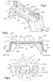
- the radio identification means 2 represented in isolation on the figure 6 , thus comprise a support 21 carrying a radio-communicating chip 22.
- the support 21 here consists of a support plate which is made of an elastomeric material.
- elastomeric material in particular a material having a high elasticity and which, even if it is drawn strongly and repeatedly, returns to its original length as soon as the tension ceases.
- this elastomeric material is selected from the soft silicone, interesting for its qualities of resistance to impact, vibration, bending and baking temperature.
- the upper faces 211 and lower 212 are here flat, and they are arranged parallel to one another.
- optically visible signs 23 of the upper face 211 consist for example of optical identification signs which consist of a number 231 and a barcode 232.
- the peripheral edge 213 comprises in turn two longitudinal edges 2131 and two transverse edges 2132.
- the support 21 is also provided with two through orifices 214, intended to cooperate with complementary pads of the housing 3 ( figure 3 ), to optimize the positioning of said support 21 during its assembly.
- Each through orifice 214 is formed near one of the two transverse edges 2132 of the support 21.
- the radio-communicating chip 22, conventional in itself, is trapped in the support 21 to protect it against particular mechanical shocks and fluids.
- Such a radio-communicating chip 22 advantageously consists of an electronic chip (or integrated circuit) associated with an antenna.
- This radio-communicating chip 22 is for example passive, that is to say that the electronic chip retromodulates the wave from a reader to transmit information.
- the passive "tag” generally uses the wave (magnetic or electromagnetic) from the reader to power the on-board electronic circuit.
- the HF-type chips have the advantage of being detectable at a limited distance, generally of the order of a few centimeters, which makes it possible to identify them individually.
- UHF chips have the particular advantage of being detectable at a greater distance, usually several meters, which allows to identify them in groups.
- This radio-communicating chip 22 advantageously contains a unique identifier, chosen for example from "UII” for “Unique Item Identifier” or "Code EPC” for "Electronic Product Code”, which is returned in response to a radio request sent from a reader transmitter receiver.
- a unique identifier chosen for example from "UII” for "Unique Item Identifier” or "Code EPC” for "Electronic Product Code”
- This unique identifier is advantageously non-modifiable, and typically consists of a numeric or alphanumeric code.
- This unique identifier is preferably identical to that represented by (encoded in) the identification optical signs 23 affixed to the upper face 211 of the support 21. This redundancy is useful for securing the identifier by different technologies.
- Such a unique identifier can be registered in a database, to allow its pairing with other data useful for tracking the concrete element intended to carry the identification device 1.
- the housing 3 is structured to encapsulate / wrap these radio identification means 2 while ensuring their anchoring in the concrete element.
- the housing 3 has two walls 31, 32 which extend opposite and at a distance from one another to sandwich the radio identification means 2.
- the front wall 31 is advantageously transparent, to visually access the optical identification signs 23 affixed to the upper face 211 of the support 21 of the radio identification means 2.
- peripheral edges 313, 323 of the walls 31, 32 are identical, or almost identical, with respect to each other.
- peripheral edges 313, 323 each comprise two longitudinal edges 3131, 3231 and two transverse edges 3132, 3232.
- the inner faces 311, 321 of the walls 31, 32 of the housing 3 thus clamp the support 21 of the radiating identification means 2 between them.
- Sealing means are provided between the inner faces 311, 321 of the housing 3 and the support 21 of the radio identification means 2, to form a compression seal which is able to prevent the passage of fluid (In particular concrete) between said inner faces 311, 321 and the support 21 reported.
- the sealing means are here formed by two peripheral ribs 314, 324 which are formed, respectively, on the inner faces 311, 321 facing the walls 31, 32 of the housing 3.
- peripheral ribs 314, 324 have a generally rectangular shape.
- the height H separating the inner faces 311, 321 of the walls 31, 32 of the housing 3 is advantageously identical, with the clearance, to the thickness R of the support 21 (that is to say the distance separating its two faces 211, 212) ( figure 3 ).
- the height H is chosen so as to obtain optimal compression of the support 21, without, however, damaging it.
- peripheral ribs 314, 324 protruding from the inner faces 311, 321 of the walls 31, 32, are thus sinking into the support 21 because of its elasticity.
- the front wall 31 is here monobloc with anchoring means 33 in the concrete element.
- the anchoring means 33 here consist of a rear base which extends on the side of the rear face 311 of the front wall 31 (or, where appropriate, on the side of the rear wall 32) and which is connected to its peripheral edge 313.
- anchoring means 33 are here divergent (that is to say a rear base 33 whose section increases with the distance relative to the front wall 31), for their stacking as described below in connection with the figure 7 .
- the anchoring means 33 comprise a skirt 331, connected to the peripheral edge 313 of the front wall 31, which is extended by two end tabs 332 each terminated by a lug 333.
- the two end tabs 332 are formed in the extension of the transverse edges 3132 of the front wall 31 and deviate from each other, from the front wall 31.
- the lugs 333 extend in the same plane, and parallel to the general plane of the front wall 31.
- Each of the lugs 333 has a through opening 3331 defining a longitudinal longitudinal axis 3331 '.
- the longitudinal longitudinal axes 3331 'of the lugs 333 extend parallel to each other. relative to the other and perpendicular to the general plane of the front wall 31 ( figure 2 ).
- the inner face 311 of the front wall 31 is further provided with two one-piece lateral studs 315 which are each intended to fit through one of the through orifices 214 of the support 21 of the radio-identification means 2.
- These one-piece lateral pads 315 serve to position the support 21, before the application of the rear wall 32.
- the outer face 312 of the same front wall 31 is further equipped with degradable fixing means 316, used for assembling this identification device 1 with a mold for manufacturing the concrete element (as described below in FIG. relationship with the figure 8 ).
- degradable fastening means 316 here consist of two stud structures each provided to be introduced by elastic engagement (or clipping) in a complementary receiving orifice formed in the mold.
- the front walls 31 and rear 32 are here assembled by means of securing means by elastic interlocking.
- the peripheral edge 323 of the rear wall 32 is provided with a set of lugs 328 (forming a tenon) distributed along its longitudinal edges 3231 ( figure 5 ).
- the skirt 331 of the front wall 31 is provided with complementary housings 318 (forming a mortise) which are formed along the two longitudinal edges 3131 of the peripheral edge 313 of the front wall 31 ( figure 4 ).
- the housing 3 comprises a keying pin, useful for properly orienting the housing 3 in the mold by a constant visual orientation.
- the identification device 1 is obtained, firstly, by removing the radio identification means 2 against the front wall 31 of the housing 3.
- the support 21 is attached so that its front face 211 is oriented facing the inner face 311 of the front wall 31 of the housing 3.
- This removal is accompanied by an insertion of the lateral studs 315 of the front wall 31 through the through orifices 214 of the support 21 ( figure 3 ).
- the rear wall 32 of the housing 3 is then attached to the front wall 31, against the support 21, to activate the elastic interlocking means 318, 328.
- This rear wall 32 is for that reported so that its inner face 321 comes opposite the lower face 212 of the support 21 of the radio identification means 2.
- the radio identification means 2 are thus sealedly wrapped between the two walls 31, 32 of the housing 3.
- the sealing is here ensured by the peripheral ribs 314, 324 of the inner faces 311, 321 facing the walls 31, 32 of the housing 3, which each engage in the faces 211, 212 of the support 21 means radio identification 2.
- peripheral ribs 314, 324 delimit a perimeter surrounding the radiocommunication chip 22 and the optically visible signs 23 of the upper face 211 of the support 21.
- peripheral ribs 314, 324 of the inner faces 311, 321 thus form two seals by compression, with the faces 211, 212 of the support 21 of the radio identification means 2, which are able to prevent the passage of fluids.
- the identification devices 1 thus obtained can be stored in a column ( figure 7 ), this in particular thanks to the flared shape of their anchoring means 33.
- each identification device 1 is oriented so that its anchoring means 33 covers the upper wall 31 and the anchoring means 33 of the identification device 1 directly underlying.
- Holding rods 8 may be reported in aligned through apertures 3331, allowing ergonomic storage and transportation.
- the identification device 1 is first deposited in a mold 9 which has an inner surface 91 for defining the surface of the concrete element E.
- the inner surface 91 of the mold 9 is intended to define the surface of a concrete element E of the type voussoir.
- this mold 9 is provided with ad-hoc perforations 92 for the assembly by elastic interlocking of the degradable fixing means 316 fitted to the front wall 31 of the identification device 1 (FIG. figure 8 ).
- the outer face 312 of the front wall 31 is thus pressed against the inner surface 91 of the mold 9, to limit the passage of concrete between them during the subsequent casting step.
- reinforcement steel are suitably reported in the mold 9.
- the concrete then flows around the anchoring means 33 of the identification device 1, and comes to marry its rear wall 32, to ensure their grip in the solidified concrete.
- the sealing means 314, 324 of the identification device 1 prevent milk from the concrete from infiltrating between the walls 31, 32 of the housing 3 and the radio identification means 2.
- This phenomenon of infiltration would lead in particular to affect the visibility of the optical identification signs 23 carried by the support 21 of the radio-identification means 2.
- the housing 3 is also sufficiently robust in the case of steaming at high temperature (above 70 ° C) with wet steam.
- the concrete element E carrying the identification device 1 is demolded from the mold 9 ( figure 9 ).
- the degradable fixing means 316 can be cut and discarded.
- the front wall 31 of the identification device 1 (and in particular its outer face 312) is thus flush with respect to the surface E1 of the concrete element E ( figure 9 ).
- the radio identification means 2 are effectively secured to the concrete element E since they are trapped between, on the one hand, the front wall 31 whose anchoring means 33 are embedded in the concrete and, on the other hand, the rear wall 32 covered by the concrete.
- the concrete element E can thus be monitored throughout its life by means of its identification device 1 partially embedded in its material, which protects it in addition to external aggressions.
- the radio identification means 2 and the optical identification signs 23 can then be read without difficulty through the front wall 31 of the housing 3, for the follow-up of this prefabricated concrete element E.
- This identification device 1 can be read by means of different technologies, in this case a radio-identification technology and / or an optical technology (for example barcode and / or direct visual).
- This reading can be performed for example by means of a fixed reader or by means of a manual trigger connected to a network.
Landscapes
- Engineering & Computer Science (AREA)
- Microelectronics & Electronic Packaging (AREA)
- Computer Hardware Design (AREA)
- Physics & Mathematics (AREA)
- General Physics & Mathematics (AREA)
- Theoretical Computer Science (AREA)
- Manufacturing & Machinery (AREA)
- Chemical & Material Sciences (AREA)
- Ceramic Engineering (AREA)
- Mechanical Engineering (AREA)
- Manufacturing Of Tubular Articles Or Embedded Moulded Articles (AREA)
- On-Site Construction Work That Accompanies The Preparation And Application Of Concrete (AREA)
Applications Claiming Priority (1)
| Application Number | Priority Date | Filing Date | Title |
|---|---|---|---|
| FR1456752A FR3023639B1 (fr) | 2014-07-11 | 2014-07-11 | Dispositif pour l'identification d'un element en beton |
Publications (3)
| Publication Number | Publication Date |
|---|---|
| EP2966599A1 true EP2966599A1 (de) | 2016-01-13 |
| EP2966599B1 EP2966599B1 (de) | 2016-12-21 |
| EP2966599B8 EP2966599B8 (de) | 2017-04-12 |
Family
ID=51726705
Family Applications (1)
| Application Number | Title | Priority Date | Filing Date |
|---|---|---|---|
| EP15306077.7A Not-in-force EP2966599B8 (de) | 2014-07-11 | 2015-07-02 | Vorrichtung zum identifizieren eines elements aus beton |
Country Status (4)
| Country | Link |
|---|---|
| EP (1) | EP2966599B8 (de) |
| DK (1) | DK2966599T3 (de) |
| ES (1) | ES2620490T3 (de) |
| FR (1) | FR3023639B1 (de) |
Cited By (2)
| Publication number | Priority date | Publication date | Assignee | Title |
|---|---|---|---|---|
| US20160167851A1 (en) * | 2010-07-14 | 2016-06-16 | Hubbell Incorporated | Utility Cover Identification System |
| CN107392299A (zh) * | 2017-08-23 | 2017-11-24 | 北京好运达智创科技有限公司 | 一种轨道交通混凝土预制件电子标签装置及其使用方法 |
Families Citing this family (1)
| Publication number | Priority date | Publication date | Assignee | Title |
|---|---|---|---|---|
| CN108766204B (zh) * | 2018-05-23 | 2020-12-01 | 广东正迪科技股份有限公司 | 防伪标识及方法 |
Citations (2)
| Publication number | Priority date | Publication date | Assignee | Title |
|---|---|---|---|---|
| WO2004000679A1 (en) * | 2002-06-24 | 2003-12-31 | Buildnow Pte Ltd. | Tamper-evident information storage device protector |
| WO2009038661A1 (en) | 2007-09-14 | 2009-03-26 | International Coding Technologies | Radio frequency identification system and method for use in cast concrete components |
-
2014
- 2014-07-11 FR FR1456752A patent/FR3023639B1/fr active Active
-
2015
- 2015-07-02 DK DK15306077.7T patent/DK2966599T3/en active
- 2015-07-02 EP EP15306077.7A patent/EP2966599B8/de not_active Not-in-force
- 2015-07-02 ES ES15306077.7T patent/ES2620490T3/es active Active
Patent Citations (2)
| Publication number | Priority date | Publication date | Assignee | Title |
|---|---|---|---|---|
| WO2004000679A1 (en) * | 2002-06-24 | 2003-12-31 | Buildnow Pte Ltd. | Tamper-evident information storage device protector |
| WO2009038661A1 (en) | 2007-09-14 | 2009-03-26 | International Coding Technologies | Radio frequency identification system and method for use in cast concrete components |
Cited By (3)
| Publication number | Priority date | Publication date | Assignee | Title |
|---|---|---|---|---|
| US20160167851A1 (en) * | 2010-07-14 | 2016-06-16 | Hubbell Incorporated | Utility Cover Identification System |
| US10647483B2 (en) * | 2010-07-14 | 2020-05-12 | Hubbell Incorporated | Utility cover identification system |
| CN107392299A (zh) * | 2017-08-23 | 2017-11-24 | 北京好运达智创科技有限公司 | 一种轨道交通混凝土预制件电子标签装置及其使用方法 |
Also Published As
| Publication number | Publication date |
|---|---|
| DK2966599T3 (en) | 2017-04-03 |
| FR3023639B1 (fr) | 2016-07-08 |
| EP2966599B8 (de) | 2017-04-12 |
| EP2966599B1 (de) | 2016-12-21 |
| ES2620490T3 (es) | 2017-06-28 |
| FR3023639A1 (fr) | 2016-01-15 |
Similar Documents
| Publication | Publication Date | Title |
|---|---|---|
| EP2966599B1 (de) | Vorrichtung zum identifizieren eines elements aus beton | |
| US20100096455A1 (en) | Edge mounted rfid tag | |
| EP0669597A1 (de) | Verfahren zur Herstellung einer kontaktlosen Karte | |
| EP3233539B1 (de) | Haltevorrichtung zum montieren eines elektronischen bauteils auf einem reifen | |
| EP2207130B1 (de) | Kennschild für Holz mit Rückverfolgbarkeit durch RFID-UHF-Technik | |
| US20160300131A1 (en) | Radio frequency identification tag in a license plate | |
| US9592955B2 (en) | Container and container joint structure | |
| EP3684681A1 (de) | Ausrichtung zur herstellung einer schwimmenden photovoltaischen anlage | |
| FR2963141A1 (fr) | Etiquette electronique sans contact | |
| KR101598148B1 (ko) | 수직 옹벽 축조용 블록 유닛 | |
| EP0922555B1 (de) | Formverfahren zur Herstellung eines Kunststoffgegenstandes versehen auf einer Oberfläche mit einem Einsatz geringer Dicke und so hergestellter Gegenstand | |
| FR3135645A1 (fr) | Objet ou structure multi-matériaux transformable à base de matériaux actifs et procédé d’impression 4D par assemblage volumique | |
| JP2016053874A (ja) | Rfidタグ及び管理システム並びにrfidタグの製造方法 | |
| JP2003016408A (ja) | 強化非接触データキャリア及びその製造方法 | |
| EP3005246A1 (de) | Modulares funkidentifikationssystem mit einem passiven rfid-modul und einem aktiven rfid-modul | |
| FR2821463A1 (fr) | Dispositif d'authentification de plaques mineralogiques | |
| WO2013057076A1 (fr) | Module d'encodage sans contact de carte plastique | |
| EP4409463B1 (de) | Verfahren zur überprüfung und verfolgung eines bauprodukts | |
| EP2625652B1 (de) | Sicheres elektronisches modul, vorrichtung mit einem sicheren elektronischen modul und herstellungsverfahren | |
| KR102237851B1 (ko) | 연약지반용 앵커링 플러그를 구비한 지하매설물 표시못 및 이를 이용한 지하매설물 관리시스템 | |
| JP6302774B2 (ja) | 筐体 | |
| FR2907894A1 (fr) | "borne topographique" | |
| EP2256713A1 (de) | Signierelement zum Kennzeichnen von Holzpaletten | |
| US20070120291A1 (en) | Method for forming lugs of micro-SD | |
| FR3010979A1 (fr) | Dispositif tel une bouteille en plastique permettant un empilement |
Legal Events
| Date | Code | Title | Description |
|---|---|---|---|
| PUAI | Public reference made under article 153(3) epc to a published international application that has entered the european phase |
Free format text: ORIGINAL CODE: 0009012 |
|
| AK | Designated contracting states |
Kind code of ref document: A1 Designated state(s): AL AT BE BG CH CY CZ DE DK EE ES FI FR GB GR HR HU IE IS IT LI LT LU LV MC MK MT NL NO PL PT RO RS SE SI SK SM TR |
|
| AX | Request for extension of the european patent |
Extension state: BA ME |
|
| 17P | Request for examination filed |
Effective date: 20160302 |
|
| RBV | Designated contracting states (corrected) |
Designated state(s): AL AT BE BG CH CY CZ DE DK EE ES FI FR GB GR HR HU IE IS IT LI LT LU LV MC MK MT NL NO PL PT RO RS SE SI SK SM TR |
|
| GRAP | Despatch of communication of intention to grant a patent |
Free format text: ORIGINAL CODE: EPIDOSNIGR1 |
|
| INTG | Intention to grant announced |
Effective date: 20160708 |
|
| GRAS | Grant fee paid |
Free format text: ORIGINAL CODE: EPIDOSNIGR3 |
|
| STAA | Information on the status of an ep patent application or granted ep patent |
Free format text: STATUS: GRANT OF PATENT IS INTENDED |
|
| GRAA | (expected) grant |
Free format text: ORIGINAL CODE: 0009210 |
|
| STAA | Information on the status of an ep patent application or granted ep patent |
Free format text: STATUS: THE PATENT HAS BEEN GRANTED |
|
| AK | Designated contracting states |
Kind code of ref document: B1 Designated state(s): AL AT BE BG CH CY CZ DE DK EE ES FI FR GB GR HR HU IE IS IT LI LT LU LV MC MK MT NL NO PL PT RO RS SE SI SK SM TR |
|
| REG | Reference to a national code |
Ref country code: GB Ref legal event code: FG4D Free format text: NOT ENGLISH |
|
| REG | Reference to a national code |
Ref country code: CH Ref legal event code: EP |
|
| REG | Reference to a national code |
Ref country code: IE Ref legal event code: FG4D Free format text: LANGUAGE OF EP DOCUMENT: FRENCH |
|
| REG | Reference to a national code |
Ref country code: AT Ref legal event code: REF Ref document number: 856073 Country of ref document: AT Kind code of ref document: T Effective date: 20170115 |
|
| REG | Reference to a national code |
Ref country code: DE Ref legal event code: R096 Ref document number: 602015001058 Country of ref document: DE |
|
| PG25 | Lapsed in a contracting state [announced via postgrant information from national office to epo] |
Ref country code: LV Free format text: LAPSE BECAUSE OF FAILURE TO SUBMIT A TRANSLATION OF THE DESCRIPTION OR TO PAY THE FEE WITHIN THE PRESCRIBED TIME-LIMIT Effective date: 20161221 |
|
| RAP2 | Party data changed (patent owner data changed or rights of a patent transferred) |
Owner name: BONNA SABLA |
|
| REG | Reference to a national code |
Ref country code: DK Ref legal event code: T3 Effective date: 20170327 |
|
| REG | Reference to a national code |
Ref country code: SE Ref legal event code: TRGR |
|
| REG | Reference to a national code |
Ref country code: NL Ref legal event code: FP |
|
| REG | Reference to a national code |
Ref country code: LT Ref legal event code: MG4D |
|
| PG25 | Lapsed in a contracting state [announced via postgrant information from national office to epo] |
Ref country code: GR Free format text: LAPSE BECAUSE OF FAILURE TO SUBMIT A TRANSLATION OF THE DESCRIPTION OR TO PAY THE FEE WITHIN THE PRESCRIBED TIME-LIMIT Effective date: 20170322 Ref country code: LT Free format text: LAPSE BECAUSE OF FAILURE TO SUBMIT A TRANSLATION OF THE DESCRIPTION OR TO PAY THE FEE WITHIN THE PRESCRIBED TIME-LIMIT Effective date: 20161221 |
|
| REG | Reference to a national code |
Ref country code: FR Ref legal event code: PLFP Year of fee payment: 3 |
|
| REG | Reference to a national code |
Ref country code: AT Ref legal event code: MK05 Ref document number: 856073 Country of ref document: AT Kind code of ref document: T Effective date: 20161221 Ref country code: NO Ref legal event code: T2 Effective date: 20161221 |
|
| PG25 | Lapsed in a contracting state [announced via postgrant information from national office to epo] |
Ref country code: RS Free format text: LAPSE BECAUSE OF FAILURE TO SUBMIT A TRANSLATION OF THE DESCRIPTION OR TO PAY THE FEE WITHIN THE PRESCRIBED TIME-LIMIT Effective date: 20161221 Ref country code: HR Free format text: LAPSE BECAUSE OF FAILURE TO SUBMIT A TRANSLATION OF THE DESCRIPTION OR TO PAY THE FEE WITHIN THE PRESCRIBED TIME-LIMIT Effective date: 20161221 |
|
| REG | Reference to a national code |
Ref country code: ES Ref legal event code: FG2A Ref document number: 2620490 Country of ref document: ES Kind code of ref document: T3 Effective date: 20170628 |
|
| PG25 | Lapsed in a contracting state [announced via postgrant information from national office to epo] |
Ref country code: IS Free format text: LAPSE BECAUSE OF FAILURE TO SUBMIT A TRANSLATION OF THE DESCRIPTION OR TO PAY THE FEE WITHIN THE PRESCRIBED TIME-LIMIT Effective date: 20170421 Ref country code: EE Free format text: LAPSE BECAUSE OF FAILURE TO SUBMIT A TRANSLATION OF THE DESCRIPTION OR TO PAY THE FEE WITHIN THE PRESCRIBED TIME-LIMIT Effective date: 20161221 Ref country code: SK Free format text: LAPSE BECAUSE OF FAILURE TO SUBMIT A TRANSLATION OF THE DESCRIPTION OR TO PAY THE FEE WITHIN THE PRESCRIBED TIME-LIMIT Effective date: 20161221 Ref country code: CZ Free format text: LAPSE BECAUSE OF FAILURE TO SUBMIT A TRANSLATION OF THE DESCRIPTION OR TO PAY THE FEE WITHIN THE PRESCRIBED TIME-LIMIT Effective date: 20161221 Ref country code: RO Free format text: LAPSE BECAUSE OF FAILURE TO SUBMIT A TRANSLATION OF THE DESCRIPTION OR TO PAY THE FEE WITHIN THE PRESCRIBED TIME-LIMIT Effective date: 20161221 |
|
| PG25 | Lapsed in a contracting state [announced via postgrant information from national office to epo] |
Ref country code: PL Free format text: LAPSE BECAUSE OF FAILURE TO SUBMIT A TRANSLATION OF THE DESCRIPTION OR TO PAY THE FEE WITHIN THE PRESCRIBED TIME-LIMIT Effective date: 20161221 Ref country code: BG Free format text: LAPSE BECAUSE OF FAILURE TO SUBMIT A TRANSLATION OF THE DESCRIPTION OR TO PAY THE FEE WITHIN THE PRESCRIBED TIME-LIMIT Effective date: 20170321 Ref country code: SM Free format text: LAPSE BECAUSE OF FAILURE TO SUBMIT A TRANSLATION OF THE DESCRIPTION OR TO PAY THE FEE WITHIN THE PRESCRIBED TIME-LIMIT Effective date: 20161221 Ref country code: AT Free format text: LAPSE BECAUSE OF FAILURE TO SUBMIT A TRANSLATION OF THE DESCRIPTION OR TO PAY THE FEE WITHIN THE PRESCRIBED TIME-LIMIT Effective date: 20161221 Ref country code: PT Free format text: LAPSE BECAUSE OF FAILURE TO SUBMIT A TRANSLATION OF THE DESCRIPTION OR TO PAY THE FEE WITHIN THE PRESCRIBED TIME-LIMIT Effective date: 20170421 |
|
| REG | Reference to a national code |
Ref country code: DE Ref legal event code: R097 Ref document number: 602015001058 Country of ref document: DE |
|
| PLBE | No opposition filed within time limit |
Free format text: ORIGINAL CODE: 0009261 |
|
| STAA | Information on the status of an ep patent application or granted ep patent |
Free format text: STATUS: NO OPPOSITION FILED WITHIN TIME LIMIT |
|
| 26N | No opposition filed |
Effective date: 20170922 |
|
| PG25 | Lapsed in a contracting state [announced via postgrant information from national office to epo] |
Ref country code: SI Free format text: LAPSE BECAUSE OF FAILURE TO SUBMIT A TRANSLATION OF THE DESCRIPTION OR TO PAY THE FEE WITHIN THE PRESCRIBED TIME-LIMIT Effective date: 20161221 |
|
| REG | Reference to a national code |
Ref country code: IE Ref legal event code: MM4A |
|
| PG25 | Lapsed in a contracting state [announced via postgrant information from national office to epo] |
Ref country code: IE Free format text: LAPSE BECAUSE OF NON-PAYMENT OF DUE FEES Effective date: 20170702 |
|
| REG | Reference to a national code |
Ref country code: FR Ref legal event code: PLFP Year of fee payment: 4 |
|
| PG25 | Lapsed in a contracting state [announced via postgrant information from national office to epo] |
Ref country code: LU Free format text: LAPSE BECAUSE OF NON-PAYMENT OF DUE FEES Effective date: 20170702 |
|
| PG25 | Lapsed in a contracting state [announced via postgrant information from national office to epo] |
Ref country code: MT Free format text: LAPSE BECAUSE OF FAILURE TO SUBMIT A TRANSLATION OF THE DESCRIPTION OR TO PAY THE FEE WITHIN THE PRESCRIBED TIME-LIMIT Effective date: 20161221 |
|
| REG | Reference to a national code |
Ref country code: CH Ref legal event code: PL |
|
| PG25 | Lapsed in a contracting state [announced via postgrant information from national office to epo] |
Ref country code: LI Free format text: LAPSE BECAUSE OF NON-PAYMENT OF DUE FEES Effective date: 20180731 Ref country code: CH Free format text: LAPSE BECAUSE OF NON-PAYMENT OF DUE FEES Effective date: 20180731 |
|
| PG25 | Lapsed in a contracting state [announced via postgrant information from national office to epo] |
Ref country code: MC Free format text: LAPSE BECAUSE OF FAILURE TO SUBMIT A TRANSLATION OF THE DESCRIPTION OR TO PAY THE FEE WITHIN THE PRESCRIBED TIME-LIMIT Effective date: 20161221 Ref country code: HU Free format text: LAPSE BECAUSE OF FAILURE TO SUBMIT A TRANSLATION OF THE DESCRIPTION OR TO PAY THE FEE WITHIN THE PRESCRIBED TIME-LIMIT; INVALID AB INITIO Effective date: 20150702 |
|
| PGFP | Annual fee paid to national office [announced via postgrant information from national office to epo] |
Ref country code: FI Payment date: 20190606 Year of fee payment: 5 Ref country code: DK Payment date: 20190611 Year of fee payment: 5 Ref country code: IT Payment date: 20190611 Year of fee payment: 5 |
|
| PGFP | Annual fee paid to national office [announced via postgrant information from national office to epo] |
Ref country code: BE Payment date: 20190604 Year of fee payment: 5 Ref country code: SE Payment date: 20190604 Year of fee payment: 5 Ref country code: FR Payment date: 20190604 Year of fee payment: 5 Ref country code: NL Payment date: 20190719 Year of fee payment: 5 |
|
| PG25 | Lapsed in a contracting state [announced via postgrant information from national office to epo] |
Ref country code: CY Free format text: LAPSE BECAUSE OF FAILURE TO SUBMIT A TRANSLATION OF THE DESCRIPTION OR TO PAY THE FEE WITHIN THE PRESCRIBED TIME-LIMIT Effective date: 20161221 |
|
| PGFP | Annual fee paid to national office [announced via postgrant information from national office to epo] |
Ref country code: ES Payment date: 20190807 Year of fee payment: 5 Ref country code: NO Payment date: 20190723 Year of fee payment: 5 Ref country code: GB Payment date: 20190604 Year of fee payment: 5 Ref country code: DE Payment date: 20190606 Year of fee payment: 5 |
|
| PG25 | Lapsed in a contracting state [announced via postgrant information from national office to epo] |
Ref country code: MK Free format text: LAPSE BECAUSE OF FAILURE TO SUBMIT A TRANSLATION OF THE DESCRIPTION OR TO PAY THE FEE WITHIN THE PRESCRIBED TIME-LIMIT Effective date: 20161221 |
|
| PG25 | Lapsed in a contracting state [announced via postgrant information from national office to epo] |
Ref country code: TR Free format text: LAPSE BECAUSE OF FAILURE TO SUBMIT A TRANSLATION OF THE DESCRIPTION OR TO PAY THE FEE WITHIN THE PRESCRIBED TIME-LIMIT Effective date: 20161221 |
|
| PG25 | Lapsed in a contracting state [announced via postgrant information from national office to epo] |
Ref country code: AL Free format text: LAPSE BECAUSE OF FAILURE TO SUBMIT A TRANSLATION OF THE DESCRIPTION OR TO PAY THE FEE WITHIN THE PRESCRIBED TIME-LIMIT Effective date: 20161221 |
|
| REG | Reference to a national code |
Ref country code: DE Ref legal event code: R119 Ref document number: 602015001058 Country of ref document: DE |
|
| REG | Reference to a national code |
Ref country code: FI Ref legal event code: MAE |
|
| REG | Reference to a national code |
Ref country code: DK Ref legal event code: EBP Effective date: 20200731 Ref country code: NO Ref legal event code: MMEP |
|
| REG | Reference to a national code |
Ref country code: SE Ref legal event code: EUG |
|
| REG | Reference to a national code |
Ref country code: NL Ref legal event code: MM Effective date: 20200801 |
|
| GBPC | Gb: european patent ceased through non-payment of renewal fee |
Effective date: 20200702 |
|
| REG | Reference to a national code |
Ref country code: BE Ref legal event code: MM Effective date: 20200731 |
|
| PG25 | Lapsed in a contracting state [announced via postgrant information from national office to epo] |
Ref country code: GB Free format text: LAPSE BECAUSE OF NON-PAYMENT OF DUE FEES Effective date: 20200702 Ref country code: NL Free format text: LAPSE BECAUSE OF NON-PAYMENT OF DUE FEES Effective date: 20200801 Ref country code: NO Free format text: LAPSE BECAUSE OF NON-PAYMENT OF DUE FEES Effective date: 20200731 Ref country code: FR Free format text: LAPSE BECAUSE OF NON-PAYMENT OF DUE FEES Effective date: 20200731 Ref country code: FI Free format text: LAPSE BECAUSE OF NON-PAYMENT OF DUE FEES Effective date: 20200702 |
|
| PG25 | Lapsed in a contracting state [announced via postgrant information from national office to epo] |
Ref country code: BE Free format text: LAPSE BECAUSE OF NON-PAYMENT OF DUE FEES Effective date: 20200731 Ref country code: DE Free format text: LAPSE BECAUSE OF NON-PAYMENT OF DUE FEES Effective date: 20210202 Ref country code: SE Free format text: LAPSE BECAUSE OF NON-PAYMENT OF DUE FEES Effective date: 20200703 |
|
| PG25 | Lapsed in a contracting state [announced via postgrant information from national office to epo] |
Ref country code: DK Free format text: LAPSE BECAUSE OF NON-PAYMENT OF DUE FEES Effective date: 20200731 |
|
| PG25 | Lapsed in a contracting state [announced via postgrant information from national office to epo] |
Ref country code: IT Free format text: LAPSE BECAUSE OF NON-PAYMENT OF DUE FEES Effective date: 20200702 |
|
| REG | Reference to a national code |
Ref country code: ES Ref legal event code: FD2A Effective date: 20211129 |
|
| PG25 | Lapsed in a contracting state [announced via postgrant information from national office to epo] |
Ref country code: ES Free format text: LAPSE BECAUSE OF NON-PAYMENT OF DUE FEES Effective date: 20200703 |