EP2966880A1 - Ensemble haut-parleur - Google Patents
Ensemble haut-parleur Download PDFInfo
- Publication number
- EP2966880A1 EP2966880A1 EP15173499.3A EP15173499A EP2966880A1 EP 2966880 A1 EP2966880 A1 EP 2966880A1 EP 15173499 A EP15173499 A EP 15173499A EP 2966880 A1 EP2966880 A1 EP 2966880A1
- Authority
- EP
- European Patent Office
- Prior art keywords
- shellpot
- speaker
- basket
- speaker basket
- insert member
- Prior art date
- Legal status (The legal status is an assumption and is not a legal conclusion. Google has not performed a legal analysis and makes no representation as to the accuracy of the status listed.)
- Granted
Links
Images



Classifications
-
- H—ELECTRICITY
- H04—ELECTRIC COMMUNICATION TECHNIQUE
- H04R—LOUDSPEAKERS, MICROPHONES, GRAMOPHONE PICK-UPS OR LIKE ACOUSTIC ELECTROMECHANICAL TRANSDUCERS; ELECTRIC HEARING AIDS; PUBLIC ADDRESS SYSTEMS
- H04R9/00—Transducers of moving-coil, moving-strip, or moving-wire type
- H04R9/02—Details
- H04R9/04—Construction, mounting, or centering of coil
- H04R9/045—Mounting
-
- H—ELECTRICITY
- H04—ELECTRIC COMMUNICATION TECHNIQUE
- H04R—LOUDSPEAKERS, MICROPHONES, GRAMOPHONE PICK-UPS OR LIKE ACOUSTIC ELECTROMECHANICAL TRANSDUCERS; ELECTRIC HEARING AIDS; PUBLIC ADDRESS SYSTEMS
- H04R31/00—Apparatus or processes specially adapted for the manufacture of transducers or diaphragms therefor
-
- H—ELECTRICITY
- H04—ELECTRIC COMMUNICATION TECHNIQUE
- H04R—LOUDSPEAKERS, MICROPHONES, GRAMOPHONE PICK-UPS OR LIKE ACOUSTIC ELECTROMECHANICAL TRANSDUCERS; ELECTRIC HEARING AIDS; PUBLIC ADDRESS SYSTEMS
- H04R9/00—Transducers of moving-coil, moving-strip, or moving-wire type
- H04R9/02—Details
- H04R9/025—Magnetic circuit
-
- H—ELECTRICITY
- H04—ELECTRIC COMMUNICATION TECHNIQUE
- H04R—LOUDSPEAKERS, MICROPHONES, GRAMOPHONE PICK-UPS OR LIKE ACOUSTIC ELECTROMECHANICAL TRANSDUCERS; ELECTRIC HEARING AIDS; PUBLIC ADDRESS SYSTEMS
- H04R9/00—Transducers of moving-coil, moving-strip, or moving-wire type
- H04R9/06—Loudspeakers
-
- H—ELECTRICITY
- H04—ELECTRIC COMMUNICATION TECHNIQUE
- H04R—LOUDSPEAKERS, MICROPHONES, GRAMOPHONE PICK-UPS OR LIKE ACOUSTIC ELECTROMECHANICAL TRANSDUCERS; ELECTRIC HEARING AIDS; PUBLIC ADDRESS SYSTEMS
- H04R2209/00—Details of transducers of the moving-coil, moving-strip, or moving-wire type covered by H04R9/00 but not provided for in any of its subgroups
- H04R2209/024—Manufacturing aspects of the magnetic circuit of loudspeaker or microphone transducers
-
- H—ELECTRICITY
- H04—ELECTRIC COMMUNICATION TECHNIQUE
- H04R—LOUDSPEAKERS, MICROPHONES, GRAMOPHONE PICK-UPS OR LIKE ACOUSTIC ELECTROMECHANICAL TRANSDUCERS; ELECTRIC HEARING AIDS; PUBLIC ADDRESS SYSTEMS
- H04R2231/00—Details of apparatus or processes specially adapted for the manufacture of transducers or diaphragms therefor covered by H04R31/00, not provided for in its subgroups
- H04R2231/003—Manufacturing aspects of the outer suspension of loudspeaker or microphone diaphragms or of their connecting aspects to said diaphragms
-
- H—ELECTRICITY
- H04—ELECTRIC COMMUNICATION TECHNIQUE
- H04R—LOUDSPEAKERS, MICROPHONES, GRAMOPHONE PICK-UPS OR LIKE ACOUSTIC ELECTROMECHANICAL TRANSDUCERS; ELECTRIC HEARING AIDS; PUBLIC ADDRESS SYSTEMS
- H04R2400/00—Loudspeakers
- H04R2400/11—Aspects regarding the frame of loudspeaker transducers
-
- H—ELECTRICITY
- H04—ELECTRIC COMMUNICATION TECHNIQUE
- H04R—LOUDSPEAKERS, MICROPHONES, GRAMOPHONE PICK-UPS OR LIKE ACOUSTIC ELECTROMECHANICAL TRANSDUCERS; ELECTRIC HEARING AIDS; PUBLIC ADDRESS SYSTEMS
- H04R31/00—Apparatus or processes specially adapted for the manufacture of transducers or diaphragms therefor
- H04R31/006—Interconnection of transducer parts
Definitions
- Embodiments relate to a speaker assembly including a shellpot coupled with a speaker basket and a method of assembling the speaker assembly.
- Plastic speaker baskets may be used to reduce weight and provide a low cost structure for certain speaker applications.
- plastic speaker baskets are molded directly over a metallic speaker shellpot, and then the rest of the speaker components are assembled in relation to the shellpot.
- the shellpot geometry often changes based on the design of the speaker assembly. Accordingly, new tooling, such as a new mold or mold detail, must be produced for each shellpot design, as well as each set of production tooling. As such, supporting multiple speaker designs can significantly increase manufacturing cost and complexity.
- Some previous designs have accomplished attaching the shellpot to the plastic basket using either a twist lock design and/or using an adhesive to bond the shellpot to the plastic speaker basket. Although such designs allow the attachment of any of multiple shellpots to a common plastic basket, these designs may have insufficient durability for some applications. Further, a twisting or locking detail may lead to increased tooling complexity and manufacturing issues.
- Loudspeakers convert electrical energy into sound and typically include a diaphragm, one or more magnets, a core cap, and a voice coil connected to the diaphragm and positioned in an air gap between the magnets and shellpot.
- the core cap can direct and concentrate a magnetic flux produced by the magnets into the air gap.
- an induced magnetic field can be created that interacts with the magnetic flux in the air gap.
- the interaction between the voice coil current and the magnetic flux causes linear oscillation of the voice coil within the air gap, which moves the diaphragm in order to produce audible sound.
- the magnet structure of some loudspeakers may result in fringe magnetic fields that can increase the risk of reducing the efficiency of the loudspeaker. Magnetic flux density should be maintained across the length of the air gap for sufficient linear voice coil travel and optimal speaker performance.
- a speaker assembly including a shellpot for receiving a speaker motor, the shellpot including an upstanding rim on an upper portion of the shellpot, and speaker basket including a base portion having an opening therein for receiving the shellpot.
- An insert member is disposed adjacent the speaker basket and the rim, wherein a plurality of sections of the rim are displaced to abut the insert member and couple the shellpot to the speaker basket.
- a speaker assembly including a shellpot for receiving a speaker motor, the shellpot including a an upstanding rim on an upper portion of the shellpot, and a speaker basket including a base portion having an opening therein for receiving the shellpot.
- a metallic insert ring is disposed adjacent the speaker basket and the rim, the insert ring having an inner portion which abuts the rim to couple the shellpot to the speaker basket and a generally concave outer portion extending into the speaker basket.
- a method of assembling a speaker assembly including providing a shellpot including an upstanding rim on an upper portion of the shellpot and providing a speaker basket including a base portion having an opening therein. The method further includes placing the speaker basket over the shellpot such that the shellpot is received in the opening and placing an insert member over the shellpot adjacent the speaker basket and the rim. A plurality of sections of the rim are displaced to abut the insert member and couple the shellpot to the speaker basket.
- a speaker assembly 10 may include a shellpot 12, a speaker basket 14 for receiving and supporting the shellpot 12, and at least one speaker motor 16 received in the shellpot 12.
- the speaker basket 14 may be formed of a plastic material, for example, a polycarbonate material or any other thermoplastic resin-based material.
- the shellpot 12 may be constructed from a metallic material or other rigid material.
- the speaker motor 16 may comprise an assembly including a back plate or center pole, a permanent magnet, and a front or top plate (components not shown).
- the diameter of the speaker motor 16 is less than that of the shellpot 12, thus a space is formed between the motor 16 and the shellpot 12 which is known as the magnetic air gap 18.
- the motor assembly provides a substantially uniform magnetic field in the air gap 18.
- a voice coil 20 is positioned within the air gap 18 and extends upwardly to join a diaphragm (not shown).
- current from an amplifier (not shown) or some other device supplying electrical signals representing program material to be transduced by the loudspeaker may drive the voice coil 20.
- Axial reciprocation of the voice coil 20 in the air gap 18 in connection with the diaphragm generates sound representing the program material transduced by the loudspeaker.
- Other speaker components may alternatively or additionally be included in the speaker assembly 10.
- the speaker basket 14 includes a base portion 22 having an opening 24 therein for receiving the shellpot 12.
- the speaker basket 14 may further include a lip 26 surrounding the opening 24, and may include a flange 28 spaced outwardly from and extending downwardly from the opening 24. It is understood that directional terms such as, but not limited to, "upwardly” and “downwardly” as used herein are to provide reference with respect to the drawings and are not otherwise intended to be limiting.
- the shellpot 12 may include an upper portion 30 and a lower portion 32.
- the upper portion 30 and the lower portion 32 have generally equal diameters, although the shellpot 12 is not limited to this configuration.
- the shellpot 12 includes a protrusion 34 formed along an outer surface 36 thereof and extending circumferentially around the shellpot 12, demarcating the upper portion 30 from the lower portion 32.
- the protrusion 34 has a generally rectangular cross-section, although other configurations are also contemplated.
- the shellpot 12 includes an upstanding rim 37 on the upper portion 30 of the shellpot 12, spaced from the protrusion 34. While the rim 37 is shown as extending upwardly in a generally perpendicular orientation to a plane of the protrusion 34, it is understood that the rim 37 is not limited to this configuration.
- An insert member 40 may be disposed adjacent the speaker basket 14 and the rim 37, such as between the lip 26 of the speaker basket 14 and the rim 37, in order to couple the shellpot 12 to the speaker basket 14.
- the insert member 40 comprises a generally planar ring having a diameter sized to surround the rim 37 or upper portion 30 of the shellpot 12, as shown in Figs. 1-4 .
- the insert member 40 may have any thickness suitable for the purpose of coupling the shellpot 12 and the speaker basket 14, and may be constructed from a metallic material, although other materials, such as plastic, may alternatively be used.
- the shellpot 12 is received into the opening 24, such as from an exterior of the speaker basket 14.
- the insert member 40 is placed over the shellpot 12, such as from an interior of the speaker basket 14.
- the insert member 40 may be positioned adjacent the rim 37 and the lip 26 of the speaker basket 14.
- a plurality of sections 38 of the rim 37 may be displaced or swedged, such as manually or by a machine, to abut the insert member 40 and couple the shellpot 12 and the speaker basket 14.
- the sections 38 are in a spaced configuration circumferentially around the rim 37, although the position of the sections 38 is not limited to this configuration. While eight sections 38 are illustrated in Fig. 4 , other numbers of sections 38 are also contemplated.
- the sections 38 may also be of any width sufficient to capture the insert member 40 between the shellpot 12 and the speaker basket 14.
- the basket lip 26 may be disposed on an upper surface 42 of the shellpot protrusion 34.
- the basket flange 28 may engage an end surface 44 of the protrusion 34 when the shellpot 12 is coupled with the speaker basket 14. The engagement of each of the lip 26 and the flange 28 with the protrusion 34 may serve to further stabilize and strengthen the coupling of the shellpot 12 and speaker basket 14.
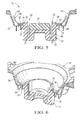
- an insert member 50 may be provided comprising an annular member or ring having an inner portion 52 and an outer portion 54.
- the inner portion 52 which may be generally planar, is abutted by the sections 38 to couple the shellpot 12 to the speaker basket 14 in the manner described above with reference to Figs. 1-4 .
- the outer portion 54 extends upwardly into the speaker basket 14.
- the outer portion 54 may be generally concave, such that the insert member 50 has a dish-shaped configuration. It is understood that the outer portion 54 may alternatively have another geometry besides the concave configuration depicted herein.
- a metallic insert member 50 with its outer portion 54 extending into the speaker basket 14 may also help reduce stray magnetic fields by collecting the magnetic flux, thus maintaining magnetic flux density across the length of the air gap 18 to allow for sufficient movement of the voice coil 20 to result in optimum speaker performance.
- an insert member 40, 50 allows the shellpot 12 to be assembled to the speaker basket 14 without the use of insert molding.
- the speaker basket 14 may be placed over the shellpot 12 and then the insert member 40, 50 placed over the shellpot 12, adjacent the upstanding rim 37, wherein a plurality of sections 38 of the rim 37 are then displaced or swedged so that the sections 38 abut the insert member 40, 50 to couple the shellpot 12 and the speaker basket 14.
- no additional adhesive or other fasteners are required to secure the shellpot 12 and the speaker basket 14 together.
- the shellpot 12 and speaker basket 14 can be fastened together easily and securely, and the assembly operation can proceed without needing to allot any time required for adhesive material to harden or additional fasteners to be installed.
- This attachment interface also allows for the use of multiple shellpot 12 configurations and, thus speaker motor 16 designs, with a single speaker basket 14, thereby reducing manufacturing complexity and cost of the speaker assembly 10.
Landscapes
- Engineering & Computer Science (AREA)
- Physics & Mathematics (AREA)
- Acoustics & Sound (AREA)
- Signal Processing (AREA)
- Manufacturing & Machinery (AREA)
- Audible-Bandwidth Dynamoelectric Transducers Other Than Pickups (AREA)
- Details Of Audible-Bandwidth Transducers (AREA)
Applications Claiming Priority (1)
| Application Number | Priority Date | Filing Date | Title |
|---|---|---|---|
| US14/325,927 US9723410B2 (en) | 2014-07-08 | 2014-07-08 | Speaker assembly |
Publications (2)
| Publication Number | Publication Date |
|---|---|
| EP2966880A1 true EP2966880A1 (fr) | 2016-01-13 |
| EP2966880B1 EP2966880B1 (fr) | 2020-03-11 |
Family
ID=53483737
Family Applications (1)
| Application Number | Title | Priority Date | Filing Date |
|---|---|---|---|
| EP15173499.3A Active EP2966880B1 (fr) | 2014-07-08 | 2015-06-24 | Ensemble haut-parleur |
Country Status (3)
| Country | Link |
|---|---|
| US (1) | US9723410B2 (fr) |
| EP (1) | EP2966880B1 (fr) |
| CN (1) | CN105282633B (fr) |
Families Citing this family (2)
| Publication number | Priority date | Publication date | Assignee | Title |
|---|---|---|---|---|
| KR102519045B1 (ko) | 2016-07-28 | 2023-04-07 | 삼성전자주식회사 | 냉장고 |
| US10869128B2 (en) | 2018-08-07 | 2020-12-15 | Pangissimo Llc | Modular speaker system |
Citations (4)
| Publication number | Priority date | Publication date | Assignee | Title |
|---|---|---|---|---|
| GB1013161A (en) * | 1962-01-29 | 1965-12-15 | Aldo Ludivico Coen | Transducer construction |
| US3614335A (en) * | 1968-08-08 | 1971-10-19 | Int Standard Electric Corp | Electroacoustic transducer held together by thermoplastic clamping ring |
| US20020044671A1 (en) * | 2000-06-26 | 2002-04-18 | Katsuya Shimomura | Loudspeaker |
| US20070230738A1 (en) * | 2006-03-28 | 2007-10-04 | Eric Royse | Speaker assembly with mounting plate |
Family Cites Families (25)
| Publication number | Priority date | Publication date | Assignee | Title |
|---|---|---|---|---|
| US2894182A (en) * | 1955-10-19 | 1959-07-07 | Gen Electric | Electro-acoustic transducer |
| US3133162A (en) | 1961-09-06 | 1964-05-12 | Aldo L Coen | Loud speaker structure |
| US3240882A (en) * | 1962-01-31 | 1966-03-15 | Gen Electric | Permanent magnet type loudspeakers |
| DE1219521B (de) * | 1964-01-08 | 1966-06-23 | Standard Elektrik Lorenz Ag | Elektrodynamischer Wandler der Fernmeldetechnik |
| US3176086A (en) * | 1964-03-27 | 1965-03-30 | Aldo L Coen | Transducer field structure assembly |
| JPS5853299A (ja) | 1981-09-25 | 1983-03-29 | Seiko Instr & Electronics Ltd | 動電形スピ−カ |
| US4565905A (en) * | 1982-04-28 | 1986-01-21 | International Jensen Incoporated | Loudspeaker construction |
| US4752963A (en) | 1985-06-12 | 1988-06-21 | Kabushiki Kaisha Kenwood | Electroacoustic converter having a recessed step on the center pole |
| DE3541493A1 (de) | 1985-11-23 | 1987-06-04 | Philips Patentverwaltung | Vorrichtung zum einbau eines lautsprechers in einen ausschnitt einer schallwand |
| US4852178A (en) | 1987-10-02 | 1989-07-25 | Motorola, Inc. | Speaker retaining assembly |
| DE4031742A1 (de) * | 1990-10-06 | 1992-04-09 | Nokia Unterhaltungselektronik | Kalotten-hochton-lautsprecher |
| US5416283A (en) | 1994-02-17 | 1995-05-16 | Adac Plastics, Inc. | Drop-in speaker mount |
| GB9712964D0 (en) | 1997-06-19 | 1997-08-27 | Goodmans Loudspeakers Limited | Loudspeakers |
| WO1999041941A1 (fr) | 1998-02-17 | 1999-08-19 | Koninklijke Philips Electronics N.V. | Transducteur electroacoustique et diaphragme destine a un transducteur |
| DE69911861T2 (de) | 1998-02-17 | 2004-07-29 | Koninklijke Philips Electronics N.V. | Elektroakustischer wandler und membran für elektroakustischen wandler |
| DE69941562D1 (de) * | 1998-07-21 | 2009-12-03 | Harman Int Ind | Miniaturisierter breitbandlautsprecher |
| JP3416815B2 (ja) | 2000-02-17 | 2003-06-16 | ミネベア株式会社 | スピーカおよびその製造方法 |
| JP3971625B2 (ja) * | 2002-02-25 | 2007-09-05 | フォスター電機株式会社 | 薄型スピーカおよびその製造方法 |
| US7031490B2 (en) * | 2002-03-26 | 2006-04-18 | T C Sounds Inc. | Speaker driver with detachable motor and basket |
| JP4499580B2 (ja) * | 2005-02-17 | 2010-07-07 | パイオニア株式会社 | スピーカー装置用のフレーム及びスピーカー装置 |
| US7873178B2 (en) | 2005-04-19 | 2011-01-18 | Harman International Industries, Incorporation | Electro-dynamic planar loudspeaker |
| JP4592500B2 (ja) | 2005-06-02 | 2010-12-01 | パイオニア株式会社 | スピーカー装置及びその製造方法 |
| JP2007208592A (ja) * | 2006-02-01 | 2007-08-16 | Sanyo Electric Co Ltd | スピーカユニット |
| US8270660B2 (en) * | 2006-07-03 | 2012-09-18 | Pioneer Corporation | Speaker device and speaker unit |
| US8374379B2 (en) | 2007-08-30 | 2013-02-12 | Jl Audio, Inc. | Loudspeaker with replaceable motor assembly |
-
2014
- 2014-07-08 US US14/325,927 patent/US9723410B2/en active Active
-
2015
- 2015-06-17 CN CN201510336988.3A patent/CN105282633B/zh active Active
- 2015-06-24 EP EP15173499.3A patent/EP2966880B1/fr active Active
Patent Citations (4)
| Publication number | Priority date | Publication date | Assignee | Title |
|---|---|---|---|---|
| GB1013161A (en) * | 1962-01-29 | 1965-12-15 | Aldo Ludivico Coen | Transducer construction |
| US3614335A (en) * | 1968-08-08 | 1971-10-19 | Int Standard Electric Corp | Electroacoustic transducer held together by thermoplastic clamping ring |
| US20020044671A1 (en) * | 2000-06-26 | 2002-04-18 | Katsuya Shimomura | Loudspeaker |
| US20070230738A1 (en) * | 2006-03-28 | 2007-10-04 | Eric Royse | Speaker assembly with mounting plate |
Also Published As
| Publication number | Publication date |
|---|---|
| US20160014523A1 (en) | 2016-01-14 |
| EP2966880B1 (fr) | 2020-03-11 |
| CN105282633A (zh) | 2016-01-27 |
| US9723410B2 (en) | 2017-08-01 |
| CN105282633B (zh) | 2019-12-17 |
Similar Documents
| Publication | Publication Date | Title |
|---|---|---|
| KR101078960B1 (ko) | 라우드스피커 자속 집속 시스템 | |
| US8520885B2 (en) | Composite speaker | |
| CN102387451B (zh) | 拼合磁体扬声器 | |
| JPH02260799A (ja) | スピーカおよびその製造方法 | |
| EP2941017B1 (fr) | Ensemble haut-parleur | |
| US9723410B2 (en) | Speaker assembly | |
| KR101538635B1 (ko) | 방수 마이크로스피커 | |
| CN109951771B (zh) | 具有封闭膜的扬声器以及相关组装方法 | |
| US7995785B2 (en) | Speaker assembly with mounting plate | |
| JP6238302B2 (ja) | 骨伝導デバイス | |
| WO2013140719A1 (fr) | Circuit magnétique pour haut-parleur, et haut-parleur utilisant celui-ci | |
| KR101216273B1 (ko) | 진동자 | |
| US20250119690A1 (en) | Improved loudspeaker and method of manufacture | |
| EP4344244B1 (fr) | Ensemble haut-parleur avec aimant couplé mécaniquement | |
| US20110051986A1 (en) | Magnetic System for an Electroacoustic Transducer | |
| JP6295764B2 (ja) | 骨伝導デバイス | |
| CN209964295U (zh) | 扬声器 | |
| JP3985187B2 (ja) | スピーカの磁気回路構造及びスピーカ | |
| KR101439911B1 (ko) | 링플레이트를 부착한 진동판 및 이를 구비하는 마이크로스피커 | |
| JP5340187B2 (ja) | スピーカ | |
| JP5724767B2 (ja) | スピーカ用外磁型磁気回路ユニット及びその製造方法 | |
| CN118474635A (zh) | 电声转换装置及其制造方法 | |
| JP7291888B2 (ja) | スピーカ装置の製造方法、およびスピーカ装置 | |
| JP2007318346A (ja) | スピーカ装置の製造方法、スピーカ装置、およびスピーカ装置の組立治具 | |
| JP5781951B2 (ja) | 薄型スピーカ |
Legal Events
| Date | Code | Title | Description |
|---|---|---|---|
| PUAI | Public reference made under article 153(3) epc to a published international application that has entered the european phase |
Free format text: ORIGINAL CODE: 0009012 |
|
| AK | Designated contracting states |
Kind code of ref document: A1 Designated state(s): AL AT BE BG CH CY CZ DE DK EE ES FI FR GB GR HR HU IE IS IT LI LT LU LV MC MK MT NL NO PL PT RO RS SE SI SK SM TR |
|
| AX | Request for extension of the european patent |
Extension state: BA ME |
|
| 17P | Request for examination filed |
Effective date: 20160713 |
|
| RBV | Designated contracting states (corrected) |
Designated state(s): AL AT BE BG CH CY CZ DE DK EE ES FI FR GB GR HR HU IE IS IT LI LT LU LV MC MK MT NL NO PL PT RO RS SE SI SK SM TR |
|
| STAA | Information on the status of an ep patent application or granted ep patent |
Free format text: STATUS: REQUEST FOR EXAMINATION WAS MADE |
|
| R17P | Request for examination filed (corrected) |
Effective date: 20160713 |
|
| STAA | Information on the status of an ep patent application or granted ep patent |
Free format text: STATUS: EXAMINATION IS IN PROGRESS |
|
| 17Q | First examination report despatched |
Effective date: 20170828 |
|
| RIC1 | Information provided on ipc code assigned before grant |
Ipc: H04R 9/02 20060101AFI20191105BHEP Ipc: H04R 31/00 20060101ALN20191105BHEP |
|
| GRAP | Despatch of communication of intention to grant a patent |
Free format text: ORIGINAL CODE: EPIDOSNIGR1 |
|
| STAA | Information on the status of an ep patent application or granted ep patent |
Free format text: STATUS: GRANT OF PATENT IS INTENDED |
|
| RIC1 | Information provided on ipc code assigned before grant |
Ipc: H04R 9/02 20060101AFI20191120BHEP Ipc: H04R 31/00 20060101ALN20191120BHEP |
|
| RIC1 | Information provided on ipc code assigned before grant |
Ipc: H04R 31/00 20060101ALN20191205BHEP Ipc: H04R 9/02 20060101AFI20191205BHEP |
|
| INTG | Intention to grant announced |
Effective date: 20191220 |
|
| GRAS | Grant fee paid |
Free format text: ORIGINAL CODE: EPIDOSNIGR3 |
|
| GRAA | (expected) grant |
Free format text: ORIGINAL CODE: 0009210 |
|
| STAA | Information on the status of an ep patent application or granted ep patent |
Free format text: STATUS: THE PATENT HAS BEEN GRANTED |
|
| AK | Designated contracting states |
Kind code of ref document: B1 Designated state(s): AL AT BE BG CH CY CZ DE DK EE ES FI FR GB GR HR HU IE IS IT LI LT LU LV MC MK MT NL NO PL PT RO RS SE SI SK SM TR |
|
| REG | Reference to a national code |
Ref country code: GB Ref legal event code: FG4D |
|
| REG | Reference to a national code |
Ref country code: CH Ref legal event code: EP |
|
| REG | Reference to a national code |
Ref country code: AT Ref legal event code: REF Ref document number: 1244661 Country of ref document: AT Kind code of ref document: T Effective date: 20200315 |
|
| REG | Reference to a national code |
Ref country code: IE Ref legal event code: FG4D |
|
| REG | Reference to a national code |
Ref country code: DE Ref legal event code: R096 Ref document number: 602015048457 Country of ref document: DE |
|
| PG25 | Lapsed in a contracting state [announced via postgrant information from national office to epo] |
Ref country code: RS Free format text: LAPSE BECAUSE OF FAILURE TO SUBMIT A TRANSLATION OF THE DESCRIPTION OR TO PAY THE FEE WITHIN THE PRESCRIBED TIME-LIMIT Effective date: 20200311 Ref country code: FI Free format text: LAPSE BECAUSE OF FAILURE TO SUBMIT A TRANSLATION OF THE DESCRIPTION OR TO PAY THE FEE WITHIN THE PRESCRIBED TIME-LIMIT Effective date: 20200311 Ref country code: NO Free format text: LAPSE BECAUSE OF FAILURE TO SUBMIT A TRANSLATION OF THE DESCRIPTION OR TO PAY THE FEE WITHIN THE PRESCRIBED TIME-LIMIT Effective date: 20200611 |
|
| REG | Reference to a national code |
Ref country code: NL Ref legal event code: MP Effective date: 20200311 |
|
| PG25 | Lapsed in a contracting state [announced via postgrant information from national office to epo] |
Ref country code: SE Free format text: LAPSE BECAUSE OF FAILURE TO SUBMIT A TRANSLATION OF THE DESCRIPTION OR TO PAY THE FEE WITHIN THE PRESCRIBED TIME-LIMIT Effective date: 20200311 Ref country code: HR Free format text: LAPSE BECAUSE OF FAILURE TO SUBMIT A TRANSLATION OF THE DESCRIPTION OR TO PAY THE FEE WITHIN THE PRESCRIBED TIME-LIMIT Effective date: 20200311 Ref country code: LV Free format text: LAPSE BECAUSE OF FAILURE TO SUBMIT A TRANSLATION OF THE DESCRIPTION OR TO PAY THE FEE WITHIN THE PRESCRIBED TIME-LIMIT Effective date: 20200311 Ref country code: GR Free format text: LAPSE BECAUSE OF FAILURE TO SUBMIT A TRANSLATION OF THE DESCRIPTION OR TO PAY THE FEE WITHIN THE PRESCRIBED TIME-LIMIT Effective date: 20200612 Ref country code: BG Free format text: LAPSE BECAUSE OF FAILURE TO SUBMIT A TRANSLATION OF THE DESCRIPTION OR TO PAY THE FEE WITHIN THE PRESCRIBED TIME-LIMIT Effective date: 20200611 |
|
| REG | Reference to a national code |
Ref country code: LT Ref legal event code: MG4D |
|
| PG25 | Lapsed in a contracting state [announced via postgrant information from national office to epo] |
Ref country code: NL Free format text: LAPSE BECAUSE OF FAILURE TO SUBMIT A TRANSLATION OF THE DESCRIPTION OR TO PAY THE FEE WITHIN THE PRESCRIBED TIME-LIMIT Effective date: 20200311 |
|
| PG25 | Lapsed in a contracting state [announced via postgrant information from national office to epo] |
Ref country code: RO Free format text: LAPSE BECAUSE OF FAILURE TO SUBMIT A TRANSLATION OF THE DESCRIPTION OR TO PAY THE FEE WITHIN THE PRESCRIBED TIME-LIMIT Effective date: 20200311 Ref country code: CZ Free format text: LAPSE BECAUSE OF FAILURE TO SUBMIT A TRANSLATION OF THE DESCRIPTION OR TO PAY THE FEE WITHIN THE PRESCRIBED TIME-LIMIT Effective date: 20200311 Ref country code: IS Free format text: LAPSE BECAUSE OF FAILURE TO SUBMIT A TRANSLATION OF THE DESCRIPTION OR TO PAY THE FEE WITHIN THE PRESCRIBED TIME-LIMIT Effective date: 20200711 Ref country code: SK Free format text: LAPSE BECAUSE OF FAILURE TO SUBMIT A TRANSLATION OF THE DESCRIPTION OR TO PAY THE FEE WITHIN THE PRESCRIBED TIME-LIMIT Effective date: 20200311 Ref country code: PT Free format text: LAPSE BECAUSE OF FAILURE TO SUBMIT A TRANSLATION OF THE DESCRIPTION OR TO PAY THE FEE WITHIN THE PRESCRIBED TIME-LIMIT Effective date: 20200805 Ref country code: LT Free format text: LAPSE BECAUSE OF FAILURE TO SUBMIT A TRANSLATION OF THE DESCRIPTION OR TO PAY THE FEE WITHIN THE PRESCRIBED TIME-LIMIT Effective date: 20200311 Ref country code: SM Free format text: LAPSE BECAUSE OF FAILURE TO SUBMIT A TRANSLATION OF THE DESCRIPTION OR TO PAY THE FEE WITHIN THE PRESCRIBED TIME-LIMIT Effective date: 20200311 Ref country code: EE Free format text: LAPSE BECAUSE OF FAILURE TO SUBMIT A TRANSLATION OF THE DESCRIPTION OR TO PAY THE FEE WITHIN THE PRESCRIBED TIME-LIMIT Effective date: 20200311 |
|
| REG | Reference to a national code |
Ref country code: AT Ref legal event code: MK05 Ref document number: 1244661 Country of ref document: AT Kind code of ref document: T Effective date: 20200311 |
|
| REG | Reference to a national code |
Ref country code: DE Ref legal event code: R097 Ref document number: 602015048457 Country of ref document: DE |
|
| PLBE | No opposition filed within time limit |
Free format text: ORIGINAL CODE: 0009261 |
|
| STAA | Information on the status of an ep patent application or granted ep patent |
Free format text: STATUS: NO OPPOSITION FILED WITHIN TIME LIMIT |
|
| PG25 | Lapsed in a contracting state [announced via postgrant information from national office to epo] |
Ref country code: AT Free format text: LAPSE BECAUSE OF FAILURE TO SUBMIT A TRANSLATION OF THE DESCRIPTION OR TO PAY THE FEE WITHIN THE PRESCRIBED TIME-LIMIT Effective date: 20200311 Ref country code: MC Free format text: LAPSE BECAUSE OF FAILURE TO SUBMIT A TRANSLATION OF THE DESCRIPTION OR TO PAY THE FEE WITHIN THE PRESCRIBED TIME-LIMIT Effective date: 20200311 Ref country code: ES Free format text: LAPSE BECAUSE OF FAILURE TO SUBMIT A TRANSLATION OF THE DESCRIPTION OR TO PAY THE FEE WITHIN THE PRESCRIBED TIME-LIMIT Effective date: 20200311 Ref country code: IT Free format text: LAPSE BECAUSE OF FAILURE TO SUBMIT A TRANSLATION OF THE DESCRIPTION OR TO PAY THE FEE WITHIN THE PRESCRIBED TIME-LIMIT Effective date: 20200311 Ref country code: DK Free format text: LAPSE BECAUSE OF FAILURE TO SUBMIT A TRANSLATION OF THE DESCRIPTION OR TO PAY THE FEE WITHIN THE PRESCRIBED TIME-LIMIT Effective date: 20200311 |
|
| REG | Reference to a national code |
Ref country code: CH Ref legal event code: PL |
|
| 26N | No opposition filed |
Effective date: 20201214 |
|
| PG25 | Lapsed in a contracting state [announced via postgrant information from national office to epo] |
Ref country code: SI Free format text: LAPSE BECAUSE OF FAILURE TO SUBMIT A TRANSLATION OF THE DESCRIPTION OR TO PAY THE FEE WITHIN THE PRESCRIBED TIME-LIMIT Effective date: 20200311 Ref country code: PL Free format text: LAPSE BECAUSE OF FAILURE TO SUBMIT A TRANSLATION OF THE DESCRIPTION OR TO PAY THE FEE WITHIN THE PRESCRIBED TIME-LIMIT Effective date: 20200311 |
|
| PG25 | Lapsed in a contracting state [announced via postgrant information from national office to epo] |
Ref country code: LU Free format text: LAPSE BECAUSE OF NON-PAYMENT OF DUE FEES Effective date: 20200624 |
|
| REG | Reference to a national code |
Ref country code: BE Ref legal event code: MM Effective date: 20200630 |
|
| PG25 | Lapsed in a contracting state [announced via postgrant information from national office to epo] |
Ref country code: IE Free format text: LAPSE BECAUSE OF NON-PAYMENT OF DUE FEES Effective date: 20200624 Ref country code: CH Free format text: LAPSE BECAUSE OF NON-PAYMENT OF DUE FEES Effective date: 20200630 Ref country code: LI Free format text: LAPSE BECAUSE OF NON-PAYMENT OF DUE FEES Effective date: 20200630 Ref country code: FR Free format text: LAPSE BECAUSE OF NON-PAYMENT OF DUE FEES Effective date: 20200630 |
|
| PG25 | Lapsed in a contracting state [announced via postgrant information from national office to epo] |
Ref country code: BE Free format text: LAPSE BECAUSE OF NON-PAYMENT OF DUE FEES Effective date: 20200630 |
|
| PG25 | Lapsed in a contracting state [announced via postgrant information from national office to epo] |
Ref country code: TR Free format text: LAPSE BECAUSE OF FAILURE TO SUBMIT A TRANSLATION OF THE DESCRIPTION OR TO PAY THE FEE WITHIN THE PRESCRIBED TIME-LIMIT Effective date: 20200311 Ref country code: MT Free format text: LAPSE BECAUSE OF FAILURE TO SUBMIT A TRANSLATION OF THE DESCRIPTION OR TO PAY THE FEE WITHIN THE PRESCRIBED TIME-LIMIT Effective date: 20200311 Ref country code: CY Free format text: LAPSE BECAUSE OF FAILURE TO SUBMIT A TRANSLATION OF THE DESCRIPTION OR TO PAY THE FEE WITHIN THE PRESCRIBED TIME-LIMIT Effective date: 20200311 |
|
| PG25 | Lapsed in a contracting state [announced via postgrant information from national office to epo] |
Ref country code: MK Free format text: LAPSE BECAUSE OF FAILURE TO SUBMIT A TRANSLATION OF THE DESCRIPTION OR TO PAY THE FEE WITHIN THE PRESCRIBED TIME-LIMIT Effective date: 20200311 Ref country code: AL Free format text: LAPSE BECAUSE OF FAILURE TO SUBMIT A TRANSLATION OF THE DESCRIPTION OR TO PAY THE FEE WITHIN THE PRESCRIBED TIME-LIMIT Effective date: 20200311 |
|
| P01 | Opt-out of the competence of the unified patent court (upc) registered |
Effective date: 20230527 |
|
| PGFP | Annual fee paid to national office [announced via postgrant information from national office to epo] |
Ref country code: DE Payment date: 20250520 Year of fee payment: 11 |
|
| PGFP | Annual fee paid to national office [announced via postgrant information from national office to epo] |
Ref country code: GB Payment date: 20250520 Year of fee payment: 11 |