EP2967164B1 - Ineinandergreifendes aufprallschutzsystem für kontaktsportarten - Google Patents
Ineinandergreifendes aufprallschutzsystem für kontaktsportarten Download PDFInfo
- Publication number
- EP2967164B1 EP2967164B1 EP14769077.0A EP14769077A EP2967164B1 EP 2967164 B1 EP2967164 B1 EP 2967164B1 EP 14769077 A EP14769077 A EP 14769077A EP 2967164 B1 EP2967164 B1 EP 2967164B1
- Authority
- EP
- European Patent Office
- Prior art keywords
- component
- interlocking
- protective device
- tabs
- notches
- Prior art date
- Legal status (The legal status is an assumption and is not a legal conclusion. Google has not performed a legal analysis and makes no representation as to the accuracy of the status listed.)
- Active
Links
Images




Classifications
-
- A—HUMAN NECESSITIES
- A41—WEARING APPAREL
- A41D—OUTERWEAR; PROTECTIVE GARMENTS; ACCESSORIES
- A41D13/00—Professional, industrial or sporting protective garments, e.g. surgeons' gowns or garments protecting against blows or punches
- A41D13/002—Professional, industrial or sporting protective garments, e.g. surgeons' gowns or garments protecting against blows or punches with controlled internal environment
- A41D13/005—Professional, industrial or sporting protective garments, e.g. surgeons' gowns or garments protecting against blows or punches with controlled internal environment with controlled temperature
-
- A—HUMAN NECESSITIES
- A63—SPORTS; GAMES; AMUSEMENTS
- A63B—APPARATUS FOR PHYSICAL TRAINING, GYMNASTICS, SWIMMING, CLIMBING, OR FENCING; BALL GAMES; TRAINING EQUIPMENT
- A63B71/00—Games or sports accessories not covered in groups A63B1/00 - A63B69/00
- A63B71/08—Body-protectors for players or sportsmen, i.e. body-protecting accessories affording protection of body parts against blows or collisions
- A63B71/12—Body-protectors for players or sportsmen, i.e. body-protecting accessories affording protection of body parts against blows or collisions for the body or the legs, e.g. for the shoulders
- A63B71/1225—Body-protectors for players or sportsmen, i.e. body-protecting accessories affording protection of body parts against blows or collisions for the body or the legs, e.g. for the shoulders for the legs, e.g. thighs, knees, ankles, feet
-
- A—HUMAN NECESSITIES
- A63—SPORTS; GAMES; AMUSEMENTS
- A63B—APPARATUS FOR PHYSICAL TRAINING, GYMNASTICS, SWIMMING, CLIMBING, OR FENCING; BALL GAMES; TRAINING EQUIPMENT
- A63B71/00—Games or sports accessories not covered in groups A63B1/00 - A63B69/00
- A63B71/08—Body-protectors for players or sportsmen, i.e. body-protecting accessories affording protection of body parts against blows or collisions
- A63B71/12—Body-protectors for players or sportsmen, i.e. body-protecting accessories affording protection of body parts against blows or collisions for the body or the legs, e.g. for the shoulders
- A63B71/1225—Body-protectors for players or sportsmen, i.e. body-protecting accessories affording protection of body parts against blows or collisions for the body or the legs, e.g. for the shoulders for the legs, e.g. thighs, knees, ankles, feet
- A63B2071/1241—Body-protectors for players or sportsmen, i.e. body-protecting accessories affording protection of body parts against blows or collisions for the body or the legs, e.g. for the shoulders for the legs, e.g. thighs, knees, ankles, feet for the thigh
-
- A—HUMAN NECESSITIES
- A63—SPORTS; GAMES; AMUSEMENTS
- A63B—APPARATUS FOR PHYSICAL TRAINING, GYMNASTICS, SWIMMING, CLIMBING, OR FENCING; BALL GAMES; TRAINING EQUIPMENT
- A63B2209/00—Characteristics of used materials
- A63B2209/02—Characteristics of used materials with reinforcing fibres, e.g. carbon, polyamide fibres
-
- A—HUMAN NECESSITIES
- A63—SPORTS; GAMES; AMUSEMENTS
- A63B—APPARATUS FOR PHYSICAL TRAINING, GYMNASTICS, SWIMMING, CLIMBING, OR FENCING; BALL GAMES; TRAINING EQUIPMENT
- A63B2243/00—Specific ball sports not provided for in A63B2102/00 - A63B2102/38
- A63B2243/0066—Rugby; American football
- A63B2243/007—American football
Definitions
- the present invention relates to athletic safety and injury prevention. More particularly, the present invention relates to an impact protection device to be worn by an athlete participating in a contact sport, such as American football.
- US 4479269 discloses a protective device but does not disclose tab backers in accordance with the present invention.
- a protective device in accordance with the present invention provides improved impact protection for athletes participating in contact sports such as American football, soccer (world football), hockey, lacrosse, or any other contact sport permitting participants to wear protective gear.
- a protective device in accordance with the present invention may be particularly suitable for protecting large muscle areas of the wearer from impact, but may be used to protect other portions of a wearer's anatomy without the party from the scope of the present invention.
- One example of a large muscle area that may be protected using a device in accordance with the present invention are the thighs of an American football player.
- Protective devices in accordance with the present invention comprise at least two interlocking components that join along interlocking edge(s) in accordance with claim 1.
- Each component is shaped in three dimensions to conform to a sub-portion of the anatomy of the wearer to be protected, such that when the components are interlocked the protective device conforms to the portion of the anatomy to be protected when worn.
- Components of a protective device may be fabricated from semi-rigid, impact resistant materials. Examples of suitable materials may be various nylons, acrylonitrile butadiene styrene (ABS), polypropylene, copolyesters, moldable carbon fibers, plastics, composites, rubbers, nylons, elastomers, and the like.
- Interlocking edges of components may mechanically and/or frictionally retaining the components together along the interlocking edge(s) while still permitting a degree of flex or movement along the interlocking edge(s).
- Interlocking edges provide a plurality of tabs and notches that mate with corresponding notches and tabs of an interlocking edge of an adjacent component.
- a protective device may comprise any number of components and any number of interlocking edges.
- FIG. 1 an athlete 100 wearing protective gear is illustrated.
- the athlete 100 is an American football player, but athletes participating in any other contact sport may likewise benefit from protective devices in accordance with the present invention.
- Player 100 is shown wearing a helmet 110 and shoulder pads 120 beneath a jersey 102.
- player 100 is also wearing chest protection 130, which may comprise a flak jacket or similar item, and abdominal protection 140 beneath jersey 102.
- Player is further illustrated wearing a right elbow pad 150 and a left elbow pad 152.
- Player 100 is also wearing a right thigh pad 160 and a left thigh pad 162 and a right knee pad 170 and a left knee pad 172 beneath pants 104.
- Pants 104 may have pockets (not shown) on either the outside or, more typically, the inside to retain pads such as thigh pads 160, 162 and knee pads 170, 172. Player 100 is further shown wearing shoes 108 and socks 106. While not currently typical in American football, socks 106 may retain additional pads such as a shin pad (not shown) as more commonly occurs for soccer.
- FIG. 1 depicts an American football player 100 wearing specific examples of protective devices
- the present invention is not limited to American football or the protective devices illustrated in the present example.
- Subsequent examples described below provide effective devices that may be used as thigh pads 160, 162, but protective devices in accordance with the present mention may be used in conjunction with other types of protection provided in the example shown in FIG. 1 or to protect portions of the wearer's anatomy other than those shown in the example of FIG. 1 .
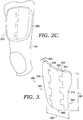
- a protective device 200 may comprise a first component 210 and a second component 220 joined along an interlocking edge connection 230.
- Protective device 200 may have a thickness 214 that may be constant or may vary at different locations on protective device 200.
- Protective device 200 may have a three-dimensional shape when component 210 and a second component 220 are assembled along interlocking edge connection 230. The three-dimensional shape of protective device 200 may be determined by the portion of a wearer's anatomy to be protected by protective device 200.
- the three dimensional shape of protective device 200 may comprise a complex curve in three dimensions to conform to the portion of the wearer's anatomy to be protected by protective device 200.
- the first component 210 may conform to a sub-portion of the anatomy to be protected by protective device 200
- the second component 220 may conform to a second sub-portion of the anatomy to be protected by protective device 200.
- first component 210 may conform to a medial portion of a thigh 290 while second component 220 may conform to a lateral portion of a thigh 290.
- the dimensions of the assembled protective device 200 and any and all components may also vary based upon the type of material used, the portion of a wearer's anatomy to be protected when the device is worn, the sport for which the protective device is to be used, the gender/size/position played by the athlete wearing the device, the types of impacts intended to be protected against, etc.
- appropriate dimensions for an assembled protective device in accordance with the present invention may be between approximately 15 and 20 centimeters from top to bottom in an as worn position, between approximately 10 and 22 centimeters from side to side in an as worn position, and up to several millimeters in thickness.
- protective device 200 has a concave side 270 and a convex side 280.
- concave side 270 may partially enclose the thigh of a wearer, either directly or indirectly.
- Protective device 200 may be retained in position to protect the desired anatomical portion of a wearer using garments, sleeves, tape, adhesives, straps, or any other mechanism.
- first component 210 may be used to form first component 210, second component 220, and any additional components used to form an interlocking protective device in accordance with the present invention.
- suitable materials are various nylons, acrylonitrile butadiene styrene (ABS), polypropylene, copolyesters, moldable carbon fibers, plastics, rubbers, composites, and the like.
- the example protective device 300 comprises a first component 310, a second component 320, and a third component 330.
- a first interlocking edge connection 340 may join first component 310 to second component 220, while a second interlocking edge connection 350 may join second component 320 to third component 330.
- protective device 300 possesses a top terminal edge 391 and a bottom terminal edge 392 comprised of a portion of each of first component 310, second component 320, and third component 330.
- protective device 300 possesses a first side edge 393 comprised entirely of first component 310 and a second side edge 394 comprised entirely of third component 330.
- protective device may have a height 301 and a width 302 conforming to the anatomical portion to be protected when the device 300 is worn, while device may have a thickness 303 selected based upon the material(s) used and the types of impacts anticipated while the device 300 is worn.
- interlocking edge connections that extend in a substantially vertical fashion
- other types of interlocking edge connections may be utilized for protective devices in accordance with the present invention.
- interlocking edge connections may extend substantially horizontally, diagonally, or in an irregular fashion.
- different orientations of interlocking edge connections may be used to join different components of a single protective device in accordance with the present invention.
- Interlocking edge 431 of first component 410 may comprise a plurality of tabs 412 and a plurality of notches 413 that mate with a plurality of tabs 422 and a plurality of notches 423 that comprise interlocking edge 432 of second component 420.
- the mating of the first interlocking edge 431 of the first component 410 with the second interlocking edge 432 of the second component 420 may form an interlocking edge connection when protective device 400 is assembled.
- Protective device 400 may have an assembled height 401 of between approximately 15-20 centimeters, an assembled width 402 of approximately 10-22 centimeters, and a thickness 403 of approximately 1-5 millimeters.
- Each tab 412, 422 may extend a length 404 from an adjoining notch 413, 423.
- Tab length 404 may be approximately 2 centimeters, or within a range of about 1-3 centimeters for the present example.
- first interlocking edge 431 and second interlocking edge 432 may secure first component 410 to second component 420.
- the connection between first component 410 and second component 420 may be further enhanced by a property referred to as 'stiction,' whereby materials in contact resist moving laterally with one another.
- the materials selected to form the components of a protective device in accordance with the present invention may, in some examples, comprise materials with high stiction properties.
- copolyesters may have particularly desirable stiction properties for use in protective devices in accordance with the present invention.
- One example of a suitable copolyester is available from Eastman Chemical Company under the trade name TRITAN.
- an interlocking edge connection between a first component 410, a second component 420, or any number of components utilized in a protective device in accordance with the present invention may be enhanced by the structure, such as a pocket, that retains a protective device over the portion of the wearer's anatomy to be protected.
- the presence of an interlocking edge connection, rather than a single continuous component, may provide a degree of flexibility along the interlocking edge connection, thereby enhancing the comfort and mobility of the wearer.
- first component 510 has a first interlocking edge 531 comprising a plurality of tabs 512 and a plurality of notches 533.
- Second component 520 has an interlocking edge 532 comprising a plurality of tabs 522 and a plurality of notches 523 that mate with the corresponding tabs 512 and notches 533 of the first interlocking edge 531 of the first component 510.
- tabs 512 may have a thickness 591 corresponding to a notch thickness 592 that is less than the thickness 590 of first component 510 and second component 520.
- Tab thickness 591 may be at least as thick as backer thickness 593, and tab thickness 591 may be greater than, for example by fifty percent, backer thickness 593.
- first interlocking edge 531 and second interlocking edge 532 may engage along three dimensions to provide a stronger interlocking edge connection between first component 510 and second component 520 than may be attainable without backers 570.
- backers may be additionally provided in notches 533 of first interlocking edge 531. If used, backers need not be present for all of the notches of a given interlocking edge.
- Protective device 600 may comprise a first component 610 joined vertically to a second component 620 by connecting edge 660.
- Second component 620 may further connect laterally to fourth component 640 by connecting edge 670
- fourth component 640 may join vertically to third component 630 by connecting edge 680.
- first component 610, second component 620, third component 630, and fourth component 640 may connect via connecting edges 660, 670, 680 to leave a gap 690 between first component 610 and third component 630 to permit the assembled protective device 600 to flex and bend more during use than might be the case without a gap 690.
- a gap 690 may be used with any number of components and/or connecting edges rather than the four illustrated in the example of FIG. 6 , and any gap provided in accordance with the present invention may have a different shape, orientation, and size relative to the protective device than the example illustrated in FIG. 6 .
- Further components of a protective device 600 beyond the four illustrated in the example shown in FIG. 6 may be assembled into a single protective device. Further, any number of gaps may be provided in the assembled protective device to enhance the flexibility of the protective device.
- Protective device 700 may comprise a first component 710 having a first hinge assembly 712 that mates with a second hinge assembly 722 of a second component 720.
- a pin 730 may be insertable through the mated first hinge component 712 and the second hinge component 722 to flexibly affix first component 710 and second component 720.
- the relative location, orientation, and/or size of a hinge used to affix components of a protective device in accordance with the present invention may vary from that illustrated in this example. Further, more than a single hinge may be used to flexibly affix any number of components to assemble a protective device in accordance with the present invention.
- Protective device 800 may comprise a first component 810 joined to a second component 820 by joining at least one ball 812 with at least one socket 822 to provide a flexible connection. More than a single ball and socket joint may be used in a protective device in accordance with the present invention, and one or more ball and socket joints may be used with connecting edges that are straight (as illustrated in FIG. 8 ), shaped in whole or in part as described in other examples herein, or shaped in any other way. The number of individual components joined using ball and socket joints may exceed the two illustrated in the example of FIG. 8 . Further, the location of a ball and socket joint may differ from that shown, and may have different sizes, locations, and/or orientations relative to components of a protective device than what is shown in the present example.
- Protective devices in accordance with the present invention may be formed in a variety of fashions.
- an entire protective device may be formed via molding, machining, additive manufacturing processes, or any other technique and then cut (for example, with a saw, knife, or die) to form components with interconnecting edges.
- individual components with desired interconnecting edges may be formed via molding, machining, additive manufacturing processes, etc.
- Interlocking edges for components of protective devices may have a variety of configurations beyond those described in the examples herein. Interlocking edges may comprise triangular tabs, posts and grooves, more complicated three dimensional structures than the examples provided, etc. Different degrees of protection desired, different anatomical portions to be protected, different types of sports, and/or different ability levels of athletes may benefit from different configurations of interlocking edges, different materials, and/or different configurations of protective devices in accordance with the scope of the present invention which is defined in the claims.
Landscapes
- Health & Medical Sciences (AREA)
- General Health & Medical Sciences (AREA)
- Physical Education & Sports Medicine (AREA)
- Engineering & Computer Science (AREA)
- Textile Engineering (AREA)
- Environmental & Geological Engineering (AREA)
- Professional, Industrial, Or Sporting Protective Garments (AREA)
Claims (15)
- Ineinandergreifende Schutzvorrichtung (200) um einen Abschnitt der Anatomie des Trägers zu schützen, wobei die ineinandergreifende Schutzvorrichtung umfasst:eine erste Komponente, die sich in drei Dimensionen erstreckt und eingerichtet ist, um sich an einen ersten Teilabschnitt des Abschnittes der Anatomie des Trägers anzupassen, wobei die erste Komponente (210) mindestens eine erste ineinandergreifende Kante mit einer ersten Vielzahl an Vorsprüngen (412) und Aussparungen (413) aufweist und Vorsprungsverstärker (570) aufweist, die in den Aussparungen und zwischen den Vorsprüngen der ersten ineinandergreifenden Kante positioniert sind, wobei die Vorsprungsverstärker nicht für alle der Aussparungen der ersten ineinandergreifenden Kante vorliegen müssen; undeine zweite Komponente (220), die sich in drei Dimensionen erstreckt und gestaltet ist, um sich an einen zweiten Teilabschnitt des Abschnittes der Anatomie des Trägers anzupassen, wobei die zweite Komponente mindestens eine zweite ineinandergreifende Kante mit einer zweiten Vielzahl an Vorsprüngen (422) und Aussparungen (423) aufweist, die mit der ersten Vielzahl an Vorsprüngen und Aussparungen ineinandergreifen, um eine ineinandergreifende Kantenverbindung (230) zu bilden, welche die zweite Komponente an der ersten Komponente festhält, so dass die erste Komponente und die zweiten Komponente eingerichtet sind, um sich dem ersten Teilabschnitt und dem zweiten Teilabschnitt des Abschnittes der Anatomie des Trägers anzupassen, wenn die ineinandergreifenden Schutzvorrichtung getragen wird; undwobei die Vorsprünge der zweiten ineinandergreifenden Kante in die Aussparungen und zwischen die Vorsprünge der ersten ineinandergreifenden Kante passen und mit den Vorsprungsverstärkern eingreifen.
- Ineinandergreifende Schutzvorrichtung nach Anspruch 1, wobei die zweite Komponente eine erste Dicke einschließt und der Vorsprung der zweiten Vielzahl an Vorsprüngen eine zweite Dicke einschließt, die dünner als die erste Dicke ist.
- Ineinandergreifende Schutzvorrichtung nach Anspruch 1, weiter umfassend eine dritte Komponente (330), die sich in drei Dimensionen erstreckt, um sich an einen dritten Teilabschnitt der Anatomie des Trägers anzupassen, und wobei: die dritte Komponente weiter eine dritte ineinandergreifende Kante mit einer dritten Vielzahl an Vorsprüngen und Aussparungen umfasst, die mit einer vierten ineinandergreifenden Kante der zweiten Komponente zusammenpassen, die eine vierte Vielzahl an Vorsprüngen und Aussparungen aufweist, die mit der dritten Vielzahl an Vorsprüngen und Aussparungen der dritten ineinandergreifenden Kante zusammenpassen, um eine zweiten ineinandergreifende Kantenverbindung (350) zu bilden.
- Ineinandergreifende Schutzvorrichtung nach Anspruch 3, wobei die erste ineinandergreifende Kantenverbindung und die zweite ineinandergreifende Kantenverbindung sich in eine vertikale Ausrichtung in Bezug zueinander erstrecken.
- Ineinandergreifende Schutzvorrichtung nach Anspruch 3, wobei die dritte Komponente in einem Abstand von der ersten Komponente ist.
- Ineinandergreifende Schutzvorrichtung nach Anspruch 1, wobei die erste Komponente und die zweite Komponente aus einem Copolyester hergestellt sind.
- Ineinandergreifende Schutzvorrichtung nach Anspruch 1, wobei die erste Komponente und die zweite Komponente aus Nylon hergestellt sind.
- Ineinandergreifende Schutzvorrichtung nach Anspruch 1, wobei die erste Komponente und die zweite Komponente aus Acrylonitril-Butadien-Styrol hergestellt sind.
- Ineinandergreifende Schutzvorrichtung nach Anspruch 1, wobei die erste Komponente und die zweite Komponente aus Polypropylen hergestellt sind.
- Ineinandergreifende Schutzvorrichtung nach Anspruch 1, wobei die erste Komponente und die zweite Komponente aus formbaren Kohlefasern hergestellt sind.
- Ineinandergreifende Schutzvorrichtung nach Anspruch 1, wobei die erste ineinandergreifende Kante und die zweite ineinandergreifende Kante durch das Schneiden der ersten Komponente und der zweiten Komponente aus einem einstückig gebildeten Stück mit der Größe, Form, und Gestaltung der vorgesehenen zusammengesetzten ineinandergreifenden Schutzvorrichtung gebildet werden.
- Ineinandergreifende Schutzvorrichtung nach Anspruch 11, wobei das einstückig gebildete Stück durch Formen gebildet wird.
- Ineinandergreifende Schutzvorrichtung nach Anspruch 11, wobei das einstückig gebildete Stück durch einen additiven Herstellungsprozess gebildet wird.
- Ineinandergreifende Schutzvorrichtung nach Anspruch 1, wobei die erste Komponente und die zweite Komponente einzeln gebildet werden.
- Ineinandergreifende Schutzvorrichtung nach Anspruch 1, wobei die zweite Komponente eine dritte ineinandergreifende Kante mit einer dritten Vielzahl an Vorsprüngen und Einsparungen einschließt; und die weiter eine dritte Komponente umfasst, die eine vierte ineinandergreifende Kante mit einer vierten Vielzahl an Vorsprüngen und Aussparungen einschließt, die mit der dritten ineinandergreifenden Kante der zweiten Komponente zusammenpasst, um eine zweite ineinandergreifende Kantenverbindung zu bilden, wobei die dritte Komponente eine fünfte ineinandergreifende Kante mit einer fünften Vielzahl an Vorsprüngen und Aussparungen einschließt; und
eine vierte Komponente (640) eine sechste ineinandergreifende Kante mit einer sechsten Vielzahl an Vorsprüngen und Aussparungen einschließt, die mit der fünften ineinandergreifenden Kante der dritten Komponente zusammenpassen, um eine dritte ineinandergreifende Kantenverbindung zu bilden, wobei die vierte Komponente an einer Position mit Abstand von der ersten Komponente gehalten wird.
Applications Claiming Priority (2)
| Application Number | Priority Date | Filing Date | Title |
|---|---|---|---|
| US13/834,299 US20140259327A1 (en) | 2013-03-15 | 2013-03-15 | Interlocking Impact Protection System For Contact Sports |
| PCT/US2014/021910 WO2014150027A1 (en) | 2013-03-15 | 2014-03-07 | Interlocking impact protection system for contact sports |
Publications (3)
| Publication Number | Publication Date |
|---|---|
| EP2967164A1 EP2967164A1 (de) | 2016-01-20 |
| EP2967164A4 EP2967164A4 (de) | 2016-10-19 |
| EP2967164B1 true EP2967164B1 (de) | 2020-02-12 |
Family
ID=51520430
Family Applications (1)
| Application Number | Title | Priority Date | Filing Date |
|---|---|---|---|
| EP14769077.0A Active EP2967164B1 (de) | 2013-03-15 | 2014-03-07 | Ineinandergreifendes aufprallschutzsystem für kontaktsportarten |
Country Status (4)
| Country | Link |
|---|---|
| US (1) | US20140259327A1 (de) |
| EP (1) | EP2967164B1 (de) |
| CN (1) | CN105050438B (de) |
| WO (1) | WO2014150027A1 (de) |
Families Citing this family (13)
| Publication number | Priority date | Publication date | Assignee | Title |
|---|---|---|---|---|
| US12268264B2 (en) | 2010-12-31 | 2025-04-08 | Adrienne Yeung | Conformal protective head wear |
| US10952484B2 (en) | 2016-09-01 | 2021-03-23 | Adrienne Yeung | Conformal protective head wear |
| US10701991B2 (en) | 2013-03-12 | 2020-07-07 | Nike, Inc. | Articulated protective apparatus |
| US10201206B2 (en) * | 2014-02-20 | 2019-02-12 | Kranos Ip Corporation | Lacrosse helmet |
| US20160021966A1 (en) * | 2014-02-20 | 2016-01-28 | Kranos Ip Corporation | Lacrosse helmet |
| EP3125712A4 (de) * | 2014-04-01 | 2017-11-29 | Bell Sports Inc. | Arretierungsauskleidung für helm |
| US9925440B2 (en) | 2014-05-13 | 2018-03-27 | Bauer Hockey, Llc | Sporting goods including microlattice structures |
| CN113325664B (zh) | 2014-12-23 | 2024-07-19 | 普利司通美国轮胎运营有限责任公司 | 聚合物产品的增材制造方法 |
| EP3175895B1 (de) * | 2015-12-01 | 2018-10-24 | NIKE Innovate C.V. | Bewegliche schutzvorrichtung |
| EP3390006B1 (de) | 2015-12-17 | 2021-01-27 | Bridgestone Americas Tire Operations, LLC | Kartuschen zur generativen fertigung und verfahren zur herstellung gehärteter polymerprodukte durch generative fertigung |
| JP6496343B2 (ja) * | 2016-05-10 | 2019-04-03 | 有限会社小林プラスチック製作所 | ニースライダー |
| WO2018081053A1 (en) | 2016-10-27 | 2018-05-03 | Bridgestone Americas Tire Operations, Llc | Processes for producing cured polymeric products by additive manufacturing |
| US11684104B2 (en) | 2019-05-21 | 2023-06-27 | Bauer Hockey Llc | Helmets comprising additively-manufactured components |
Family Cites Families (19)
| Publication number | Priority date | Publication date | Assignee | Title |
|---|---|---|---|---|
| US2057942A (en) * | 1935-01-29 | 1936-10-20 | Fay Marc Aurele Alfred | Toy construction unit |
| US2237892A (en) * | 1939-03-27 | 1941-04-08 | Squire Jacob | Sock lining |
| US2369531A (en) * | 1942-10-06 | 1945-02-13 | Caltabiano Robert | Shoe and outsole therefor |
| US4287693A (en) * | 1980-03-26 | 1981-09-08 | Pawling Rubber Corporation | Interlocking rubber mat |
| JPS6036081Y2 (ja) * | 1982-06-26 | 1985-10-26 | 美津濃株式会社 | 靴の中敷 |
| US4479269A (en) * | 1982-12-09 | 1984-10-30 | Rubatex Corporation | Athletic padding |
| US5161257A (en) * | 1992-03-13 | 1992-11-10 | Stromgren Supports, Inc. | Football gridle |
| US5330806A (en) * | 1992-07-13 | 1994-07-19 | Bythewood Daniel W | Puzzle towel/mat for bath, beach and kitchen |
| US6142848A (en) * | 1992-08-28 | 2000-11-07 | Geo Australia Pty. Limited | Educational toy components |
| US5395683A (en) * | 1993-03-26 | 1995-03-07 | Alliedsignal Inc. | Protective pad |
| US6109329A (en) * | 1998-08-28 | 2000-08-29 | Russo; Ralph | Modular panel structure |
| US6453973B1 (en) * | 1998-08-28 | 2002-09-24 | Ralph Russo | Modular panel structure |
| US6665993B2 (en) * | 2002-05-07 | 2003-12-23 | Sorensen Research And Development Trust | Interlockable element for structure assembly set |
| DE202005018902U1 (de) * | 2005-12-02 | 2007-04-12 | Bauerfeind Ag | Einlegesohle für Schuhe |
| EP2359288B1 (de) * | 2008-11-09 | 2019-06-05 | 3D Systems, Inc. | Massgeschneiderte klammern, gipsverbände sowie vorrichtungen und verfahren für entwurf und herstellung |
| US8613716B2 (en) * | 2008-11-09 | 2013-12-24 | 3D Systems, Inc. | Custom braces, casts and devices having limited flexibility and methods for designing and fabricating |
| US8070382B2 (en) * | 2009-05-01 | 2011-12-06 | Unity Creations, Ltd. | Interlocking rubber tiles for playgrounds |
| US8443468B2 (en) * | 2011-01-31 | 2013-05-21 | Matthew Alan Minson | Cervical spine protection collar for contact and non-contact activities |
| US8500669B2 (en) * | 2012-01-05 | 2013-08-06 | Wellpower Sporting Goods Co., Ltd. | Protective cup |
-
2013
- 2013-03-15 US US13/834,299 patent/US20140259327A1/en not_active Abandoned
-
2014
- 2014-03-07 WO PCT/US2014/021910 patent/WO2014150027A1/en not_active Ceased
- 2014-03-07 EP EP14769077.0A patent/EP2967164B1/de active Active
- 2014-03-07 CN CN201480014948.0A patent/CN105050438B/zh active Active
Non-Patent Citations (1)
| Title |
|---|
| None * |
Also Published As
| Publication number | Publication date |
|---|---|
| EP2967164A1 (de) | 2016-01-20 |
| EP2967164A4 (de) | 2016-10-19 |
| CN105050438B (zh) | 2018-03-27 |
| CN105050438A (zh) | 2015-11-11 |
| WO2014150027A1 (en) | 2014-09-25 |
| US20140259327A1 (en) | 2014-09-18 |
Similar Documents
| Publication | Publication Date | Title |
|---|---|---|
| US20140259327A1 (en) | Interlocking Impact Protection System For Contact Sports | |
| US9539487B2 (en) | Multi-material impact protection for contact sports | |
| US6519781B1 (en) | Energy absorbing protective device that protects areas of articulation | |
| US10687566B2 (en) | Modular impact protection system for athletic wear | |
| US12311249B2 (en) | Protective pad for protection from impact and a protective garment using the same | |
| EP2967166B1 (de) | Bewegliche schutzvorrichtung | |
| US20120240317A1 (en) | Protective athletic garment | |
| US20140208492A1 (en) | Garment with integrated protective padding | |
| US11103766B2 (en) | Removable pad arrangement | |
| EP3370031B1 (de) | Mehrkomponentige aufprallschutzvorrichtung für sportler | |
| US20190281905A1 (en) | Padded Garment | |
| US20120164377A1 (en) | Sports pad | |
| EP3264928B1 (de) | Schutzabdeckung mit übergangskupplungsregion | |
| CN100534555C (zh) | 保护部件 | |
| US20160262465A1 (en) | Joint protector system | |
| US20200170317A1 (en) | Protective garment for female adult and youth sports participants | |
| KR20240123031A (ko) | 에어쿠션을 내장한 아이스하키 유니폼 | |
| CN122006221A (zh) | 保护头带 | |
| EP3016535B1 (de) | Modulares aufprallschutzsystem für athletische bekleidung | |
| WO2017118837A1 (en) | Lower leg garment |
Legal Events
| Date | Code | Title | Description |
|---|---|---|---|
| PUAI | Public reference made under article 153(3) epc to a published international application that has entered the european phase |
Free format text: ORIGINAL CODE: 0009012 |
|
| 17P | Request for examination filed |
Effective date: 20150917 |
|
| AK | Designated contracting states |
Kind code of ref document: A1 Designated state(s): AL AT BE BG CH CY CZ DE DK EE ES FI FR GB GR HR HU IE IS IT LI LT LU LV MC MK MT NL NO PL PT RO RS SE SI SK SM TR |
|
| AX | Request for extension of the european patent |
Extension state: BA ME |
|
| DAX | Request for extension of the european patent (deleted) | ||
| A4 | Supplementary search report drawn up and despatched |
Effective date: 20160921 |
|
| RIC1 | Information provided on ipc code assigned before grant |
Ipc: A41D 13/005 20060101AFI20160915BHEP Ipc: A63B 71/12 20060101ALI20160915BHEP |
|
| REG | Reference to a national code |
Ref country code: DE Ref legal event code: R079 Ref document number: 602014060923 Country of ref document: DE Free format text: PREVIOUS MAIN CLASS: A41D0013015000 Ipc: A41D0013005000 |
|
| GRAP | Despatch of communication of intention to grant a patent |
Free format text: ORIGINAL CODE: EPIDOSNIGR1 |
|
| RIC1 | Information provided on ipc code assigned before grant |
Ipc: A63B 71/12 20060101ALI20190204BHEP Ipc: A41D 13/005 20060101AFI20190204BHEP |
|
| STAA | Information on the status of an ep patent application or granted ep patent |
Free format text: STATUS: GRANT OF PATENT IS INTENDED |
|
| INTG | Intention to grant announced |
Effective date: 20190314 |
|
| GRAS | Grant fee paid |
Free format text: ORIGINAL CODE: EPIDOSNIGR3 |
|
| GRAJ | Information related to disapproval of communication of intention to grant by the applicant or resumption of examination proceedings by the epo deleted |
Free format text: ORIGINAL CODE: EPIDOSDIGR1 |
|
| GRAL | Information related to payment of fee for publishing/printing deleted |
Free format text: ORIGINAL CODE: EPIDOSDIGR3 |
|
| STAA | Information on the status of an ep patent application or granted ep patent |
Free format text: STATUS: REQUEST FOR EXAMINATION WAS MADE |
|
| INTC | Intention to grant announced (deleted) | ||
| GRAP | Despatch of communication of intention to grant a patent |
Free format text: ORIGINAL CODE: EPIDOSNIGR1 |
|
| STAA | Information on the status of an ep patent application or granted ep patent |
Free format text: STATUS: GRANT OF PATENT IS INTENDED |
|
| INTG | Intention to grant announced |
Effective date: 20190917 |
|
| GRAA | (expected) grant |
Free format text: ORIGINAL CODE: 0009210 |
|
| STAA | Information on the status of an ep patent application or granted ep patent |
Free format text: STATUS: THE PATENT HAS BEEN GRANTED |
|
| AK | Designated contracting states |
Kind code of ref document: B1 Designated state(s): AL AT BE BG CH CY CZ DE DK EE ES FI FR GB GR HR HU IE IS IT LI LT LU LV MC MK MT NL NO PL PT RO RS SE SI SK SM TR |
|
| REG | Reference to a national code |
Ref country code: GB Ref legal event code: FG4D |
|
| REG | Reference to a national code |
Ref country code: CH Ref legal event code: EP |
|
| REG | Reference to a national code |
Ref country code: AT Ref legal event code: REF Ref document number: 1230927 Country of ref document: AT Kind code of ref document: T Effective date: 20200215 |
|
| REG | Reference to a national code |
Ref country code: IE Ref legal event code: FG4D |
|
| REG | Reference to a national code |
Ref country code: DE Ref legal event code: R096 Ref document number: 602014060923 Country of ref document: DE |
|
| PG25 | Lapsed in a contracting state [announced via postgrant information from national office to epo] |
Ref country code: NO Free format text: LAPSE BECAUSE OF FAILURE TO SUBMIT A TRANSLATION OF THE DESCRIPTION OR TO PAY THE FEE WITHIN THE PRESCRIBED TIME-LIMIT Effective date: 20200512 Ref country code: RS Free format text: LAPSE BECAUSE OF FAILURE TO SUBMIT A TRANSLATION OF THE DESCRIPTION OR TO PAY THE FEE WITHIN THE PRESCRIBED TIME-LIMIT Effective date: 20200212 Ref country code: FI Free format text: LAPSE BECAUSE OF FAILURE TO SUBMIT A TRANSLATION OF THE DESCRIPTION OR TO PAY THE FEE WITHIN THE PRESCRIBED TIME-LIMIT Effective date: 20200212 |
|
| REG | Reference to a national code |
Ref country code: LT Ref legal event code: MG4D |
|
| REG | Reference to a national code |
Ref country code: NL Ref legal event code: MP Effective date: 20200212 |
|
| PG25 | Lapsed in a contracting state [announced via postgrant information from national office to epo] |
Ref country code: GR Free format text: LAPSE BECAUSE OF FAILURE TO SUBMIT A TRANSLATION OF THE DESCRIPTION OR TO PAY THE FEE WITHIN THE PRESCRIBED TIME-LIMIT Effective date: 20200513 Ref country code: BG Free format text: LAPSE BECAUSE OF FAILURE TO SUBMIT A TRANSLATION OF THE DESCRIPTION OR TO PAY THE FEE WITHIN THE PRESCRIBED TIME-LIMIT Effective date: 20200512 Ref country code: HR Free format text: LAPSE BECAUSE OF FAILURE TO SUBMIT A TRANSLATION OF THE DESCRIPTION OR TO PAY THE FEE WITHIN THE PRESCRIBED TIME-LIMIT Effective date: 20200212 Ref country code: LV Free format text: LAPSE BECAUSE OF FAILURE TO SUBMIT A TRANSLATION OF THE DESCRIPTION OR TO PAY THE FEE WITHIN THE PRESCRIBED TIME-LIMIT Effective date: 20200212 Ref country code: SE Free format text: LAPSE BECAUSE OF FAILURE TO SUBMIT A TRANSLATION OF THE DESCRIPTION OR TO PAY THE FEE WITHIN THE PRESCRIBED TIME-LIMIT Effective date: 20200212 Ref country code: IS Free format text: LAPSE BECAUSE OF FAILURE TO SUBMIT A TRANSLATION OF THE DESCRIPTION OR TO PAY THE FEE WITHIN THE PRESCRIBED TIME-LIMIT Effective date: 20200612 |
|
| PG25 | Lapsed in a contracting state [announced via postgrant information from national office to epo] |
Ref country code: NL Free format text: LAPSE BECAUSE OF FAILURE TO SUBMIT A TRANSLATION OF THE DESCRIPTION OR TO PAY THE FEE WITHIN THE PRESCRIBED TIME-LIMIT Effective date: 20200212 |
|
| PG25 | Lapsed in a contracting state [announced via postgrant information from national office to epo] |
Ref country code: PT Free format text: LAPSE BECAUSE OF FAILURE TO SUBMIT A TRANSLATION OF THE DESCRIPTION OR TO PAY THE FEE WITHIN THE PRESCRIBED TIME-LIMIT Effective date: 20200705 Ref country code: ES Free format text: LAPSE BECAUSE OF FAILURE TO SUBMIT A TRANSLATION OF THE DESCRIPTION OR TO PAY THE FEE WITHIN THE PRESCRIBED TIME-LIMIT Effective date: 20200212 Ref country code: DK Free format text: LAPSE BECAUSE OF FAILURE TO SUBMIT A TRANSLATION OF THE DESCRIPTION OR TO PAY THE FEE WITHIN THE PRESCRIBED TIME-LIMIT Effective date: 20200212 Ref country code: CZ Free format text: LAPSE BECAUSE OF FAILURE TO SUBMIT A TRANSLATION OF THE DESCRIPTION OR TO PAY THE FEE WITHIN THE PRESCRIBED TIME-LIMIT Effective date: 20200212 Ref country code: RO Free format text: LAPSE BECAUSE OF FAILURE TO SUBMIT A TRANSLATION OF THE DESCRIPTION OR TO PAY THE FEE WITHIN THE PRESCRIBED TIME-LIMIT Effective date: 20200212 Ref country code: EE Free format text: LAPSE BECAUSE OF FAILURE TO SUBMIT A TRANSLATION OF THE DESCRIPTION OR TO PAY THE FEE WITHIN THE PRESCRIBED TIME-LIMIT Effective date: 20200212 Ref country code: SM Free format text: LAPSE BECAUSE OF FAILURE TO SUBMIT A TRANSLATION OF THE DESCRIPTION OR TO PAY THE FEE WITHIN THE PRESCRIBED TIME-LIMIT Effective date: 20200212 Ref country code: LT Free format text: LAPSE BECAUSE OF FAILURE TO SUBMIT A TRANSLATION OF THE DESCRIPTION OR TO PAY THE FEE WITHIN THE PRESCRIBED TIME-LIMIT Effective date: 20200212 Ref country code: SK Free format text: LAPSE BECAUSE OF FAILURE TO SUBMIT A TRANSLATION OF THE DESCRIPTION OR TO PAY THE FEE WITHIN THE PRESCRIBED TIME-LIMIT Effective date: 20200212 |
|
| REG | Reference to a national code |
Ref country code: CH Ref legal event code: PL |
|
| REG | Reference to a national code |
Ref country code: DE Ref legal event code: R097 Ref document number: 602014060923 Country of ref document: DE |
|
| REG | Reference to a national code |
Ref country code: AT Ref legal event code: MK05 Ref document number: 1230927 Country of ref document: AT Kind code of ref document: T Effective date: 20200212 |
|
| PG25 | Lapsed in a contracting state [announced via postgrant information from national office to epo] |
Ref country code: MC Free format text: LAPSE BECAUSE OF FAILURE TO SUBMIT A TRANSLATION OF THE DESCRIPTION OR TO PAY THE FEE WITHIN THE PRESCRIBED TIME-LIMIT Effective date: 20200212 |
|
| PLBE | No opposition filed within time limit |
Free format text: ORIGINAL CODE: 0009261 |
|
| STAA | Information on the status of an ep patent application or granted ep patent |
Free format text: STATUS: NO OPPOSITION FILED WITHIN TIME LIMIT |
|
| REG | Reference to a national code |
Ref country code: BE Ref legal event code: MM Effective date: 20200331 |
|
| PG25 | Lapsed in a contracting state [announced via postgrant information from national office to epo] |
Ref country code: LU Free format text: LAPSE BECAUSE OF NON-PAYMENT OF DUE FEES Effective date: 20200307 |
|
| 26N | No opposition filed |
Effective date: 20201113 |
|
| PG25 | Lapsed in a contracting state [announced via postgrant information from national office to epo] |
Ref country code: AT Free format text: LAPSE BECAUSE OF FAILURE TO SUBMIT A TRANSLATION OF THE DESCRIPTION OR TO PAY THE FEE WITHIN THE PRESCRIBED TIME-LIMIT Effective date: 20200212 Ref country code: IT Free format text: LAPSE BECAUSE OF FAILURE TO SUBMIT A TRANSLATION OF THE DESCRIPTION OR TO PAY THE FEE WITHIN THE PRESCRIBED TIME-LIMIT Effective date: 20200212 Ref country code: LI Free format text: LAPSE BECAUSE OF NON-PAYMENT OF DUE FEES Effective date: 20200331 Ref country code: CH Free format text: LAPSE BECAUSE OF NON-PAYMENT OF DUE FEES Effective date: 20200331 Ref country code: IE Free format text: LAPSE BECAUSE OF NON-PAYMENT OF DUE FEES Effective date: 20200307 |
|
| PG25 | Lapsed in a contracting state [announced via postgrant information from national office to epo] |
Ref country code: PL Free format text: LAPSE BECAUSE OF FAILURE TO SUBMIT A TRANSLATION OF THE DESCRIPTION OR TO PAY THE FEE WITHIN THE PRESCRIBED TIME-LIMIT Effective date: 20200212 Ref country code: BE Free format text: LAPSE BECAUSE OF NON-PAYMENT OF DUE FEES Effective date: 20200331 Ref country code: SI Free format text: LAPSE BECAUSE OF FAILURE TO SUBMIT A TRANSLATION OF THE DESCRIPTION OR TO PAY THE FEE WITHIN THE PRESCRIBED TIME-LIMIT Effective date: 20200212 |
|
| PG25 | Lapsed in a contracting state [announced via postgrant information from national office to epo] |
Ref country code: TR Free format text: LAPSE BECAUSE OF FAILURE TO SUBMIT A TRANSLATION OF THE DESCRIPTION OR TO PAY THE FEE WITHIN THE PRESCRIBED TIME-LIMIT Effective date: 20200212 Ref country code: MT Free format text: LAPSE BECAUSE OF FAILURE TO SUBMIT A TRANSLATION OF THE DESCRIPTION OR TO PAY THE FEE WITHIN THE PRESCRIBED TIME-LIMIT Effective date: 20200212 Ref country code: CY Free format text: LAPSE BECAUSE OF FAILURE TO SUBMIT A TRANSLATION OF THE DESCRIPTION OR TO PAY THE FEE WITHIN THE PRESCRIBED TIME-LIMIT Effective date: 20200212 |
|
| PG25 | Lapsed in a contracting state [announced via postgrant information from national office to epo] |
Ref country code: MK Free format text: LAPSE BECAUSE OF FAILURE TO SUBMIT A TRANSLATION OF THE DESCRIPTION OR TO PAY THE FEE WITHIN THE PRESCRIBED TIME-LIMIT Effective date: 20200212 Ref country code: AL Free format text: LAPSE BECAUSE OF FAILURE TO SUBMIT A TRANSLATION OF THE DESCRIPTION OR TO PAY THE FEE WITHIN THE PRESCRIBED TIME-LIMIT Effective date: 20200212 |
|
| P01 | Opt-out of the competence of the unified patent court (upc) registered |
Effective date: 20230515 |
|
| PGFP | Annual fee paid to national office [announced via postgrant information from national office to epo] |
Ref country code: FR Payment date: 20251231 Year of fee payment: 13 |
|
| PGFP | Annual fee paid to national office [announced via postgrant information from national office to epo] |
Ref country code: GB Payment date: 20260106 Year of fee payment: 13 |
|
| PGFP | Annual fee paid to national office [announced via postgrant information from national office to epo] |
Ref country code: DE Payment date: 20260102 Year of fee payment: 13 |