EP3370031B1 - Mehrkomponentige aufprallschutzvorrichtung für sportler - Google Patents
Mehrkomponentige aufprallschutzvorrichtung für sportler Download PDFInfo
- Publication number
- EP3370031B1 EP3370031B1 EP18162759.7A EP18162759A EP3370031B1 EP 3370031 B1 EP3370031 B1 EP 3370031B1 EP 18162759 A EP18162759 A EP 18162759A EP 3370031 B1 EP3370031 B1 EP 3370031B1
- Authority
- EP
- European Patent Office
- Prior art keywords
- protective
- plates
- protective plate
- connection points
- impact absorbing
- Prior art date
- Legal status (The legal status is an assumption and is not a legal conclusion. Google has not performed a legal analysis and makes no representation as to the accuracy of the status listed.)
- Active
Links
Images



Classifications
-
- A—HUMAN NECESSITIES
- A41—WEARING APPAREL
- A41D—OUTERWEAR; PROTECTIVE GARMENTS; ACCESSORIES
- A41D13/00—Professional, industrial or sporting protective garments, e.g. surgeons' gowns or garments protecting against blows or punches
- A41D13/015—Professional, industrial or sporting protective garments, e.g. surgeons' gowns or garments protecting against blows or punches with shock-absorbing means
-
- A—HUMAN NECESSITIES
- A63—SPORTS; GAMES; AMUSEMENTS
- A63B—APPARATUS FOR PHYSICAL TRAINING, GYMNASTICS, SWIMMING, CLIMBING, OR FENCING; BALL GAMES; TRAINING EQUIPMENT
- A63B71/00—Games or sports accessories not covered in groups A63B1/00 - A63B69/00
- A63B71/08—Body-protectors for players or sportsmen, i.e. body-protecting accessories affording protection of body parts against blows or collisions
- A63B71/12—Body-protectors for players or sportsmen, i.e. body-protecting accessories affording protection of body parts against blows or collisions for the body or the legs, e.g. for the shoulders
-
- A—HUMAN NECESSITIES
- A63—SPORTS; GAMES; AMUSEMENTS
- A63B—APPARATUS FOR PHYSICAL TRAINING, GYMNASTICS, SWIMMING, CLIMBING, OR FENCING; BALL GAMES; TRAINING EQUIPMENT
- A63B71/00—Games or sports accessories not covered in groups A63B1/00 - A63B69/00
- A63B71/08—Body-protectors for players or sportsmen, i.e. body-protecting accessories affording protection of body parts against blows or collisions
- A63B71/12—Body-protectors for players or sportsmen, i.e. body-protecting accessories affording protection of body parts against blows or collisions for the body or the legs, e.g. for the shoulders
- A63B71/1225—Body-protectors for players or sportsmen, i.e. body-protecting accessories affording protection of body parts against blows or collisions for the body or the legs, e.g. for the shoulders for the legs, e.g. thighs, knees, ankles, feet
- A63B2071/1241—Body-protectors for players or sportsmen, i.e. body-protecting accessories affording protection of body parts against blows or collisions for the body or the legs, e.g. for the shoulders for the legs, e.g. thighs, knees, ankles, feet for the thigh
-
- A—HUMAN NECESSITIES
- A63—SPORTS; GAMES; AMUSEMENTS
- A63B—APPARATUS FOR PHYSICAL TRAINING, GYMNASTICS, SWIMMING, CLIMBING, OR FENCING; BALL GAMES; TRAINING EQUIPMENT
- A63B71/00—Games or sports accessories not covered in groups A63B1/00 - A63B69/00
- A63B71/08—Body-protectors for players or sportsmen, i.e. body-protecting accessories affording protection of body parts against blows or collisions
- A63B71/12—Body-protectors for players or sportsmen, i.e. body-protecting accessories affording protection of body parts against blows or collisions for the body or the legs, e.g. for the shoulders
- A63B71/1225—Body-protectors for players or sportsmen, i.e. body-protecting accessories affording protection of body parts against blows or collisions for the body or the legs, e.g. for the shoulders for the legs, e.g. thighs, knees, ankles, feet
- A63B2071/125—Body-protectors for players or sportsmen, i.e. body-protecting accessories affording protection of body parts against blows or collisions for the body or the legs, e.g. for the shoulders for the legs, e.g. thighs, knees, ankles, feet for the knee
-
- A—HUMAN NECESSITIES
- A63—SPORTS; GAMES; AMUSEMENTS
- A63B—APPARATUS FOR PHYSICAL TRAINING, GYMNASTICS, SWIMMING, CLIMBING, OR FENCING; BALL GAMES; TRAINING EQUIPMENT
- A63B2209/00—Characteristics of used materials
Definitions
- the present invention relates to athletic safety and injury prevention. More particularly, the present invention relates to an impact protection device to be worn by an athlete participating in a contact sport, such as American football.
- EP1517111 A2 discloses a device comprising a plurality of disks milled in a plurality of places. Each milled place having a radius of curvature approximately equal to the radius of curvature of the disk.
- the disks are laid out in an imbricated pattern row by row such that each disk in a row is in substantially a straight line with the other disks in the row and overlaps a milled place of a disk in a row above its row and has its milled place overlapped by a disk in the row below its row.
- US2007/0234458 discloses a composite ballistic material having one or more layers of flexible ballistic fabric and a plurality of scales disposed in an overlapping configuration.
- a protective device in accordance with the present invention provides improved impact protection for athletes participating in contact sports such as American football, soccer (world football), hockey, lacrosse, or any other contact sport permitting participants to wear protective gear.
- a protective device in accordance with the present invention may be particularly suitable for protecting large muscle areas of the wearer from impact, but may be used to protect other portions of a wearer's anatomy without the party from the scope of the present invention.
- One example of a large muscle area that may be protected using a device in accordance with the present invention are the thighs of an American football player.
- a protective device in accordance with the present invention may comprise a plurality of protective plates arranged in an overlapping fashion and retained over the portion of the wearer's anatomy to be protected from impact.
- Protective plates of a protective device in accordance with the present invention may have a variety of shapes and may be substantially planar, may curve in two dimensions, or may curve in three dimensions.
- the protective plates may comprise any type of material that can absorb an impact and dissipate the force of that impact across a wider surface area than the impact contact point.
- Protective plates may be formed of various types of nylon, polypropylene, acrylonitrile butadiene styrene (ABS), and/or other relatively hard, resilient materials. Alternatively, softer compressible materials such as rubber and/or foams may be used.
- protective plates used in a protective device in accordance with the present invention may comprise compressible foams, gels or the like encased in a resilient membrane or shell, which may be made from a nylon, polypropylene, acrylonitrile, butadiene styrene, etc.
- protective plates used in accordance with the present invention may comprise multiple layers of materials possessing different properties, such as an outward facing hard layer and a skin facing soft layer. Any number of layers may be used in a protective plate in accordance with the present invention.
- the material used in a protective plate may also vary laterally and/or vertically along the surface of the plate, for example to provide different types and/or degrees of protection at different locations on the wearer's anatomy.
- the protective plates retained in an overlapping fashion in a protective device in accordance with the present invention are retained by having connection points that mate with connection points on other protective plates to permit the protective plates to be assembled and retained in an overlapping fashion over the portion of the wearer's anatomy to be protected.
- An athletic garment such as pants or a shirt, may provide pockets that may receive assembled protective plates to facilitate the retention of the overlapping protective plates over the portion of the wearer's anatomy to be protected and to facilitate the overlapping protective plates conformation to the wearer's anatomy.
- Overlapping protective plates in accordance with the present invention may further provide ventilation to enhance the comfort and temperature regulation of the wearer. Ventilation may be provided by shaping and/or arranging the protective plates to provide gaps between at least portions of the over lapping protective plates. Additionally/alternatively, openings such as slits, holes, or perforations may be provided within the protective plates themselves to permit the ready flow of air through the protective device formed by the assembled overlapping protective plates.
- FIG. 1 an athlete 100 wearing protective gear is illustrated.
- the athlete 100 is an American football player, but athletes participating in any other contact sport may likewise benefit from protective devices in accordance with the present invention.
- Player 100 is shown wearing a helmet 110 and shoulder pads 120 beneath a jersey 102.
- player 100 is also wearing chest protection 130, which may comprise a flak jacket or similar item, and abdominal protection 140 beneath jersey 102.
- Player is further illustrated wearing a right elbow pad 150 and a left elbow pad 152.
- Player 100 is also wearing a right thigh pad 160 and a left thigh pad 162 and a right knee pad 170 and a left knee pad 172 beneath pants 104.
- Pants 104 may have pockets (not shown) on either the outside or, more typically, the inside to retain pads such as thigh pads 160, 162 and knee pads 170, 172. Player 100 is further shown wearing shoes 108 and socks 106. While not currently typical in American football, socks 106 may retain additional pads such as a shin pad (not shown) as more commonly occurs for soccer.
- FIG. 1 depicts an American football player 100 wearing specific examples of protective devices
- the present invention is not limited to American football or the protective devices illustrated in the present example.
- Subsequent examples described below provide effective devices that may be used as thigh pads 160, 162, but protective devices in accordance with the present mention may be used in conjunction with other types of protection provided in the example shown in FIG. 1 or to protect portions of the wearer's anatomy other than those shown in the example of FIG. 1 .
- Protective plate 200 may be formed from one or more types of material that may absorb impact force, such as nylons, polypropelene, ABS, rubbers, plastics, gels, layers of materials, etc.
- Protective plate 200 may have a variety of shapes and need not be planar or symmetrical about any axis. In the example shown in FIG. 2A , however, protective plate 200 is planar and is symmetrical about a first axis 210 and about a second axis 220.
- Protective plate 200 may have a first length 212 along the first axis 210 and a second length 222 along the second axis 220.
- Protective plate 200 may have a plurality of potential connection points, such as connection point 202, connection point 204, connection point 206, and connection point 208. While connection points 202, 204, 206, and 208 may provide physical connection structures, they may also/alternatively comprise portions of protective plate 200 that may be interlocked with a connection point on a substrate (described further below) and frictionally retained.
- FIG. 2B a side view of example protective plate 200 is illustrated.
- the protective plate 200 has a first thickness 231 across a middle portion 281 and a second thickness 232 across an edge portion 282, causing the protective plate 200 to bulge in its center portion 280.
- the bulge in the middle portion 280 may provide additional protection and impact absorption, while the thinner edge portions 282 may permit the protective plate 200 to be overlapped with other protective plates without causing the resulting multilayered structure to become uncomfortably thick or cumbersome.
- protective plate 200 is symmetrical in three dimensions, but no such symmetry is necessary.
- Substrate 300 may have a plurality of connection points 310 that receive a connection point, such as connection point 202, 204, 206, or 208, of a protective plate 200 to retain protective plate 200 in a desired position.
- Substrate 300 may extend from a first edge 303 (which may be a top edge in an as worn position) and a second edge 304 (which may be a bottom edge in an as worn position).
- Substrate 300 may also have an inward face 302 that is oriented toward the skin of wearer in an as worn position and an outward face 301 that faces away from the wearer in an as worn position.
- Inward face 302 may directly contact the skin of the wearer in an as worn position, but also may face the skin of the wearer but be separated from the skin by a textile, sheet, tape, or other type of material in an as worn position.
- Connection points 310 may be provided in outward face 301 of substrate 300.
- Substrate 300 may be constructed of a rubber, nylon, non-woven TPU, other polymer, or any other materials that permits a protective plate such as protective plate 200 to be retained by a connection point 310 while still permitting sufficient flexibility for substrate 300 to conform its shape to a portion of the wearer's anatomy, such as a thigh.
- a substrate 300 may be molded to the approximate shape of the portion of a wearer's anatomy to be protected during fabrication or, alternatively, may be sufficiently pliable to not require molding to a particular shape.
- FIG. 3B a cross sectional side view of an example substrate 300 retaining a plurality of protective plates 200 in a plurality of connection points is shown.
- the plurality of protective plates 200 may be retained by a plurality of connection points 310 on the outward face 301 of substrate 300 such that each of the plurality of protective plates 200 extends at an angle downwards (relative to top edge 303) and outward from outward face 301, such that at least some of the protective plates 200 overlaps a portion of another protective plate 200 retained at a lower connection point 310 of the substrate 300.
- Connection points 310 may possess on orientation that, in combination with a connection point on a protective plate 200, causes the protective plate 200 to extend at any desired angle or orientation relative to outward face 301 of substrate 300.
- the plurality of protective plates 200 may be rotated relative to connection points 310 during installation or donning.
- protective plates 200 may be retained at a desired orientation relative to substrate 300 by being retained within a sleeve or pocket of a garment that is worn by the wearer to position the assembled substrate 300 and protective plates 200 over the portion of the wearer's anatomy to be protected from impact.
- protective plates 200 may be forced downwards from the configuration shown in FIG. 3B for wear. Not all connection points 310 of substrate 310 need be used to retain a protective plate 200.
- connection point 312 in the present example has not received a protective plate 200, causing the protective plate retained above retaining point 312 to not overlap another plate from above.
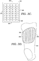
- FIG. 3C a front view of an outward side 301 of a substrate 300 retaining a plurality of protective plates 200 is shown after the plurality of protective plates 200 have been forced downwards from the configuration shown in FIG. 3B . Accordingly, the plurality of protective plates 200 extend downwards at an acute angle relative to the anatomy of the wearer in an as worn position. As can be seen in the example of FIG. 3C , protective plates 200 may be retained by connection points 310 of substrate 300 in a fashion that causes protective plates 200 to overlap along a horizontal direction as well as a vertical direction.
- substrate 300 may have a right edge 305 and a left edge 306 relative to a wearer in an as worn position, with a plurality of protective plates 200 retained by substrate 300 such that at least some of the plurality of protective plates overlap another plate to either the left or right in an as worn position.
- the thickness of different portions of protective plates 200 may be selected such that the overlaps illustrated in FIGS. 3B and 3C do not cause the total thickness of the overlapping protective plates 200 to be uncomfortably thick for the wearer.
- FIG. 3D an example of a plurality of protective plates 200 retained in an overlapping fashion by a substrate 300 is shown in phantom while retained within a pocket of pants 104 suitable for American football. While illustrated in the present example of protecting the thigh 390 of an American football player in an as worn position, protective devices of overlapping protective plates may be used to protect other portions of a wearer's anatomy and/or for protection of athletes engaged in sports other than American football.
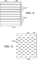
- grooves 410 are substantially straight and substantially parallel with one another and bottom edge 404 of substrate 400, but other orientations are possible.
- grooves 410 may be curvilinear, may be oriented in intersecting lines or curves, may have different spacing between individual grooves 410, etc.
- Grooves 410 may correspond with the thickness of a corresponding connection point of a protective plate (such as one of connection points 202, 204, 206, or 208 of a protective plate 200) in order to form a friction fit to retain a protective plate within groove.
- groove 410 may be slightly smaller than second thickness 282 of a protective plate 200, such that a connection point 202 of the protective plate 200 is slightly compressed upon insertion into groove 410, thereby retaining protective plate in position.
- slots 510 may frictionally retain a protective plate (such as protective plate 200) when the protective plate 200 is inserted into slot 510.
- connection mechanisms beyond the grooves 410 and slots 510 illustrated in the above examples may be used to retain protective plates within a flexible plate. While a friction fit is relatively durable, easy to use, and straight forward to manufacture, other mechanisms such as hook and loop systems, hook and eye systems, snaps, adhesives, welds, and the like may be used as connection points.
- a connection mechanism may be able to be disengaged to permit the disassembly and reconfiguration of protective plates, but a connection mechanism may not be disengagable once engaged in some examples.
- a substrate such as substrate 400 (or other examples of substrates described elsewhere herein) need not be rectangular, and may instead be irregular or have at least a partially curvilinear perimeter.
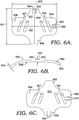
- FIG. 6A illustrates a further example of a protective plate 600 that may be used to form a protective device in accordance with the present invention.
- Protective plate 600 may be formed of a nylon, polypropelene, ABS, rubber, plastic, foam, or other material.
- a protective plate such as protective plate 600 may provide at least one connection point 650 that engages with a connection point on another protective plate, thereby allowing protective plates to be assembled in an overlapping fashion without the use of a substrate to retain the protective plates 600.
- connection point 650 may comprise ridges that extend from the outward face 645 of protective plate 600.
- a protective plate may optionally provide a plurality of ventilation openings 601 that permit air flow through protective plate 600.
- Protective plate may have a height 611 along a first axis 610 and a width 622 along a second axis 620. While the present example protective plate 600 with a top (as worn) extension 602 and a symmetrically corresponding bottom (as worn) extension 606, as well as a right (as worn) extension 604 and a symmetrically corresponding left (as worn) extension 608, a protective plate in accordance with the present invention may have any shape or configuration.
- a first connection point 650 comprising a pair of ridges may be located extending from the outward face 645 and a second connection point 660 may comprise a pair of ridges extending from the outward face 645 on the left extension 604.
- protective plate 600 may have a curvature selected to conform to the portion of the anatomy to be protected.
- the curvature of a protective plate may comprise a simple curve or a complex curve in three dimensions while a curved plate is illustrated in the example of protective plate 600 that does not connect to a substrate, other types of protective plates, such as protective plate 200, may provide a curvature while connecting to a substrate.
- Protective plate 600 may have a thickness 632. Ridges of first connection point 650 and second connection point 660 extend above outward face 645 of protective plate 600.
- slots corresponding to a third connection point 640 and a fourth connection point 670 may not be seen because they extend below inward face 655 of protective plate 600.
- the shape and size of slots of third connection point 640 and fourth connection point 670 may correspond to the ridges of first connection point 650 and second connection point 660 to permit the slots and ridges of different connection points to mate and retain the plates in an overlapping fashion.
- connection point 640 may comprise a pair of slots that extend into inward face 645 on the bottom extension 606 and a fourth connection point 670 may comprise a pair of slots that extend into inward face 645 on a right extension 608.
- connection points used to interconnection protective plates in accordance with the present invention may vary based upon the size and/or shape of the plate, the material used to form the plate, the portion of the wearer's anatomy to be protected by a plurality of protective plates, etc.
- first protective plate 700 connects in an overlapping fashion with a second protective plate 701.
- First protective plate 700 and second protective plate 701 may both resemble the example protective plate 600 described above, but may have different sizes, shapes, and/or configurations than described above, and need not be identical to one another.
- First protective plate 700 may have a first connection point 750 that interconnects with a second connection point 760 on second plate.
- connection point 750 may comprise one or more slot
- connection point 760 may comprise one or more ridge that mates with the one or more slots at connection point 750.
- a first protective plate 801, a second protective plate 802, a third protective plate 803, and a fourth protective plate 804 are shown retained together in an overlapping fashion. Any type of connection points may be used to retain protective plates 801, 802, 803, 804 together. While protective plates 801, 802, 803, 804 are shown in this example as having similar sizes and shapes, protective plates having different sizes and/or shapes may be assembled at connection points in accordance with the present invention. Further, more or fewer protective plates than the four illustrated in the example of FIG 8 may be used in a protective device in accordance with the present invention, and the arrangement and configuration of assembled protective plates may vary from that shown in the example of FIG. 8 .
- assembly 900 of protective plates such as protective plate 600 are shown retained within a pocket of pants 104 suitable for wear while playing American football.
- Assembly 900 may be retained in a pocket of pants 104 to retain assembly over a portion of the anatomy of the wearer, such as thigh 990.
- Each of the plates in assembly 900 extend at an acute angle relative to the thigh 990 of the wearer in the as worn position shown.
- An assembly of overlapping protective plates such as assembly 900 may be used to protect other portions of a wearer's anatomy and may be used to provide protection for sports other than American football.
Landscapes
- Health & Medical Sciences (AREA)
- General Health & Medical Sciences (AREA)
- Physical Education & Sports Medicine (AREA)
- Engineering & Computer Science (AREA)
- Textile Engineering (AREA)
- Professional, Industrial, Or Sporting Protective Garments (AREA)
Claims (7)
- Schutzvorrichtung, die einen Teil der Anatomie des Trägers vor einem Aufprall schützt, wobei die Schutzvorrichtung umfasst:eine Mehrzahl stoßabsorbierender Platten (600, 700, 701), wobei jede der Mehrzahl stoßabsorbierender Platten (600, 700, 701) eine obere Fläche (645) und eine untere Fläche (655) aufweist;eine Mehrzahl von Verbindungspunkten (650, 660, 750) an den oberen Flächen der Mehrzahl stoßabsorbierender Platten; undeine Mehrzahl von Verbindungspunkten (640, 670, 760) an den unteren Flächen der Mehrzahl stoßabsorbierender Platten, wobei jeder der Mehrzahl von Verbindungspunkten an den unteren Flächen der Mehrzahl stoßabsorbierender Platten zur Verbindung mit den Verbindungspunkten an den oberen Flächen der stoßabsorbierenden Platten geeignet ist, wobei die Mehrzahl stoßabsorbierender Platten in teilweise überlappender Weise über den Teil der Anatomie des Trägers gehalten ist, der vor Stößen zu schützen ist, wenn die Verbindungspunkte an den unteren Flächen mit den Verbindungspunkten an den oberen Fläche verbunden sind und die Schutzvorrichtung getragen wird, dadurch gekennzeichnet, dass die Verbindungspunkte (650, 660, 750) an der oberen Fläche (645) einer ersten Platte (600, 700) der Mehrzahl stoßabsorbierender Platten Rippen sind und die Verbindungspunkte (640, 670, 760) an der unteren Fläche (655) einer zweiten Platte (701) der Mehrzahl stoßabsorbierender Platten entsprechende Schlitze sind.
- Schutzvorrichtung nach Anspruch 1, wobei die Platten (600, 700, 701) der Mehrzahl stoßabsorbierender Platten aus einem Nylon gebildet sind.
- Schutzvorrichtung nach Anspruch 1, wobei die Platten (600, 700, 701) der Mehrzahl stoßabsorbierender Platten aus Polypropylen gebildet sind.
- Schutzvorrichtung nach Anspruch 1, wobei die Platten (600, 700, 701) der Mehrzahl stoßabsorbierender Platten aus Acrylnitril-Butadien-Styrol gebildet sind.
- Schutzvorrichtung nach einem der Ansprüche 1 bis 4, wobei eine erste Platte (600, 700) der Mehrzahl stoßabsorbierender Platten einen Satz von zwei oder mehr Rippen (650, 660, 750) an der oberen Fläche (645) enthält, und wobei eine zweite Platte (710) der Mehrzahl stoßabsorbierender Platten einen Satz von zwei oder mehr Schlitzen (640, 670, 760) an der unteren Fläche (655) enthält, die mit dem Satz von zwei oder mehr Rippen zusammenpassen.
- Schutzvorrichtung nach einem der Ansprüche 1 bis 5, wobei die Mehrzahl von Verbindungspunkten (640, 650, 660, 670) ermöglicht, die stoßabsorbierenden Platten (600, 700, 710) in überlappender Weise ohne Verwendung eines Substrats zum Zurückhalten der stoßabsorbierenden Platten zu montieren.
- Schutzvorrichtung nach einem der Ansprüche 1 bis 6, wobei eine stoßabsorbierende Platte (600, 700, 710) eine Mehrzahl von Belüftungsöffnungen (601) enthält.
Applications Claiming Priority (3)
| Application Number | Priority Date | Filing Date | Title |
|---|---|---|---|
| US13/795,547 US9101171B2 (en) | 2013-03-12 | 2013-03-12 | Multi-component impact protection device for athletics |
| PCT/US2014/021312 WO2014164219A1 (en) | 2013-03-12 | 2014-03-06 | Multi-component impact protection device for athletics |
| EP14778879.8A EP2972056B1 (de) | 2013-03-12 | 2014-03-06 | Mehrkomponentige aufprallschutzvorrichtung für sportler |
Related Parent Applications (2)
| Application Number | Title | Priority Date | Filing Date |
|---|---|---|---|
| EP14778879.8A Division EP2972056B1 (de) | 2013-03-12 | 2014-03-06 | Mehrkomponentige aufprallschutzvorrichtung für sportler |
| EP14778879.8A Division-Into EP2972056B1 (de) | 2013-03-12 | 2014-03-06 | Mehrkomponentige aufprallschutzvorrichtung für sportler |
Publications (2)
| Publication Number | Publication Date |
|---|---|
| EP3370031A1 EP3370031A1 (de) | 2018-09-05 |
| EP3370031B1 true EP3370031B1 (de) | 2020-06-03 |
Family
ID=51520426
Family Applications (2)
| Application Number | Title | Priority Date | Filing Date |
|---|---|---|---|
| EP14778879.8A Active EP2972056B1 (de) | 2013-03-12 | 2014-03-06 | Mehrkomponentige aufprallschutzvorrichtung für sportler |
| EP18162759.7A Active EP3370031B1 (de) | 2013-03-12 | 2014-03-06 | Mehrkomponentige aufprallschutzvorrichtung für sportler |
Family Applications Before (1)
| Application Number | Title | Priority Date | Filing Date |
|---|---|---|---|
| EP14778879.8A Active EP2972056B1 (de) | 2013-03-12 | 2014-03-06 | Mehrkomponentige aufprallschutzvorrichtung für sportler |
Country Status (4)
| Country | Link |
|---|---|
| US (1) | US9101171B2 (de) |
| EP (2) | EP2972056B1 (de) |
| CN (1) | CN105026877B (de) |
| WO (1) | WO2014164219A1 (de) |
Families Citing this family (6)
| Publication number | Priority date | Publication date | Assignee | Title |
|---|---|---|---|---|
| US9908027B2 (en) * | 2014-04-22 | 2018-03-06 | Nike, Inc. | Article of apparel with dynamic padding system |
| BR112018005761A2 (pt) * | 2015-09-22 | 2019-01-15 | Univ Akron | dispositivo de proteção contra impactos e absorção de choques |
| GB2546721B (en) * | 2015-11-05 | 2020-08-05 | Nurvv Ltd | A structure to absorb, dissipate and measure a force |
| USD795534S1 (en) * | 2015-11-19 | 2017-08-29 | Nike, Inc. | Pant |
| RU167891U1 (ru) * | 2016-03-16 | 2017-01-11 | Общество с ограниченной ответственностью "РОМБ" (ООО "РОМБ") | Композитная керамическая бронепанель |
| US11019855B2 (en) * | 2017-05-31 | 2021-06-01 | Nike, Inc. | Vortex-generator device |
Family Cites Families (37)
| Publication number | Priority date | Publication date | Assignee | Title |
|---|---|---|---|---|
| US921352A (en) * | 1909-01-09 | 1909-05-11 | George Hazzard Blaker | Protective vest. |
| US1021804A (en) * | 1910-12-12 | 1912-04-02 | Anna Margaretha Schneider | Armor. |
| US1290799A (en) | 1918-02-06 | 1919-01-07 | Edwin R Talley | Life-protecting body-guard. |
| US1282411A (en) * | 1918-07-30 | 1918-10-22 | Stanislaw Golembiowski | Soldier's protector. |
| US1915754A (en) * | 1932-05-26 | 1933-06-27 | Dennis C O'shea | Hip pad |
| US3746605A (en) * | 1971-08-09 | 1973-07-17 | Eastman Kodak Co | Cushioning material |
| US3867239A (en) * | 1973-06-11 | 1975-02-18 | Us Army | Body armor construction |
| US4377009A (en) * | 1979-09-17 | 1983-03-22 | Huey Douglas | Head protector |
| US4322858A (en) * | 1979-09-17 | 1982-04-06 | Douglas Equipment Manufacturing Co. | Protective garments for football players |
| US4483020A (en) * | 1982-11-17 | 1984-11-20 | Jack P. Cittadine | Projectile proof vest |
| NZ204749A (en) * | 1983-03-18 | 1987-08-31 | Moray Ltd | Garment with parts protected by overlapping material sections |
| US4633756A (en) | 1984-05-21 | 1987-01-06 | Rudoi Boris L | Bullet proof armor shield |
| US4648554A (en) * | 1984-10-30 | 1987-03-10 | Acme Plastics, Inc. | Impact and vibration attenuating pad with offset dimples |
| JPH0650240B2 (ja) * | 1985-08-16 | 1994-06-29 | 伊藤忠商事株式会社 | 人体防護材 |
| US4951689A (en) * | 1988-06-17 | 1990-08-28 | Jones J Paul | Armoring system for protective body covers |
| US5906873A (en) * | 1996-07-03 | 1999-05-25 | Higher Dimension Medical, Inc. | Puncture, pierce, and cut resistant fabric |
| IL142986A0 (en) | 1998-11-09 | 2002-04-21 | Pinnacle Armor L L C | Method and apparatus for defeating high-velocity projectiles |
| US6035438A (en) * | 1999-04-30 | 2000-03-14 | Neal; Murray L. | Method and apparatus for defeating ballistic projectiles |
| US6170378B1 (en) * | 1998-11-09 | 2001-01-09 | Murray L. Neal | Method and apparatus for defeating high-velocity projectiles |
| US6510777B2 (en) * | 1999-04-30 | 2003-01-28 | Pinnacle Armor, Llc | Encapsulated imbricated armor system |
| WO2001087102A1 (en) * | 2000-05-19 | 2001-11-22 | Armadillo Sports Design Limited | A protective article of footwear |
| US6715218B2 (en) | 2002-02-12 | 2004-04-06 | Adidas International B.V. | Unidirectional support device |
| US6953111B2 (en) * | 2002-03-22 | 2005-10-11 | Yoshida Sports, Inc. | Protective structure for a travel case |
| US7490358B1 (en) * | 2004-08-13 | 2009-02-17 | Diamondback Tactical L.L.L.P. | Back armor |
| US7082621B1 (en) * | 2005-09-09 | 2006-08-01 | Fratesi Gary R | Thigh pad protectors |
| US20070234458A1 (en) | 2005-09-15 | 2007-10-11 | Federal Covers & Textiles, Inc. | Composite segmented flexible armor |
| US8336117B2 (en) * | 2005-10-19 | 2012-12-25 | Nike, Inc. | Article of apparel with material elements having a reversible structure |
| US7500422B2 (en) * | 2005-12-16 | 2009-03-10 | Robert Mazur | Modular functional star-disc system |
| US20070141969A1 (en) | 2005-12-21 | 2007-06-21 | Cybulski Eric R | Sanding tool with molding interface pad |
| WO2008146289A2 (en) | 2007-05-29 | 2008-12-04 | Celine Tezartes-Strauss | Garment with built-in protecting pads |
| US8434396B1 (en) * | 2007-07-23 | 2013-05-07 | Verco Materials, Llc | Armor arrangement |
| US20090255022A1 (en) | 2008-04-14 | 2009-10-15 | Smith Barry L | Molded Torso-conforming body armor including method of producing same |
| US8245842B2 (en) | 2008-06-27 | 2012-08-21 | Switcheasy Limited | Protective case having a hybrid structure for portable handheld electronic devices |
| US8438669B2 (en) * | 2009-06-23 | 2013-05-14 | Nike, Inc. | Apparel incorporating a protective element |
| US8438667B2 (en) * | 2009-09-24 | 2013-05-14 | Nike, Inc. | Apparel incorporating a protective element |
| US8702895B2 (en) * | 2010-04-07 | 2014-04-22 | Nike, Inc. | Cushioning elements for apparel and other products and methods of manufacturing the cushioning elements |
| EP2563173B8 (de) * | 2010-04-29 | 2014-08-27 | Morton Breindahl Holding ApS | Thermische abschirmung für ein neugeborenes |
-
2013
- 2013-03-12 US US13/795,547 patent/US9101171B2/en active Active
-
2014
- 2014-03-06 EP EP14778879.8A patent/EP2972056B1/de active Active
- 2014-03-06 CN CN201480013068.1A patent/CN105026877B/zh active Active
- 2014-03-06 EP EP18162759.7A patent/EP3370031B1/de active Active
- 2014-03-06 WO PCT/US2014/021312 patent/WO2014164219A1/en not_active Ceased
Non-Patent Citations (1)
| Title |
|---|
| None * |
Also Published As
| Publication number | Publication date |
|---|---|
| EP3370031A1 (de) | 2018-09-05 |
| EP2972056A1 (de) | 2016-01-20 |
| US20140259323A1 (en) | 2014-09-18 |
| EP2972056B1 (de) | 2018-04-25 |
| EP2972056A4 (de) | 2016-08-31 |
| CN105026877A (zh) | 2015-11-04 |
| WO2014164219A1 (en) | 2014-10-09 |
| CN105026877B (zh) | 2017-03-15 |
| US9101171B2 (en) | 2015-08-11 |
Similar Documents
| Publication | Publication Date | Title |
|---|---|---|
| EP2967170B1 (de) | Mehrmaterial-aufprallschutz für kontaktsportarten | |
| EP3370031B1 (de) | Mehrkomponentige aufprallschutzvorrichtung für sportler | |
| US10687566B2 (en) | Modular impact protection system for athletic wear | |
| EP2967164B1 (de) | Ineinandergreifendes aufprallschutzsystem für kontaktsportarten | |
| US10555566B2 (en) | Impact protection systems | |
| US5245706A (en) | Chest protector | |
| US20180000185A1 (en) | Protective Headgear | |
| US10194707B2 (en) | Apparel incorporating a protective element | |
| US20150101110A1 (en) | Protective padding assembly for a sports apparel article | |
| US10695650B2 (en) | Protective apparatus with grooves | |
| US11684095B2 (en) | Modular disengaging system | |
| US20170217126A1 (en) | Foam structure and protective pad having same | |
| US9649548B2 (en) | Protective element for use in sport | |
| US7877820B2 (en) | Artificial disc | |
| US7721348B2 (en) | Protective element | |
| EP3439756B1 (de) | Stossdämpfende teilschicht für einen schulterpolster | |
| US20250241385A1 (en) | Apparatuses, systems and methods for equipment for protecting the human body by absorbing and dissipating forces imparted to the body | |
| CN100534555C (zh) | 保护部件 | |
| JP4672051B2 (ja) | 球技用レッグガード | |
| CA2969799A1 (en) | Protective headgear | |
| TWM541879U (zh) | 護脛結構 |
Legal Events
| Date | Code | Title | Description |
|---|---|---|---|
| PUAI | Public reference made under article 153(3) epc to a published international application that has entered the european phase |
Free format text: ORIGINAL CODE: 0009012 |
|
| STAA | Information on the status of an ep patent application or granted ep patent |
Free format text: STATUS: THE APPLICATION HAS BEEN PUBLISHED |
|
| AC | Divisional application: reference to earlier application |
Ref document number: 2972056 Country of ref document: EP Kind code of ref document: P |
|
| AK | Designated contracting states |
Kind code of ref document: A1 Designated state(s): AL AT BE BG CH CY CZ DE DK EE ES FI FR GB GR HR HU IE IS IT LI LT LU LV MC MK MT NL NO PL PT RO RS SE SI SK SM TR |
|
| STAA | Information on the status of an ep patent application or granted ep patent |
Free format text: STATUS: REQUEST FOR EXAMINATION WAS MADE |
|
| 17P | Request for examination filed |
Effective date: 20190213 |
|
| RBV | Designated contracting states (corrected) |
Designated state(s): AL AT BE BG CH CY CZ DE DK EE ES FI FR GB GR HR HU IE IS IT LI LT LU LV MC MK MT NL NO PL PT RO RS SE SI SK SM TR |
|
| STAA | Information on the status of an ep patent application or granted ep patent |
Free format text: STATUS: EXAMINATION IS IN PROGRESS |
|
| 17Q | First examination report despatched |
Effective date: 20190423 |
|
| GRAP | Despatch of communication of intention to grant a patent |
Free format text: ORIGINAL CODE: EPIDOSNIGR1 |
|
| STAA | Information on the status of an ep patent application or granted ep patent |
Free format text: STATUS: GRANT OF PATENT IS INTENDED |
|
| INTG | Intention to grant announced |
Effective date: 20200108 |
|
| GRAS | Grant fee paid |
Free format text: ORIGINAL CODE: EPIDOSNIGR3 |
|
| GRAA | (expected) grant |
Free format text: ORIGINAL CODE: 0009210 |
|
| STAA | Information on the status of an ep patent application or granted ep patent |
Free format text: STATUS: THE PATENT HAS BEEN GRANTED |
|
| AC | Divisional application: reference to earlier application |
Ref document number: 2972056 Country of ref document: EP Kind code of ref document: P |
|
| AK | Designated contracting states |
Kind code of ref document: B1 Designated state(s): AL AT BE BG CH CY CZ DE DK EE ES FI FR GB GR HR HU IE IS IT LI LT LU LV MC MK MT NL NO PL PT RO RS SE SI SK SM TR |
|
| REG | Reference to a national code |
Ref country code: GB Ref legal event code: FG4D |
|
| REG | Reference to a national code |
Ref country code: CH Ref legal event code: EP Ref country code: AT Ref legal event code: REF Ref document number: 1277439 Country of ref document: AT Kind code of ref document: T Effective date: 20200615 |
|
| REG | Reference to a national code |
Ref country code: DE Ref legal event code: R096 Ref document number: 602014066400 Country of ref document: DE |
|
| REG | Reference to a national code |
Ref country code: LT Ref legal event code: MG4D |
|
| PG25 | Lapsed in a contracting state [announced via postgrant information from national office to epo] |
Ref country code: NO Free format text: LAPSE BECAUSE OF FAILURE TO SUBMIT A TRANSLATION OF THE DESCRIPTION OR TO PAY THE FEE WITHIN THE PRESCRIBED TIME-LIMIT Effective date: 20200903 Ref country code: GR Free format text: LAPSE BECAUSE OF FAILURE TO SUBMIT A TRANSLATION OF THE DESCRIPTION OR TO PAY THE FEE WITHIN THE PRESCRIBED TIME-LIMIT Effective date: 20200904 Ref country code: FI Free format text: LAPSE BECAUSE OF FAILURE TO SUBMIT A TRANSLATION OF THE DESCRIPTION OR TO PAY THE FEE WITHIN THE PRESCRIBED TIME-LIMIT Effective date: 20200603 Ref country code: LT Free format text: LAPSE BECAUSE OF FAILURE TO SUBMIT A TRANSLATION OF THE DESCRIPTION OR TO PAY THE FEE WITHIN THE PRESCRIBED TIME-LIMIT Effective date: 20200603 Ref country code: SE Free format text: LAPSE BECAUSE OF FAILURE TO SUBMIT A TRANSLATION OF THE DESCRIPTION OR TO PAY THE FEE WITHIN THE PRESCRIBED TIME-LIMIT Effective date: 20200603 |
|
| REG | Reference to a national code |
Ref country code: NL Ref legal event code: MP Effective date: 20200603 |
|
| PG25 | Lapsed in a contracting state [announced via postgrant information from national office to epo] |
Ref country code: HR Free format text: LAPSE BECAUSE OF FAILURE TO SUBMIT A TRANSLATION OF THE DESCRIPTION OR TO PAY THE FEE WITHIN THE PRESCRIBED TIME-LIMIT Effective date: 20200603 Ref country code: RS Free format text: LAPSE BECAUSE OF FAILURE TO SUBMIT A TRANSLATION OF THE DESCRIPTION OR TO PAY THE FEE WITHIN THE PRESCRIBED TIME-LIMIT Effective date: 20200603 Ref country code: BG Free format text: LAPSE BECAUSE OF FAILURE TO SUBMIT A TRANSLATION OF THE DESCRIPTION OR TO PAY THE FEE WITHIN THE PRESCRIBED TIME-LIMIT Effective date: 20200903 Ref country code: LV Free format text: LAPSE BECAUSE OF FAILURE TO SUBMIT A TRANSLATION OF THE DESCRIPTION OR TO PAY THE FEE WITHIN THE PRESCRIBED TIME-LIMIT Effective date: 20200603 |
|
| REG | Reference to a national code |
Ref country code: AT Ref legal event code: MK05 Ref document number: 1277439 Country of ref document: AT Kind code of ref document: T Effective date: 20200603 |
|
| PG25 | Lapsed in a contracting state [announced via postgrant information from national office to epo] |
Ref country code: AL Free format text: LAPSE BECAUSE OF FAILURE TO SUBMIT A TRANSLATION OF THE DESCRIPTION OR TO PAY THE FEE WITHIN THE PRESCRIBED TIME-LIMIT Effective date: 20200603 Ref country code: NL Free format text: LAPSE BECAUSE OF FAILURE TO SUBMIT A TRANSLATION OF THE DESCRIPTION OR TO PAY THE FEE WITHIN THE PRESCRIBED TIME-LIMIT Effective date: 20200603 |
|
| PG25 | Lapsed in a contracting state [announced via postgrant information from national office to epo] |
Ref country code: ES Free format text: LAPSE BECAUSE OF FAILURE TO SUBMIT A TRANSLATION OF THE DESCRIPTION OR TO PAY THE FEE WITHIN THE PRESCRIBED TIME-LIMIT Effective date: 20200603 Ref country code: AT Free format text: LAPSE BECAUSE OF FAILURE TO SUBMIT A TRANSLATION OF THE DESCRIPTION OR TO PAY THE FEE WITHIN THE PRESCRIBED TIME-LIMIT Effective date: 20200603 Ref country code: CZ Free format text: LAPSE BECAUSE OF FAILURE TO SUBMIT A TRANSLATION OF THE DESCRIPTION OR TO PAY THE FEE WITHIN THE PRESCRIBED TIME-LIMIT Effective date: 20200603 Ref country code: RO Free format text: LAPSE BECAUSE OF FAILURE TO SUBMIT A TRANSLATION OF THE DESCRIPTION OR TO PAY THE FEE WITHIN THE PRESCRIBED TIME-LIMIT Effective date: 20200603 Ref country code: SM Free format text: LAPSE BECAUSE OF FAILURE TO SUBMIT A TRANSLATION OF THE DESCRIPTION OR TO PAY THE FEE WITHIN THE PRESCRIBED TIME-LIMIT Effective date: 20200603 Ref country code: IT Free format text: LAPSE BECAUSE OF FAILURE TO SUBMIT A TRANSLATION OF THE DESCRIPTION OR TO PAY THE FEE WITHIN THE PRESCRIBED TIME-LIMIT Effective date: 20200603 Ref country code: EE Free format text: LAPSE BECAUSE OF FAILURE TO SUBMIT A TRANSLATION OF THE DESCRIPTION OR TO PAY THE FEE WITHIN THE PRESCRIBED TIME-LIMIT Effective date: 20200603 Ref country code: PT Free format text: LAPSE BECAUSE OF FAILURE TO SUBMIT A TRANSLATION OF THE DESCRIPTION OR TO PAY THE FEE WITHIN THE PRESCRIBED TIME-LIMIT Effective date: 20201006 |
|
| PG25 | Lapsed in a contracting state [announced via postgrant information from national office to epo] |
Ref country code: SK Free format text: LAPSE BECAUSE OF FAILURE TO SUBMIT A TRANSLATION OF THE DESCRIPTION OR TO PAY THE FEE WITHIN THE PRESCRIBED TIME-LIMIT Effective date: 20200603 Ref country code: PL Free format text: LAPSE BECAUSE OF FAILURE TO SUBMIT A TRANSLATION OF THE DESCRIPTION OR TO PAY THE FEE WITHIN THE PRESCRIBED TIME-LIMIT Effective date: 20200603 Ref country code: IS Free format text: LAPSE BECAUSE OF FAILURE TO SUBMIT A TRANSLATION OF THE DESCRIPTION OR TO PAY THE FEE WITHIN THE PRESCRIBED TIME-LIMIT Effective date: 20201003 |
|
| REG | Reference to a national code |
Ref country code: DE Ref legal event code: R097 Ref document number: 602014066400 Country of ref document: DE |
|
| PLBE | No opposition filed within time limit |
Free format text: ORIGINAL CODE: 0009261 |
|
| STAA | Information on the status of an ep patent application or granted ep patent |
Free format text: STATUS: NO OPPOSITION FILED WITHIN TIME LIMIT |
|
| PG25 | Lapsed in a contracting state [announced via postgrant information from national office to epo] |
Ref country code: DK Free format text: LAPSE BECAUSE OF FAILURE TO SUBMIT A TRANSLATION OF THE DESCRIPTION OR TO PAY THE FEE WITHIN THE PRESCRIBED TIME-LIMIT Effective date: 20200603 |
|
| 26N | No opposition filed |
Effective date: 20210304 |
|
| PG25 | Lapsed in a contracting state [announced via postgrant information from national office to epo] |
Ref country code: SI Free format text: LAPSE BECAUSE OF FAILURE TO SUBMIT A TRANSLATION OF THE DESCRIPTION OR TO PAY THE FEE WITHIN THE PRESCRIBED TIME-LIMIT Effective date: 20200603 |
|
| PG25 | Lapsed in a contracting state [announced via postgrant information from national office to epo] |
Ref country code: MC Free format text: LAPSE BECAUSE OF FAILURE TO SUBMIT A TRANSLATION OF THE DESCRIPTION OR TO PAY THE FEE WITHIN THE PRESCRIBED TIME-LIMIT Effective date: 20200603 |
|
| REG | Reference to a national code |
Ref country code: CH Ref legal event code: PL |
|
| REG | Reference to a national code |
Ref country code: BE Ref legal event code: MM Effective date: 20210331 |
|
| PG25 | Lapsed in a contracting state [announced via postgrant information from national office to epo] |
Ref country code: CH Free format text: LAPSE BECAUSE OF NON-PAYMENT OF DUE FEES Effective date: 20210331 Ref country code: IE Free format text: LAPSE BECAUSE OF NON-PAYMENT OF DUE FEES Effective date: 20210306 Ref country code: LU Free format text: LAPSE BECAUSE OF NON-PAYMENT OF DUE FEES Effective date: 20210306 Ref country code: LI Free format text: LAPSE BECAUSE OF NON-PAYMENT OF DUE FEES Effective date: 20210331 |
|
| PG25 | Lapsed in a contracting state [announced via postgrant information from national office to epo] |
Ref country code: BE Free format text: LAPSE BECAUSE OF NON-PAYMENT OF DUE FEES Effective date: 20210331 |
|
| P01 | Opt-out of the competence of the unified patent court (upc) registered |
Effective date: 20230515 |
|
| PG25 | Lapsed in a contracting state [announced via postgrant information from national office to epo] |
Ref country code: CY Free format text: LAPSE BECAUSE OF FAILURE TO SUBMIT A TRANSLATION OF THE DESCRIPTION OR TO PAY THE FEE WITHIN THE PRESCRIBED TIME-LIMIT Effective date: 20200603 |
|
| PG25 | Lapsed in a contracting state [announced via postgrant information from national office to epo] |
Ref country code: HU Free format text: LAPSE BECAUSE OF FAILURE TO SUBMIT A TRANSLATION OF THE DESCRIPTION OR TO PAY THE FEE WITHIN THE PRESCRIBED TIME-LIMIT; INVALID AB INITIO Effective date: 20140306 |
|
| PG25 | Lapsed in a contracting state [announced via postgrant information from national office to epo] |
Ref country code: MK Free format text: LAPSE BECAUSE OF FAILURE TO SUBMIT A TRANSLATION OF THE DESCRIPTION OR TO PAY THE FEE WITHIN THE PRESCRIBED TIME-LIMIT Effective date: 20200603 |
|
| PG25 | Lapsed in a contracting state [announced via postgrant information from national office to epo] |
Ref country code: TR Free format text: LAPSE BECAUSE OF FAILURE TO SUBMIT A TRANSLATION OF THE DESCRIPTION OR TO PAY THE FEE WITHIN THE PRESCRIBED TIME-LIMIT Effective date: 20200603 |
|
| PG25 | Lapsed in a contracting state [announced via postgrant information from national office to epo] |
Ref country code: MT Free format text: LAPSE BECAUSE OF FAILURE TO SUBMIT A TRANSLATION OF THE DESCRIPTION OR TO PAY THE FEE WITHIN THE PRESCRIBED TIME-LIMIT Effective date: 20200603 |
|
| PGFP | Annual fee paid to national office [announced via postgrant information from national office to epo] |
Ref country code: FR Payment date: 20251231 Year of fee payment: 13 |
|
| PGFP | Annual fee paid to national office [announced via postgrant information from national office to epo] |
Ref country code: GB Payment date: 20260106 Year of fee payment: 13 |
|
| PGFP | Annual fee paid to national office [announced via postgrant information from national office to epo] |
Ref country code: DE Payment date: 20260102 Year of fee payment: 13 |