EP2967857B1 - Dispositifs pour traiter la régurgitation valvulaire tricuspide fonctionnelle - Google Patents
Dispositifs pour traiter la régurgitation valvulaire tricuspide fonctionnelle Download PDFInfo
- Publication number
- EP2967857B1 EP2967857B1 EP14723540.2A EP14723540A EP2967857B1 EP 2967857 B1 EP2967857 B1 EP 2967857B1 EP 14723540 A EP14723540 A EP 14723540A EP 2967857 B1 EP2967857 B1 EP 2967857B1
- Authority
- EP
- European Patent Office
- Prior art keywords
- compression member
- tensioning element
- heart
- compression
- catheter
- Prior art date
- Legal status (The legal status is an assumption and is not a legal conclusion. Google has not performed a legal analysis and makes no representation as to the accuracy of the status listed.)
- Active
Links
Images




Classifications
-
- A—HUMAN NECESSITIES
- A61—MEDICAL OR VETERINARY SCIENCE; HYGIENE
- A61F—FILTERS IMPLANTABLE INTO BLOOD VESSELS; PROSTHESES; DEVICES PROVIDING PATENCY TO, OR PREVENTING COLLAPSING OF, TUBULAR STRUCTURES OF THE BODY, e.g. STENTS; ORTHOPAEDIC, NURSING OR CONTRACEPTIVE DEVICES; FOMENTATION; TREATMENT OR PROTECTION OF EYES OR EARS; BANDAGES, DRESSINGS OR ABSORBENT PADS; FIRST-AID KITS
- A61F2/00—Filters implantable into blood vessels; Prostheses, i.e. artificial substitutes or replacements for parts of the body; Appliances for connecting them with the body; Devices providing patency to, or preventing collapsing of, tubular structures of the body, e.g. stents
- A61F2/02—Prostheses implantable into the body
- A61F2/24—Heart valves ; Vascular valves, e.g. venous valves; Heart implants, e.g. passive devices for improving the function of the native valve or the heart muscle; Transmyocardial revascularisation [TMR] devices; Valves implantable in the body
- A61F2/2478—Passive devices for improving the function of the heart muscle, i.e. devices for reshaping the external surface of the heart, e.g. bags, strips or bands
- A61F2/2481—Devices outside the heart wall, e.g. bags, strips or bands
-
- A—HUMAN NECESSITIES
- A61—MEDICAL OR VETERINARY SCIENCE; HYGIENE
- A61F—FILTERS IMPLANTABLE INTO BLOOD VESSELS; PROSTHESES; DEVICES PROVIDING PATENCY TO, OR PREVENTING COLLAPSING OF, TUBULAR STRUCTURES OF THE BODY, e.g. STENTS; ORTHOPAEDIC, NURSING OR CONTRACEPTIVE DEVICES; FOMENTATION; TREATMENT OR PROTECTION OF EYES OR EARS; BANDAGES, DRESSINGS OR ABSORBENT PADS; FIRST-AID KITS
- A61F2/00—Filters implantable into blood vessels; Prostheses, i.e. artificial substitutes or replacements for parts of the body; Appliances for connecting them with the body; Devices providing patency to, or preventing collapsing of, tubular structures of the body, e.g. stents
- A61F2/02—Prostheses implantable into the body
- A61F2/24—Heart valves ; Vascular valves, e.g. venous valves; Heart implants, e.g. passive devices for improving the function of the native valve or the heart muscle; Transmyocardial revascularisation [TMR] devices; Valves implantable in the body
- A61F2/2442—Annuloplasty rings or inserts for correcting the valve shape; Implants for improving the function of a native heart valve
-
- A—HUMAN NECESSITIES
- A61—MEDICAL OR VETERINARY SCIENCE; HYGIENE
- A61F—FILTERS IMPLANTABLE INTO BLOOD VESSELS; PROSTHESES; DEVICES PROVIDING PATENCY TO, OR PREVENTING COLLAPSING OF, TUBULAR STRUCTURES OF THE BODY, e.g. STENTS; ORTHOPAEDIC, NURSING OR CONTRACEPTIVE DEVICES; FOMENTATION; TREATMENT OR PROTECTION OF EYES OR EARS; BANDAGES, DRESSINGS OR ABSORBENT PADS; FIRST-AID KITS
- A61F2/00—Filters implantable into blood vessels; Prostheses, i.e. artificial substitutes or replacements for parts of the body; Appliances for connecting them with the body; Devices providing patency to, or preventing collapsing of, tubular structures of the body, e.g. stents
- A61F2/02—Prostheses implantable into the body
- A61F2/24—Heart valves ; Vascular valves, e.g. venous valves; Heart implants, e.g. passive devices for improving the function of the native valve or the heart muscle; Transmyocardial revascularisation [TMR] devices; Valves implantable in the body
- A61F2/2478—Passive devices for improving the function of the heart muscle, i.e. devices for reshaping the external surface of the heart, e.g. bags, strips or bands
- A61F2/2481—Devices outside the heart wall, e.g. bags, strips or bands
- A61F2002/2484—Delivery devices therefor
-
- A—HUMAN NECESSITIES
- A61—MEDICAL OR VETERINARY SCIENCE; HYGIENE
- A61F—FILTERS IMPLANTABLE INTO BLOOD VESSELS; PROSTHESES; DEVICES PROVIDING PATENCY TO, OR PREVENTING COLLAPSING OF, TUBULAR STRUCTURES OF THE BODY, e.g. STENTS; ORTHOPAEDIC, NURSING OR CONTRACEPTIVE DEVICES; FOMENTATION; TREATMENT OR PROTECTION OF EYES OR EARS; BANDAGES, DRESSINGS OR ABSORBENT PADS; FIRST-AID KITS
- A61F2220/00—Fixations or connections for prostheses classified in groups A61F2/00 - A61F2/26 or A61F2/82 or A61F9/00 or A61F11/00 or subgroups thereof
- A61F2220/0008—Fixation appliances for connecting prostheses to the body
- A61F2220/0016—Fixation appliances for connecting prostheses to the body with sharp anchoring protrusions, e.g. barbs, pins, spikes
Definitions
- This application is related to devices for treating tricuspid valve regurgitation, including devices for tricuspid valve annuloplasty.
- Tricuspid valve regurgitation is a condition in which one of the valves of the heart "leaks" causing right ventricular blood to flow backwards into the right atrium. Commonly this occurs because the tricuspid valve annulus dilates beyond its ideal size. Addressing the condition is difficult because surgical tricuspid valve replacement is invasive and associated with significant morbidity and even mortality. Moreover, prosthetic tricuspid valves are prone to serious complications including thrombosis and infection, which makes the valve replacement approach less desirable.
- US 2006/247491 A1 discloses devices and methods for improving the function of a valve (e.g., mitral valve) by positioning an implantable device outside and adjacent the heart wall such that the device alters the shape of the heart wall acting on the valve.
- a valve e.g., mitral valve
- WO 2012/043898 A1 discloses devices for the treatment of mitral leaflet circulation used in a mitral valve circlag procedures performed in patients with mitral regurgitation.
- Described below are new approaches to treating functional tricuspid valve regurgitation that address some of the limitations and risks of conventional approaches.
- a device for tricuspid valve annuloplasty or other procedure in the area of the heart's atrioventricular groove comprises a tensioning element and a compression member.
- the tensioning element is configured to be delivered by a flexible member guided through a catheter and positioned along or near the heart's atrioventricular groove.
- the compression member is positionable along the tensioning element and over a desired segment of the atrioventricular groove to develop force to be applied to an adjacent area of the heart by selective tensioning of the tensioning element.
- the device can be deliverable through a catheter via the vasculature through the right atrium or right atrial appendage, or inserted along a trans-thoracic or subxiphoid or subcostal path.
- the compression member can be positionable along the tensioning element by using a capture device securable to the compression device to move the compression device relative to the tensioning element.
- the compression member can be tubular and define a bore dimensioned to allow the tensioning element to pass through the compression member.
- the compression member has a groove dimensioned to receive the tensioning element and to assist in retaining contact between the tensioning element and the compression member.
- the compression member can have at least one anti-slip feature configured to contact a surface to reduce slipping of the compression member relative to the heart when the compression member is in position over the desired segment with tension applied to the tensioning element.
- the anti-slip feature can comprise protruding barbs configured to an exterior surface of the heart.
- the compression member has a shaped profile along its length.
- the shaped profile comprises at least two bends and an M-shaped portion.
- the compression member has a generally curved center segment, a generally straight center segment or a center segment having a vertex.
- the compression member has end segments shaped to orient the compression member.
- the compression member is self-orienting upon application of tension in a selected location for treatment.
- the compression element can be shaped such that the compression element is urged into a position normal to the treatment location as tension applied through the tensioning element is increased.
- the compression member can be comprised of multiple component parts separately deliverable through the catheter and configured to be assembled together near a treatment site.
- the compression member can be resiliently deformable such that the compression member changes from a delivery shape suitable for delivery to a final shape after delivery to a treatment site is complete.
- the compression member can be at least partially defined by a first major radius of curvature and a second minor radius of curvature.
- the device can comprise a protection member shaped to provide a protected space at least partially accommodating a blood vessel or other vital structure and to receive the tensioning element, wherein the protection member distributes force developed through increased tension in the tensioning element to either side of the protected space.
- the protection member can be configured for positioning over a coronary artery, or over a pulmonary artery trunk.
- a method of using the device for tricuspid annuloplasty comprises positioning the tensioning element around the heart and generally along the heart's atrioventricular groove, positioning the compression member along the tensioning element an opposite a desired treatment location and applying force to the desired treatment location with the compression element by applying tension with the tensioning.
- Imaging guidance can be used to ascertain positions of at least one of the catheter, the compression member, and the tensioning element.
- the method can comprise positioning at least one compression member along the tensioning element along a desired segment of the atrioventricular groove, the compression member applying force to a desired area of the heart with increasing tension in the tensioning element.
- the method can comprise delivering the compression member through the catheter and through an opening in the right atrial appendage.
- the method can comprise delivering multiple compression member components to the treatment area and assembling the compression member components into the compression member.
- the method can comprise delivering the compression member through the catheter and through the right atrium or an opening in the right atrial appendage.
- the method can comprise positioning at least one protection member along a segment of the tensioning element, the at least one protection member being shaped to provide a protected space at least partially accommodating a blood vessel or other vital structure.
- a “device for tricuspid valve annuloplasty” refers to a device that induces reshaping of an annulus of the heart's tricuspid valve to repair valvular insufficiency.
- Such devices include those that are placed in contact with the annulus of the tricuspid valve, and include those that exert their action by compressive forces on the annulus, such as by placing a flexible annuloplasty member under tension, as in cerclage annuloplasty.
- flexible member refers to an element that is sufficiently flexible to be introduced into the body, generally through a catheter, and manipulated along a desired path within the body, such as in and around the patient's heart.
- a flexible member is a "guide wire" of a conventional catheter, which can refer to a simple guide wire, a stiffened guide wire, or a steerable guide wire that is capable of puncturing and/or penetrating tissue, such as the right atrial appendage.
- the guide wire also can deliver energy to augment its ability to penetrate tissue, for example by puncturing it, delivering radiofrequency ablative energy or by delivering laser ablative energy.
- the guide wire is used to position a separate "tensioning element" made of a suitable tensioning material generally along the heart's atrioventricular groove.
- a tensioning element is usually designed to remain deployed for the duration of the treatment.
- the tensioning element can be formed of any suitable tensioning material, including suture or ligature material or wire.
- the tensioning element may be comprised of segments made of different materials or having different properties, such as different elasticities.
- the guide wire can also serve as the tensioning element.
- a “capture device” is any suitable element or device that can be controlled, usually from outside the body, to engage the tensioning element (usually at a predetermined location along its length) to move and guide the tensioning element to a desired position and/or to manipulate it to increase its tension and the forces applied by it.
- a capture device can be a conventional capture loop or a device having opposing members (like miniature forceps) that can pinch and hold the tensioning element.
- compression member refers to an element that is designed to cooperate with the tensioning element to apply a desired force to an area along the path of the tensioning element.
- the compression member may be designed to provide a greater force to the area than would be applied by the tensioning element alone.
- protection member refers to an element that is designed to cooperate with the tensioning element to provide a protected space to a blood vessel or other vital structure along the path of the tensioning element.
- the protection member is designed so that the blood vessel or vital structure within the protection member experiences less force from the tensioning element than is exerted at adjacent areas at either end of the protection member.
- a flexible member is placed around the annulus of the tricuspid valve, circumferential tension is developed in the flexible member or a tensioning element and resulting force is selectively applied around the tricuspid valve annulus.
- Examples of approaches to cerclage annuloplasty for a mitral valve are disclosed in U.S. Patent No. 8,211,171 .
- the described approaches include a cerclage trajectory through a proximal coronary septal perforator vein and myocardium or annulus fibrosis interposing between that vein and the right ventricle or right atrium to create circumferential cerclage annuloplasty tension.
- the compression and protection members disclosed herein can be made of an "MRI-compatible" material. Such materials are safe to use in the body during magnetic resonance imaging of the body, and do not substantially affect imaging quality of the MRI.
- An "MRI-safe" material is one that does not add substantial risk to a human or equipment by placing it in the magnetic field of an MR environment.
- MRI-compatible materials are non-ferrous materials, such as ceramics, plastics and non-magnetic composite materials.
- Austenitic stainless steels (of the 300 series) are neither ferromagnetic nor paramagnetic and therefore are MRI-compatible. Titanium and aluminum are MRI-compatible, even though they are not ideally paramagnetic.
- Particularly disclosed MRI-compatible materials of which the protective device may be made include nitinol, MP35N and cobalt-chromium alloys.
- tricuspid valve annuloplasty or repair of the tricuspid valve, can be achieved by restricting dilation of the valve's free wall, which enhances coaptation or apposition of the tricuspid valve leaflets.
- functional tricuspid valve regurgitation is treated by selectively introducing circumferential tension around the valve annulus to retard dilation.
- One goal is to augment the effective (forward) right ventricular stroke volume by reducing regurgitant (backward) right ventricular stroke volume.
- the septal-lateral dimension of the tricuspid valve annulus is reduced by extracardiac force or pressure applied through a tensioning element (such as, e.g., a suture) usually in combination with a separate compression member.
- the tensioning element is positioned generally along the atrioventricular groove and tightened to increase force exerted through the compression member on a desired treatment area.
- the compression member is used in conjunction with the tensioning element to enhance the force applied at one or more selected areas.
- the compression member may be designed to preferentially deform as tension is increased in the tensioning element.
- a protection member may be introduced to protect certain vital structures, e.g., blood vessels, within the tensioning element from being deformed by the forces applied by the tensioning element.
- vital structures e.g., blood vessels
- the functions of compression members and protection members may be combined in some applications.
- Fig. 1 is an anatomical schematic cross section of the heart viewed from above. As shown in Fig. 1 and described above, functional tricuspid valve regurgitation or "leakage" results when the free wall of the tricuspid valve dilates. Tricuspid valve annuloplasty, or repair of the heart valve, can be achieved by restricting the dilation of the free wall, which enhances coaptation of the tricuspid valve leaflets.
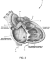
- Fig. 2 depicts a catheter 12 that has been inserted from the femoral vein and directed to penetrate the right atrial appendage to exit the right atrial cavity and enter the pericardial or extracardiac space.
- a flexible member 16 sometimes referred to as a wire, is inserted through a sheath of the catheter, and is shown extending beyond a tip 14 of the catheter.
- a distal end 18 of the flexible member 16, which is the free end, is directed around the heart, such as in the "clockwise" direction as shown by the arrows.
- the path of the flexible member 16 as shown in Fig. 2 is generally along or near the atrioventricular groove on the exterior of the heart.
- a capture loop 20 is provided, such as attached to the flexible member 16 and spaced from its distal end 18.
- the capture loop 20 can be provided on a dedicated flexible member that is separate from the flexible member 16.
- the distal end 18 of the flexible member 16 can be routed around the heart and through the capture loop 20. Thereafter, the flexible member 16 can be withdrawn with the distal end 18 engaged with the capture loop 20 into and back through the catheter, as shown in Fig. 3B .
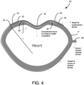
- the flexible member 16 can be replaced with a tensioning element 17 (see, e.g., Fig. 4 ), by attaching the tensioning element 17 to the flexible member 16 with the tensioning member 17 being pulled into place as the flexible member 16 is withdrawn. Tension is then increased in the tensioning member 17.
- a suitable capture device (the capture loop 20 being just one example) can be used to grasp the tensioning element 17 and to manipulate it as desired to effect the required tension.
- this approach can be described as providing extracardiac circumferential tension by a member or device delivered via a transatrial intrapericardial catheter.
- Fig. 4 is a schematic view of a cross-section of the heart showing the location of the tensioning element 17 having been "pulled” into the location previously occupied by the flexible member 16, which has been withdrawn. As also shown in Fig. 4 , there can be a knot or a locking mechanism, such as the lock 46 on the flexible member 16, set to “lock” or fix the tensioning element 17 in place once it has been cinched to a desired degree to provide the predetermined force.
- a knot or a locking mechanism such as the lock 46 on the flexible member 16 set to “lock” or fix the tensioning element 17 in place once it has been cinched to a desired degree to provide the predetermined force.
- a compression member 30 designed to work in conjunction with the tensioning element 17 is shown.
- the compression member 30 is positioned between the heart and the tensioning element 17 such that it bears against the compression member 30 when it is tightened around the heart.
- the tensioning element 17 alone or the flexible member 16 alone, as in some embodiments
- the pressure exerted on the heart is fairly uniform throughout the closed loop encircling the heart.
- the compression member 30, however, is designed to cause greater force to be exerted on the heart as desired in areas where it is located.
- the compression member 30 of Fig. 4 is also shown in Fig. 8A for greater clarity.
- the compression member 30 has a body 32, a first end 34 and a second end 36.
- the body 32 has a contoured shape to follow the outer periphery of the heart and to apply force to the heart at desired locations.
- the body 32 can be described as having a shaped profile along its length. More specifically, the body has an "M"-shaped profile, with a first arch 38 adjacent the first end 34, and a second arch 40 adjacent the second end 36. Between the first arch 38 and the second arch 40 in the illustrated implementation, there is a bulge 42 that is positionable to apply greater force to a selected location, in this case to the tricuspid valve area.
- Segments 43, 45 which extend from the first end 34 to the peak of the first arch 38 and from the second end 36 to the peak of the second arch 40, are shaped to follow the contours of areas of the heart against which they are designed to be positioned. These segments are referred to as lateral segments, and they tend to promote self-righting of the compression member 30 into a position parallel to the plane of the valve annulus as tension is applied through the tensioning element 17 to draw the compression member and segments 43, 45 into contact against the areas of the heart. Stated differently, these segments help the compression member adopt a position normal to the surface against which it is pressed when tension is applied. The compression member is generally self-orienting when tension is applied to it ends, which allows it to be pulled into position while maintaining a predictable position and then to exert force against the heart as desired.
- the contoured shape or shaped profile of the body 32 may be described with one or more radii of curvature.
- segments 43, 45 of each arch 38, 40 from its respective end 34, 36 to its peak can have a large radius of curvature r1.
- the remainder of each arch 38, 40, from its peak towards its inner end can have a smaller radius of curvature r2.
- the larger radius of curvature r1 conforms to the heart's surface, whereas the smaller radius of curvature r2 imparts a geometric reduction on a surface against which it bears.
- one or more segments of the compression member 30 may be designed to deform more easily or preferentially than other segments of the compression member 30.
- a compression member 130 has a generally straight center segment 142.
- the straight section 142 allows force to be applied along a larger area of the heart than can be applied with the bulge 42.
- the compression member 130 has more pronounced changes in direction between the center section 142 and the adjoining arched sections 138, 140.
- Lateral segments 143, 145 (sometimes referred to as end segments because they extend inwardly from the ends 134, 136, respectively) tend to promote the self-righting of the compression member 130 when tension is applied.
- a compression member 230 is more angled than the curved compression member 30.
- the compression member 230 can be described as having four or more bends.
- arched sections 238, 240 are mostly angled rather than fully curved.
- the compression member 230 has a center segment with a vertex 242 providing a pronounced point of focus for the application of force to the heart.
- the various compression members have a grooved and/or tubular construction, or have eyelets, shaped to receive the tensioning element 16, thus coupling the compression member to the tensioning element 17 (or the flexible member 16).
- the various compression members described herein can be formed as a single piece, or it may comprise multiple segments that are assembled together in situ, (i.e., adjacent the treatment area within the body). Providing the compression member in multiple pieces may facilitate its introduction into the body through a catheter.
- Each compression member can have grooves or other patterning, such as on its inner surface, to enhance its "grip" in the treatment area.
- Figs. 5A shows the compression member 30 in place and bearing against the tricuspid annulus after the flexible member has been cinched as desired. Specifically, the bulge 42 is oriented to apply greater force along the edge of the tricuspid annulus where dilation is greatest. The applied force to the anterior and posterior walls of the tricuspid annulus enhances leaflet coaptation.
- a protection member 50 can be provided to protect certain structures from being deformed under the force applied by the flexible member 16.
- the protection member 50 can have a curved shape that defines a protected space 52 as shown in Fig. 5B .
- the protection member 50 can be positioned as shown with a left coronary artery (or other vital structure) received in the protected space 52. In this way, the coronary artery is protected from unintended deformation as the tensioning element is cinched tight to provide the appropriate force on the compression member.
- two such protection members are in use, but any number can be used.
- the compression member 30 can be provided with ant-slip features such as barbs 33 that tend to engage with the adjacent surface of the heart when the compression member 30 is forced against the heart by the tension in the tensioning element 17.
- the illustrated barbs 33 are exemplary, and they can be provided over more or less of the length of the compression member.
- Fig. 6 shows an alternative implementation that is similar to Fig. 5A , but includes a compression member 60 instead of the compression member 30.
- the compression member 60 is shaped to occupy a longer portion of the periphery of the heart than the compression member 30. By selecting the proper geometry and size, the compression member 60 can be positioned as shown to provide the desired force on the tricuspid annulus, and also to extend over and protect the right ventricle outflow tract and/or coronary arteries from undesirable compression.
- Fig. 7 shows an alternative implementation that is similar in some aspects to Figs. 5A and 6 , but instead includes a compression member 70 having a bulge designed to apply pressure to the right ventricular outflow tract or pulmonary artery trunk to create intended compression and thereby temporary resistance to blood flow as part of staged correction/palliation of congenital heart disease, in place of surgical "pulmonary artery banding.”
- the compression member 70 also has a greater length than the compression member 30 and includes long protection arches, e.g., 3-6 mm in length.
- the various members 30, 130, 230, 50, 60 and 70 can be constructed of stainless steel, nitinol or any other suitable material.
- the members are preferably dimensioned for introduction to the treatment area via a catheter.
- Members that are resilient, elastic, or superelastic, it can be designed for delivery via a low-profile catheter.
- such members can be bound into a smaller size for easier delivery and then allowed to expand before deployment. Larger members may require delivery via a large-bore catheter.
- any of the members may be a provided as multiple-piece assemblies of components where the components are small enough for delivery via a catheter.
- the resulting member may be self-assembled in situ.
- the segments are beads having notches or other shapes that fit together to allow assembly into one member.
- Members can be provided in different sizes based on the differences in typical tricuspid valve geometry.
- customized or bespoke members can be made based on measurements derived from cardiac imaging procedures such as angiography, ultrasound, computed tomography and/or magnetic resonance imaging.
- any one or more of these listed acts can be performed without performing others of these listed acts, and in such methods these acts can be performed alone or in combination with other acts, and the acts can be performed in the order given above or in other orders.
- the described approaches provide for addressing functional tricuspid valve regurgitation and other similar heart conditions with minimally invasive surgery that does not require cardiopulmonary bypass or open heart surgery techniques.
Landscapes
- Health & Medical Sciences (AREA)
- Cardiology (AREA)
- Oral & Maxillofacial Surgery (AREA)
- Transplantation (AREA)
- Engineering & Computer Science (AREA)
- Biomedical Technology (AREA)
- Heart & Thoracic Surgery (AREA)
- Vascular Medicine (AREA)
- Life Sciences & Earth Sciences (AREA)
- Animal Behavior & Ethology (AREA)
- General Health & Medical Sciences (AREA)
- Public Health (AREA)
- Veterinary Medicine (AREA)
- Prostheses (AREA)
- Surgical Instruments (AREA)
Claims (11)
- Dispositif permettant d'appliquer une force à une zone du coeur d'un patient le long ou à proximité du sillon auriculo-ventriculaire, comprenant :un élément de tension conçu pour être délivré par un élément flexible guidé à travers un cathéter et positionné généralement le long ou à proximité du sillon auriculo-ventriculaire ; etun organe de compression pouvant être positionné le long de l'élément de tension et sur un segment souhaité du sillon auriculo-ventriculaire pour développer une force à appliquer à une zone adjacente du coeur par une tension sélective de l'élément de tension,dans lequel l'organe de compression a un profil formé sur sa longueur, le dispositif étant caractérisé en ce que le profil formé comprend au moins deux coudes et une section en forme de M, l'organe de compression comprend en outre un segment central généralement incurvé, un segment central généralement droit, ou un segment central ayant un sommet ;l'organe de compression a des segments d'extrémité formés pour orienter l'élément de compression ; et l'organe de compression s'oriente de lui-même lors de l'application de tension à un emplacement choisi pour le traitement.
- Dispositif selon la revendication 1, dans lequel l'élément de tension ou l'organe de compression peut être délivré à travers un cathéter à travers l'oreillette droite ou l'appendice auriculaire droit du coeur.
- Dispositif selon la revendication 1 ou la revendication 2, dans lequel l'élément de tension ou l'organe de compression est délivré à travers un cathéter inséré le long d'une voie trans-thoracique ou sous-xiphoïde.
- Dispositif selon l'une quelconque des revendications 1 à 3, dans lequel l'organe de compression peut être positionné le long de l'élément de tension à l'aide d'un fil ou d'un câble pouvant être fixé au dispositif de compression pour déplacer le dispositif de compression par rapport à l'élément de tension.
- Dispositif selon l'une quelconque des revendications 1 à 4, dans lequel l'organe de compression est tubulaire et définit un alésage dimensionné pour permettre à l'élément de tension de passer à travers l'organe de compression.
- Dispositif selon l'une quelconque des revendications 1 à 5, dans lequel l'organe de compression a une rainure dimensionnée pour recevoir l'élément de tension et pour aider à maintenir le contact entre l'élément de tension et l'organe de compression.
- Dispositif selon l'une quelconque des revendications 1 à 6, dans lequel l'organe de compression a au moins une caractéristique antidérapante conçue pour entrer en contact avec une surface du coeur pour réduire le dérapage de l'organe de compression par rapport au coeur lorsque le membre de compression est en position avec une tension appliquée à l'élément de tension.
- Dispositif selon la revendication 7, dans lequel la caractéristique antidérapante comprend des barbes saillantes conçues pour saisir une surface extérieure du coeur.
- Dispositif selon l'une quelconque des revendications 1 à 8, dans lequel l'organe de compression est constitué de multiples parties composantes pouvant être séparément délivrées à travers le cathéter et conçues pour être assemblés ensemble au niveau de ou à proximité d'un site de traitement.
- Dispositif selon l'une quelconque des revendications 1 à 9, dans lequel l'organe de compression est déformable de manière élastique de telle sorte que l'organe de compression passe d'une forme de délivrance appropriée pour la délivrance à travers le cathéter à une forme finale après la délivrance vers un site de traitement.
- Dispositif selon l'une quelconque des revendications 1 à 10, comprenant en outre un membre de protection formé pour fournir un espace protégé adapté pour accueillir au moins partiellement l'artère pulmonaire, l'oreillette gauche, un autre vaisseau sanguin, ou une autre structure vitale, et adapté pour recevoir l'élément de tension, dans lequel l'organe de protection distribue une force développée à travers une tension accrue dans l'élément de tension de part et d'autre de l'espace protégé.
Applications Claiming Priority (2)
| Application Number | Priority Date | Filing Date | Title |
|---|---|---|---|
| US201361785652P | 2013-03-14 | 2013-03-14 | |
| PCT/US2014/025300 WO2014159842A1 (fr) | 2013-03-14 | 2014-03-13 | Dispositifs et méthodes pour traiter la régurgitation valvulaire tricuspide fonctionnelle |
Publications (2)
| Publication Number | Publication Date |
|---|---|
| EP2967857A1 EP2967857A1 (fr) | 2016-01-20 |
| EP2967857B1 true EP2967857B1 (fr) | 2024-10-30 |
Family
ID=50693970
Family Applications (1)
| Application Number | Title | Priority Date | Filing Date |
|---|---|---|---|
| EP14723540.2A Active EP2967857B1 (fr) | 2013-03-14 | 2014-03-13 | Dispositifs pour traiter la régurgitation valvulaire tricuspide fonctionnelle |
Country Status (3)
| Country | Link |
|---|---|
| US (1) | US9987135B2 (fr) |
| EP (1) | EP2967857B1 (fr) |
| WO (1) | WO2014159842A1 (fr) |
Families Citing this family (9)
| Publication number | Priority date | Publication date | Assignee | Title |
|---|---|---|---|---|
| US9943409B2 (en) * | 2006-11-14 | 2018-04-17 | The United States Of America, As Represented By The Secretary, Department Of Health And Human Services | Transcatheter coronary sinus mitral valve annuloplasty procedure and coronary artery and myocardial protection device |
| US8647254B2 (en) * | 2008-07-01 | 2014-02-11 | Maquet Cardiovascular Llc | Epicardial clip |
| EP2967857B1 (fr) * | 2013-03-14 | 2024-10-30 | The United States of America, as represented by The Secretary, Department of Health and Human Services | Dispositifs pour traiter la régurgitation valvulaire tricuspide fonctionnelle |
| US20200146854A1 (en) * | 2016-05-16 | 2020-05-14 | Elixir Medical Corporation | Methods and devices for heart valve repair |
| EP3532146B8 (fr) * | 2016-10-25 | 2024-08-14 | Muffin Incorporated | Gaine d'introduction d'ancrage vasculaire |
| US11213392B2 (en) | 2017-11-01 | 2022-01-04 | Muffin Incorporated | Belt for applying pressure to a bodily organ |
| JP7737980B2 (ja) * | 2019-09-26 | 2025-09-11 | マフィン・インコーポレイテッド | 体内器官に圧力を加えるためのシステム及び方法 |
| CN115190781A (zh) * | 2020-02-20 | 2022-10-14 | Tau心脏公司 | 用于减少三尖瓣返流的经导管系统和方法 |
| WO2024080742A1 (fr) * | 2022-10-12 | 2024-04-18 | (주)타우메디칼 | Dispositif transcathéter |
Family Cites Families (30)
| Publication number | Priority date | Publication date | Assignee | Title |
|---|---|---|---|---|
| US4042979A (en) * | 1976-07-12 | 1977-08-23 | Angell William W | Valvuloplasty ring and prosthetic method |
| US4048990A (en) * | 1976-09-17 | 1977-09-20 | Goetz Robert H | Heart massage apparatus |
| US4690134A (en) * | 1985-07-01 | 1987-09-01 | Snyders Robert V | Ventricular assist device |
| SU1604377A1 (ru) * | 1987-02-23 | 1990-11-07 | Благовещенский государственный медицинский институт | Искусственный перикард |
| US5131905A (en) * | 1990-07-16 | 1992-07-21 | Grooters Ronald K | External cardiac assist device |
| US5383840A (en) * | 1992-07-28 | 1995-01-24 | Vascor, Inc. | Biocompatible ventricular assist and arrhythmia control device including cardiac compression band-stay-pad assembly |
| US5256132A (en) * | 1992-08-17 | 1993-10-26 | Snyders Robert V | Cardiac assist envelope for endoscopic application |
| US5713954A (en) * | 1995-06-13 | 1998-02-03 | Abiomed R&D, Inc. | Extra cardiac ventricular assist device |
| US6592619B2 (en) * | 1996-01-02 | 2003-07-15 | University Of Cincinnati | Heart wall actuation device for the natural heart |
| US5702343A (en) * | 1996-10-02 | 1997-12-30 | Acorn Medical, Inc. | Cardiac reinforcement device |
| US6050936A (en) * | 1997-01-02 | 2000-04-18 | Myocor, Inc. | Heart wall tension reduction apparatus |
| US6045497A (en) * | 1997-01-02 | 2000-04-04 | Myocor, Inc. | Heart wall tension reduction apparatus and method |
| US6701929B2 (en) * | 1999-03-03 | 2004-03-09 | Hany Hussein | Device and method for treatment of congestive heart failure |
| US6179791B1 (en) * | 1999-09-21 | 2001-01-30 | Acorn Cardiovascular, Inc. | Device for heart measurement |
| US6293906B1 (en) * | 2000-01-14 | 2001-09-25 | Acorn Cardiovascular, Inc. | Delivery of cardiac constraint jacket |
| US6695769B2 (en) * | 2001-09-25 | 2004-02-24 | The Foundry, Inc. | Passive ventricular support devices and methods of using them |
| US7144363B2 (en) * | 2001-10-16 | 2006-12-05 | Extensia Medical, Inc. | Systems for heart treatment |
| AU2003290979A1 (en) * | 2002-11-15 | 2004-06-15 | The Government Of The United States Of America As Represented By The Secretary Of Health And Human Services | Method and device for catheter-based repair of cardiac valves |
| US20050197527A1 (en) * | 2004-03-04 | 2005-09-08 | Bolling Steven F. | Adjustable heart constraining apparatus and method therefore |
| US20060247491A1 (en) * | 2005-04-27 | 2006-11-02 | Vidlund Robert M | Devices and methods for heart valve treatment |
| US8382653B2 (en) * | 2006-09-25 | 2013-02-26 | Corassist Cardiovascular Ltd. | Method and system for improving diastolic function of the heart |
| US9943409B2 (en) * | 2006-11-14 | 2018-04-17 | The United States Of America, As Represented By The Secretary, Department Of Health And Human Services | Transcatheter coronary sinus mitral valve annuloplasty procedure and coronary artery and myocardial protection device |
| WO2008060553A1 (fr) | 2006-11-14 | 2008-05-22 | The Government Of The United States Of America As Represented By The Secretary Of The Department Of Health And Human Services | Annuloplastie de valve mitrale réalisée par transcathéter dans le sinus coronaire et dispositif de protection de l'artère coronaire et du myocarde |
| WO2008121278A2 (fr) * | 2007-03-30 | 2008-10-09 | Sentreheart, Inc. | Dispositifs, systèmes, et procédés pour la fermeture de l'appendice auriculaire gauche |
| US8192351B2 (en) * | 2007-08-13 | 2012-06-05 | Paracor Medical, Inc. | Medical device delivery system having integrated introducer |
| KR101116867B1 (ko) * | 2009-08-28 | 2012-03-06 | 김준홍 | 관상정맥동과 삼천판막의 조직보호기구, 매듭 전달 기구 및 이들을 포함하는 승모판막 서클라지 시술용 장치 |
| WO2012037341A1 (fr) * | 2010-09-15 | 2012-03-22 | The United States Of America, As Represented By The Secretary, National Institutes Of Health | Dispositifs pour annuloplastie avec cerclage transcathéter |
| EP2623068B1 (fr) * | 2010-09-29 | 2022-03-23 | Tau-PNU Medical Co., Ltd. | Dispositif de protection tissulaire pour sinus coronaire et valvule tricuspide pour le cerclage de valvule mitrale |
| EP2967857B1 (fr) * | 2013-03-14 | 2024-10-30 | The United States of America, as represented by The Secretary, Department of Health and Human Services | Dispositifs pour traiter la régurgitation valvulaire tricuspide fonctionnelle |
| WO2014200764A1 (fr) * | 2013-06-12 | 2014-12-18 | The United States Of America, As Represented By The Secretary, Department Of Health & Human Services | Systèmes de mise en place d'implants circulaires et procédés |
-
2014
- 2014-03-13 EP EP14723540.2A patent/EP2967857B1/fr active Active
- 2014-03-13 US US14/776,488 patent/US9987135B2/en active Active
- 2014-03-13 WO PCT/US2014/025300 patent/WO2014159842A1/fr not_active Ceased
Also Published As
| Publication number | Publication date |
|---|---|
| EP2967857A1 (fr) | 2016-01-20 |
| WO2014159842A1 (fr) | 2014-10-02 |
| US20160038287A1 (en) | 2016-02-11 |
| US9987135B2 (en) | 2018-06-05 |
Similar Documents
| Publication | Publication Date | Title |
|---|---|---|
| US9987135B2 (en) | Devices and methods for treating functional tricuspid valve regurgitation | |
| JP7312178B2 (ja) | 心臓弁輪形成及びペーシング処置、関連する装置及び方法 | |
| US10433962B2 (en) | Annuloplasty procedures, related devices and methods | |
| US10687942B2 (en) | Coronary sinus mitral valve annuloplasty procedure and coronary artery and myocardial protection device | |
| US9011531B2 (en) | Method and apparatus for repairing a mitral valve | |
| JP5518735B2 (ja) | 心臓弁のダウンサイジング装置および方法 | |
| EP2091465B1 (fr) | Dispositif de protection de l'artère coronaire et du myocarde | |
| US20070265658A1 (en) | Anchoring and tethering system | |
| US20190240022A1 (en) | Annuloplasty procedures, related devices and methods | |
| US11452601B2 (en) | Wire annuloplasty ring | |
| JP2007510525A (ja) | 心臓弁輪縮小システム | |
| JP2019516518A (ja) | 後僧帽弁弁尖接合術 | |
| WO2017151292A1 (fr) | Procédure d'annuloplastie de valvule mitrale de sinus coronaire transcathéter et dispositif de protection d'artère coronaire et de myocarde | |
| CN103813757A (zh) | 心脏瓣膜小叶的微创修复 | |
| WO2020176201A1 (fr) | Procédé d'ancrage pour réduction de régurgitation valvulaire cardiaque | |
| JP2023545328A (ja) | 弁閉鎖不全治療装置 | |
| JP2022540108A (ja) | 物体を解剖学的標的位置に導入するための医療装置 | |
| KR20210030926A (ko) | 이식 가능한 심장 판막 개선 디바이스, 시스템 및 절차 |
Legal Events
| Date | Code | Title | Description |
|---|---|---|---|
| PUAI | Public reference made under article 153(3) epc to a published international application that has entered the european phase |
Free format text: ORIGINAL CODE: 0009012 |
|
| 17P | Request for examination filed |
Effective date: 20151013 |
|
| AK | Designated contracting states |
Kind code of ref document: A1 Designated state(s): AL AT BE BG CH CY CZ DE DK EE ES FI FR GB GR HR HU IE IS IT LI LT LU LV MC MK MT NL NO PL PT RO RS SE SI SK SM TR |
|
| AX | Request for extension of the european patent |
Extension state: BA ME |
|
| RIN1 | Information on inventor provided before grant (corrected) |
Inventor name: ROGERS, TOBY Inventor name: LEDERMAN, ROBERT, J. Inventor name: RATNAYAKA, KANISHKI |
|
| DAX | Request for extension of the european patent (deleted) | ||
| STAA | Information on the status of an ep patent application or granted ep patent |
Free format text: STATUS: EXAMINATION IS IN PROGRESS |
|
| 17Q | First examination report despatched |
Effective date: 20190205 |
|
| P01 | Opt-out of the competence of the unified patent court (upc) registered |
Effective date: 20230527 |
|
| GRAP | Despatch of communication of intention to grant a patent |
Free format text: ORIGINAL CODE: EPIDOSNIGR1 |
|
| STAA | Information on the status of an ep patent application or granted ep patent |
Free format text: STATUS: GRANT OF PATENT IS INTENDED |
|
| INTG | Intention to grant announced |
Effective date: 20240730 |
|
| RAP3 | Party data changed (applicant data changed or rights of an application transferred) |
Owner name: THE UNITED STATES OF AMERICA,AS REPRESENTED BY THE SECRETARY,DEPARTMENT OF HEALTH AND HUMAN SERVICES |
|
| GRAS | Grant fee paid |
Free format text: ORIGINAL CODE: EPIDOSNIGR3 |
|
| GRAA | (expected) grant |
Free format text: ORIGINAL CODE: 0009210 |
|
| STAA | Information on the status of an ep patent application or granted ep patent |
Free format text: STATUS: THE PATENT HAS BEEN GRANTED |
|
| AK | Designated contracting states |
Kind code of ref document: B1 Designated state(s): AL AT BE BG CH CY CZ DE DK EE ES FI FR GB GR HR HU IE IS IT LI LT LU LV MC MK MT NL NO PL PT RO RS SE SI SK SM TR |
|
| REG | Reference to a national code |
Ref country code: GB Ref legal event code: FG4D |
|
| REG | Reference to a national code |
Ref country code: CH Ref legal event code: EP |
|
| REG | Reference to a national code |
Ref country code: IE Ref legal event code: FG4D |
|
| REG | Reference to a national code |
Ref country code: DE Ref legal event code: R096 Ref document number: 602014091080 Country of ref document: DE |
|
| REG | Reference to a national code |
Ref country code: LT Ref legal event code: MG9D |
|
| REG | Reference to a national code |
Ref country code: NL Ref legal event code: MP Effective date: 20241030 |
|
| PG25 | Lapsed in a contracting state [announced via postgrant information from national office to epo] |
Ref country code: HR Free format text: LAPSE BECAUSE OF FAILURE TO SUBMIT A TRANSLATION OF THE DESCRIPTION OR TO PAY THE FEE WITHIN THE PRESCRIBED TIME-LIMIT Effective date: 20241030 Ref country code: IS Free format text: LAPSE BECAUSE OF FAILURE TO SUBMIT A TRANSLATION OF THE DESCRIPTION OR TO PAY THE FEE WITHIN THE PRESCRIBED TIME-LIMIT Effective date: 20250228 Ref country code: PT Free format text: LAPSE BECAUSE OF FAILURE TO SUBMIT A TRANSLATION OF THE DESCRIPTION OR TO PAY THE FEE WITHIN THE PRESCRIBED TIME-LIMIT Effective date: 20250228 |
|
| PG25 | Lapsed in a contracting state [announced via postgrant information from national office to epo] |
Ref country code: FI Free format text: LAPSE BECAUSE OF FAILURE TO SUBMIT A TRANSLATION OF THE DESCRIPTION OR TO PAY THE FEE WITHIN THE PRESCRIBED TIME-LIMIT Effective date: 20241030 Ref country code: NL Free format text: LAPSE BECAUSE OF FAILURE TO SUBMIT A TRANSLATION OF THE DESCRIPTION OR TO PAY THE FEE WITHIN THE PRESCRIBED TIME-LIMIT Effective date: 20241030 |
|
| REG | Reference to a national code |
Ref country code: AT Ref legal event code: MK05 Ref document number: 1736179 Country of ref document: AT Kind code of ref document: T Effective date: 20241030 |
|
| PG25 | Lapsed in a contracting state [announced via postgrant information from national office to epo] |
Ref country code: BG Free format text: LAPSE BECAUSE OF FAILURE TO SUBMIT A TRANSLATION OF THE DESCRIPTION OR TO PAY THE FEE WITHIN THE PRESCRIBED TIME-LIMIT Effective date: 20241030 |
|
| PG25 | Lapsed in a contracting state [announced via postgrant information from national office to epo] |
Ref country code: ES Free format text: LAPSE BECAUSE OF FAILURE TO SUBMIT A TRANSLATION OF THE DESCRIPTION OR TO PAY THE FEE WITHIN THE PRESCRIBED TIME-LIMIT Effective date: 20241030 |
|
| PG25 | Lapsed in a contracting state [announced via postgrant information from national office to epo] |
Ref country code: NO Free format text: LAPSE BECAUSE OF FAILURE TO SUBMIT A TRANSLATION OF THE DESCRIPTION OR TO PAY THE FEE WITHIN THE PRESCRIBED TIME-LIMIT Effective date: 20250130 |
|
| PG25 | Lapsed in a contracting state [announced via postgrant information from national office to epo] |
Ref country code: LV Free format text: LAPSE BECAUSE OF FAILURE TO SUBMIT A TRANSLATION OF THE DESCRIPTION OR TO PAY THE FEE WITHIN THE PRESCRIBED TIME-LIMIT Effective date: 20241030 Ref country code: AT Free format text: LAPSE BECAUSE OF FAILURE TO SUBMIT A TRANSLATION OF THE DESCRIPTION OR TO PAY THE FEE WITHIN THE PRESCRIBED TIME-LIMIT Effective date: 20241030 Ref country code: GR Free format text: LAPSE BECAUSE OF FAILURE TO SUBMIT A TRANSLATION OF THE DESCRIPTION OR TO PAY THE FEE WITHIN THE PRESCRIBED TIME-LIMIT Effective date: 20250131 |
|
| PG25 | Lapsed in a contracting state [announced via postgrant information from national office to epo] |
Ref country code: PL Free format text: LAPSE BECAUSE OF FAILURE TO SUBMIT A TRANSLATION OF THE DESCRIPTION OR TO PAY THE FEE WITHIN THE PRESCRIBED TIME-LIMIT Effective date: 20241030 |
|
| PG25 | Lapsed in a contracting state [announced via postgrant information from national office to epo] |
Ref country code: RS Free format text: LAPSE BECAUSE OF FAILURE TO SUBMIT A TRANSLATION OF THE DESCRIPTION OR TO PAY THE FEE WITHIN THE PRESCRIBED TIME-LIMIT Effective date: 20250130 |
|
| PG25 | Lapsed in a contracting state [announced via postgrant information from national office to epo] |
Ref country code: SM Free format text: LAPSE BECAUSE OF FAILURE TO SUBMIT A TRANSLATION OF THE DESCRIPTION OR TO PAY THE FEE WITHIN THE PRESCRIBED TIME-LIMIT Effective date: 20241030 |
|
| PG25 | Lapsed in a contracting state [announced via postgrant information from national office to epo] |
Ref country code: DK Free format text: LAPSE BECAUSE OF FAILURE TO SUBMIT A TRANSLATION OF THE DESCRIPTION OR TO PAY THE FEE WITHIN THE PRESCRIBED TIME-LIMIT Effective date: 20241030 |
|
| PG25 | Lapsed in a contracting state [announced via postgrant information from national office to epo] |
Ref country code: EE Free format text: LAPSE BECAUSE OF FAILURE TO SUBMIT A TRANSLATION OF THE DESCRIPTION OR TO PAY THE FEE WITHIN THE PRESCRIBED TIME-LIMIT Effective date: 20241030 |
|
| PGFP | Annual fee paid to national office [announced via postgrant information from national office to epo] |
Ref country code: CH Payment date: 20250401 Year of fee payment: 12 |
|
| PG25 | Lapsed in a contracting state [announced via postgrant information from national office to epo] |
Ref country code: RO Free format text: LAPSE BECAUSE OF FAILURE TO SUBMIT A TRANSLATION OF THE DESCRIPTION OR TO PAY THE FEE WITHIN THE PRESCRIBED TIME-LIMIT Effective date: 20241030 |
|
| PG25 | Lapsed in a contracting state [announced via postgrant information from national office to epo] |
Ref country code: SK Free format text: LAPSE BECAUSE OF FAILURE TO SUBMIT A TRANSLATION OF THE DESCRIPTION OR TO PAY THE FEE WITHIN THE PRESCRIBED TIME-LIMIT Effective date: 20241030 |
|
| PG25 | Lapsed in a contracting state [announced via postgrant information from national office to epo] |
Ref country code: CZ Free format text: LAPSE BECAUSE OF FAILURE TO SUBMIT A TRANSLATION OF THE DESCRIPTION OR TO PAY THE FEE WITHIN THE PRESCRIBED TIME-LIMIT Effective date: 20241030 |
|
| PG25 | Lapsed in a contracting state [announced via postgrant information from national office to epo] |
Ref country code: IT Free format text: LAPSE BECAUSE OF FAILURE TO SUBMIT A TRANSLATION OF THE DESCRIPTION OR TO PAY THE FEE WITHIN THE PRESCRIBED TIME-LIMIT Effective date: 20241030 |
|
| REG | Reference to a national code |
Ref country code: DE Ref legal event code: R097 Ref document number: 602014091080 Country of ref document: DE |
|
| PLBE | No opposition filed within time limit |
Free format text: ORIGINAL CODE: 0009261 |
|
| STAA | Information on the status of an ep patent application or granted ep patent |
Free format text: STATUS: NO OPPOSITION FILED WITHIN TIME LIMIT |
|
| PG25 | Lapsed in a contracting state [announced via postgrant information from national office to epo] |
Ref country code: SE Free format text: LAPSE BECAUSE OF FAILURE TO SUBMIT A TRANSLATION OF THE DESCRIPTION OR TO PAY THE FEE WITHIN THE PRESCRIBED TIME-LIMIT Effective date: 20241030 |
|
| 26N | No opposition filed |
Effective date: 20250731 |
|
| PG25 | Lapsed in a contracting state [announced via postgrant information from national office to epo] |
Ref country code: MC Free format text: LAPSE BECAUSE OF FAILURE TO SUBMIT A TRANSLATION OF THE DESCRIPTION OR TO PAY THE FEE WITHIN THE PRESCRIBED TIME-LIMIT Effective date: 20241030 |
|
| PG25 | Lapsed in a contracting state [announced via postgrant information from national office to epo] |
Ref country code: LU Free format text: LAPSE BECAUSE OF NON-PAYMENT OF DUE FEES Effective date: 20250313 |
|
| REG | Reference to a national code |
Ref country code: BE Ref legal event code: MM Effective date: 20250331 |
|
| PG25 | Lapsed in a contracting state [announced via postgrant information from national office to epo] |
Ref country code: BE Free format text: LAPSE BECAUSE OF NON-PAYMENT OF DUE FEES Effective date: 20250331 |
|
| REG | Reference to a national code |
Ref country code: CH Ref legal event code: U11 Free format text: ST27 STATUS EVENT CODE: U-0-0-U10-U11 (AS PROVIDED BY THE NATIONAL OFFICE) Effective date: 20260401 |
|
| PGFP | Annual fee paid to national office [announced via postgrant information from national office to epo] |
Ref country code: GB Payment date: 20260327 Year of fee payment: 13 |
|
| PGFP | Annual fee paid to national office [announced via postgrant information from national office to epo] |
Ref country code: DE Payment date: 20260327 Year of fee payment: 13 Ref country code: IE Payment date: 20260327 Year of fee payment: 13 |
|
| PGFP | Annual fee paid to national office [announced via postgrant information from national office to epo] |
Ref country code: FR Payment date: 20260325 Year of fee payment: 13 |