EP2969860B1 - Protection inférieure de transporteur - Google Patents
Protection inférieure de transporteur Download PDFInfo
- Publication number
- EP2969860B1 EP2969860B1 EP14768405.4A EP14768405A EP2969860B1 EP 2969860 B1 EP2969860 B1 EP 2969860B1 EP 14768405 A EP14768405 A EP 14768405A EP 2969860 B1 EP2969860 B1 EP 2969860B1
- Authority
- EP
- European Patent Office
- Prior art keywords
- conveyor
- underguard
- flange
- conveyor underguard
- guard surface
- Prior art date
- Legal status (The legal status is an assumption and is not a legal conclusion. Google has not performed a legal analysis and makes no representation as to the accuracy of the status listed.)
- Active
Links
Images




Classifications
-
- B—PERFORMING OPERATIONS; TRANSPORTING
- B65—CONVEYING; PACKING; STORING; HANDLING THIN OR FILAMENTARY MATERIAL
- B65G—TRANSPORT OR STORAGE DEVICES, e.g. CONVEYORS FOR LOADING OR TIPPING, SHOP CONVEYOR SYSTEMS OR PNEUMATIC TUBE CONVEYORS
- B65G21/00—Supporting or protective framework or housings for endless load-carriers or traction elements of belt or chain conveyors
-
- B—PERFORMING OPERATIONS; TRANSPORTING
- B65—CONVEYING; PACKING; STORING; HANDLING THIN OR FILAMENTARY MATERIAL
- B65G—TRANSPORT OR STORAGE DEVICES, e.g. CONVEYORS FOR LOADING OR TIPPING, SHOP CONVEYOR SYSTEMS OR PNEUMATIC TUBE CONVEYORS
- B65G19/00—Conveyors comprising an impeller or a series of impellers carried by an endless traction element and arranged to move articles or materials over a supporting surface or underlying material, e.g. endless scraper conveyors
- B65G19/18—Details
- B65G19/28—Troughs, channels, or conduits
-
- B—PERFORMING OPERATIONS; TRANSPORTING
- B65—CONVEYING; PACKING; STORING; HANDLING THIN OR FILAMENTARY MATERIAL
- B65G—TRANSPORT OR STORAGE DEVICES, e.g. CONVEYORS FOR LOADING OR TIPPING, SHOP CONVEYOR SYSTEMS OR PNEUMATIC TUBE CONVEYORS
- B65G2207/00—Indexing codes relating to constructional details, configuration and additional features of a handling device, e.g. Conveyors
- B65G2207/40—Safety features of loads, equipment or persons
Definitions
- the present disclosure relates to a conveyor underguard according to the preamble of claim 1.
- Conveyors used in industrial applications have multiple rotating rollers which are either powered for rotation or have bearings that permit rotation to permit displacement of products from one location to a second location.
- Multiple electrical system components used to monitor and/or power the conveyors are provided in front of or under the conveyor.
- Guards currently known to mitigate against an operator reaching into the mechanisms and/or electrical components of the conveyor commonly are metal mesh or a non-reinforced plastic film material.
- Known conveyor guards are not adaptable for interchangeable use in multiple locations, are heavy and expensive when constructed of metal, and have short lifespans due to damage, for example from falling objects when constructed of plastic film.
- FR 2 635 509 A1 discloses a conveyor underguard according to the preamble of claim 1 and comprises a rail, intended to support rollers, rolls or accessories in flow-storage installations for loads such as pallets, having a general U-shaped profile and including two vertical parts for fastening at least one of the ends of the shafts of the rollers.
- One of these parts, equipped with cutouts is intended for supporting these shafts, the other being intended for their lateral locking.
- These two vertical parts are connected together by a border divided into portions by the extension of the cutouts, which extension permits the passage of the ends of the shafts.
- a conveyor underguard includes a polymeric material body having a generally planar body pan integrally connected to opposed first and second side walls and to first and second end walls.
- a first side flange is integrally connected to the first side wall and extends for an entire length of the first side wall.
- a second side flange is integrally connected to the second side wall and extends for an entire length of the second side wall.
- Multiple mounting flanges are integrally connected to and extend away from each of the first and second side flanges. Each of the mounting flanges has an elongated aperture. Multiple equally spaced and parallel slots are created in a surface of the body pan.
- a V-shaped slot defines an intersection of each mounting flange and an outer edge of either the first or second side flange. Any of the mounting flanges is removable by repeated bending or by cutting at the V-shaped slot.
- each elongated aperture includes opposed first and second end wall raised ribs and opposed first and second side wall raised ribs.
- a raised ring is provided about a perimeter of the elongated aperture of each of the mounting flanges.
- the raised ring provides tactile feedback during installation of a fastener when the raised ring begins to compress.
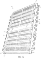
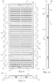
- a conveyor underguard 10 includes a polymeric material body having a generally planar body pan 12 which defines a guard surface 11 is integrally connected to opposed first and second side walls 14, 16, and to first and second end walls 18, 20.
- a first side flange 22 is integrally and frangibly connected to the first side wall 14 and extends for an entire length of the first side wall 14.
- a second side flange 24 is integrally and frangibly connected to the second side wall 16 and extends for an entire length of the second side wall 16.
- the first side flange 22 is flush with respect to an upper perimeter surface 26 of the first and second side walls 14, 16 and the first and second end walls 18, 20. Together, the first and second side flanges 22, 24 define co-planar surfaces 28, 30 which are co-planar with respect to upper perimeter surface 26.
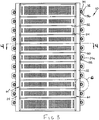
- the body pan 12 can include a longitudinal center rib 36 which is integrally connected to and extends upwardly from body pan 12 for a height which is less than a height of any of the first and second side walls 14, 16 or of the first and second end walls 18, 20. Center rib 36 extends for an entire length of body pan 12 and is integrally connected to each of the first and second end walls 18, 20. Similarly sized first and second side ribs 38, 40 can also be provided in body pan 12, which are constructed the same as center rib 36.
- cross ribs 42 are also integrally connected to body panel 12, and are similar in geometry to center rib 36, but are each oriented normal with respect to center rib 36.
- Each of the cross ribs 42 are integrally connected at opposite ends to the first and second side walls 14, 16.
- the cross ribs serve as flow channels to allow the fluid plastic to flow more easily especially around apertures 46 which will be described in more detail below.
- a gusset 44 is integrally connected at the end of each of the center rib 36, first and second side ribs 38, 40 and the cross ribs 42 where these ribs are integrally connected with individual ones of the walls of body pan 12.
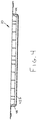
- the gussets 44 provide several functions including: 1) to provide stiffness at the intersections of the walls and the body pan 12; and 2) the gussets 44 of the cross ribs 42 provide wall structure if the body pan 12 is cut proximate to any of the cross ribs 42, which is described in greater detail in reference to Figures 3 and 4 .
- apertures 46 Positioned between any two of the cross ribs 42, such as between cross ribs 42a, 42b are a plurality of apertures 46. Apertures 46 reduce the weight of conveyor underguard 10 as well as the cost by minimizing the amount of resin required to mold conveyor underguard 10. Also, the apertures allow debris to pass through the guard surface 11 so that cardboard dust, and the like, is not allowed to build up on the interior surface portion of the guard surface.
- individual groups of apertures 46 are arranged in longitudinal columns such as apertures 46a provided in a column 48. Similarly, individual groups of apertures 46 are arranged in longitudinal rows such as apertures 46b provided in a row 50. The columns 48 and rows 50 provide maximized use of apertures 46, while maintaining structural integrity of body pan 12.
- a length of body pan 12 can be changed to suit the space requirements of conveyor system without negatively impacting the structural integrity of conveyor underguard 10.
- multiple equally spaced and parallel notches or slots 52 are created in a bottom surface 54 of body pan 12. The slots 52 provide a visual guide for a location to cut body pan 12 when it is desirable to reduce a length of body pan 12.
- each of the mounting flanges 32 are individually frangible and can be individually removed from their respective first or second side flange 22, 24.
- a V-shaped slot 58 is created at the intersection of each mounting flange 32 and an outer edge 60 of either the first or second side flange 22, 24.
- first side flange 22 or second side flange 24 are frangible and can be removed by separation at first and second elongated slots 61, 61' defining a junction between first side flange 22 and body pan 12 and between second side flange 24 and body pan 12.
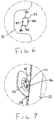
- Conveyor system 62 includes multiple rollers 64 (only one of which is shown for clarity) which are rotatably supported at opposite ends to first and second channel members 66, 68.
- Each channel member 66 or 68 includes an upright member 70, 70' to which is connected the roller 64, and at least a lower flange 72, 72' to which is connected the mounting flanges 32 of one of the first or second side flanges 22, 24.
- a fastener 74 such as a bolt has its fastener head positioned in contact with the raised ring 56 of one of the mounting flanges 32 and its threaded shank 76 extending through the elongated aperture 34 and the lower flange 72 (such as lower flange 72' shown).
- a connecting fastener 78 such as a nut is fixed to threaded shank 76 and the fastener assembly is torqued until the operator "feels" the raised ring 56 begin to compress or collapse. This tactile indication provides a repeatable and substantially equal torque for each of the fastener assemblies.
- the body pan 12 When the conveyor underguard 10 is installed as shown in Figure 5 to an underside of the conveyor system 62, the body pan 12 extends fully across the span between the channel members 66, 68 and prevents personnel from reaching beneath the rollers 64, or into the underside components that may also be installed on conveyor system 62. Body pan 12 also acts to capture light weight objects that fall between any of the rollers 64.
- each of the elongated apertures 34 is provided with opposed first and second end wall raised ribs 80, 82 and opposed first and second side wall raised ribs 84, 86.
- the end wall raised ribs 80, 82 extend toward each other with respect to an inner wall 88 of the elongated aperture 34.
- the first and second side wall raised ribs 84, 86 extend toward each other with respect to the inner wall 88.
- Each of the first and second side wall raised ribs 84, 86 are frictionally contacted by the threaded shank 76 of the fastener 74 and at least one of the first or second end wall raised ribs 80, 82 can also be frictionally contacted by the threaded shank 76.
- This frictional contact temporarily retains the fastener 74 within the elongated aperture 34, such that multiple ones of the fasteners 74 can be installed in conveyor underguard 10 and the entire assembly of conveyor underguard 10 together with the multiple fasteners 74 can be moved into position under the conveyor system 62.
- the elongated apertures 34 are spaced in a predetermined spacing pattern that corresponds to a spacing pattern of apertures created in the lower flanges 72 of the conveyor system 62.
- the pre-installed set of fasteners 74 in conveyor guard 10 therefore axially align with individual ones of the conveyor system lower flange apertures to simplify the installation of conveyor guard 10.
- the raised rings 56 of the mounting flanges 32 provide additional material and stiffness to accommodate the first and second end wall raised ribs 80, 82 and the first and second side wall raised ribs 84, 86. In addition, as previously noted, raised rings 56 also provide a tactile feedback during torqueing of the fasteners 74.
- An alternative conveyor underguard 110 that is not part of the invention includes a guard surface 112 and mounting members 114 each defining a series of spaced apart fastener openings 116 that align with fastener-engaging openings in the bottom flanges of the conveyor side channel (not shown). Fasteners (not shown) pass through-openings 116 to engage the openings in the bottom flanges of the conveyor side channel. Side members 118 space guard surface 112 from mounting members 114 and thereby away from the bottom of the conveyor. Mounting members 114 are each defined by a series of spaced apart tabs 120 each defining a fastener opening 116.
- Guard surface 112 is defined by a plurality of lateral ribs 136 that are spaced apart thereby defining passages 126 that allow debris to fall through guard surface 112.
- An end wall 119 spans between side members 118.
- Spaced apart lateral score lines may be spaced along guard surface 112 to allow the guard to be divided into sections as with conveyor guard 12.
- score lines may be provided along the base of each tab 120 to allow tabs 120 to be individually removed to accommodate conveyor legs or other obstacles.
- Conveyor guard 110 may be made by thermo forming. Thermo forming results in a higher part cost, but a lower mold cost. Thus, it is ideal for low volume sizes.
Landscapes
- Engineering & Computer Science (AREA)
- Mechanical Engineering (AREA)
- Packaging Of Machine Parts And Wound Products (AREA)
- Chain Conveyers (AREA)
- Rollers For Roller Conveyors For Transfer (AREA)
- Structure Of Belt Conveyors (AREA)
- Pallets (AREA)
- Belt Conveyors (AREA)
Claims (5)
- Une protection inférieure (10) de transporteur apte à être utilisée avec un transporteur ayant une paire de canaux latéraux espacés (66, 68), ayant chacun une bride inférieure (72) et une pluralité d'ouvertures sur chacune desdites brides (72), ladite protection inférieure de transporteur comprenant:une surface de protection (11);une paire d'éléments de montage (22, 24) s'étendant chacun vers l'extérieur généralement parallèlement à ladite surface de protection (11) et comprenant des ouvertures de fixation (34), lesdites ouvertures de fixation (34) étant mutuellement espacées de manière à être alignées avec les ouvertures du transporteur; etune paire d'éléments latéraux (14, 16), lesdits éléments latéraux reliant ladite surface de protection (11) auxdits éléments de montage (22, 24) de manière à décaler ladite surface de protection (11) desdits éléments de montage (22, 24) en éloignant ladite surface protection (11) de chaque bride (72),
caractérisée en ce quechacun desdits éléments de montage (22, 24) est défini par une pluralité de languettes, chacune définissant l'une desdites ouvertures de fixation (34), dans laquelle au moins certaines desdites languettes sont reliées de manière cassable à l'un desdits éléments latéraux (14, 16) et adaptées pour être cassées afin d'accommoder des obstructions. - La protection inférieure de transporteur selon la revendication 1, qui est divisée en une pluralité de parties assemblées de manière cassable, chacune étant adaptée pour être retirée d'une section adjacente.
- La protection inférieure de transporteur selon la revendication 2, dans laquelle les parties sont aptes à être enlevées par une ligne d'entaille.
- La protection inférieure de transporteur selon la revendication 1, incluant des nervures latérales (42) s'étendant à travers ladite surface de protection (11).
- La protection inférieure de transporteur selon la revendication 4, dans laquelle au moins certaines desdites nervures latérales (42) sont espacées de manière proche et incluent des lignes d'entaille latérales chacune positionnées entre une paire de nervures latérales (42) espacées de manière proche.
Applications Claiming Priority (3)
| Application Number | Priority Date | Filing Date | Title |
|---|---|---|---|
| US201313837901A | 2013-03-15 | 2013-03-15 | |
| US201361887025P | 2013-10-04 | 2013-10-04 | |
| PCT/US2014/026012 WO2014151566A1 (fr) | 2013-03-15 | 2014-03-13 | Protection inférieure de transporteur |
Publications (3)
| Publication Number | Publication Date |
|---|---|
| EP2969860A1 EP2969860A1 (fr) | 2016-01-20 |
| EP2969860A4 EP2969860A4 (fr) | 2017-01-25 |
| EP2969860B1 true EP2969860B1 (fr) | 2018-10-10 |
Family
ID=51580989
Family Applications (1)
| Application Number | Title | Priority Date | Filing Date |
|---|---|---|---|
| EP14768405.4A Active EP2969860B1 (fr) | 2013-03-15 | 2014-03-13 | Protection inférieure de transporteur |
Country Status (8)
| Country | Link |
|---|---|
| EP (1) | EP2969860B1 (fr) |
| CN (1) | CN105143073A (fr) |
| AU (1) | AU2014233916B2 (fr) |
| BR (1) | BR112015020449A2 (fr) |
| CA (1) | CA2902620C (fr) |
| ES (1) | ES2701528T3 (fr) |
| MX (1) | MX363080B (fr) |
| WO (1) | WO2014151566A1 (fr) |
Family Cites Families (12)
| Publication number | Priority date | Publication date | Assignee | Title |
|---|---|---|---|---|
| US1949817A (en) * | 1931-10-08 | 1934-03-06 | Logan Co Inc | Roller conveyer |
| US3322251A (en) * | 1965-04-19 | 1967-05-30 | Condeco Automation | Flexible gravity conveyor |
| US4081075A (en) * | 1975-06-03 | 1978-03-28 | Puretic Mario J | Fish flume apparatus |
| FR2635509B1 (fr) | 1988-08-22 | 1993-07-30 | Sipa Sa | Rail a galets perfectionne |
| US5078250A (en) * | 1991-01-07 | 1992-01-07 | Sinco, Inc. | Universal safety guard assembly for a conveyor |
| US6000529A (en) * | 1997-12-02 | 1999-12-14 | Span Tech Llc | Underguard assembly for modular conveyors |
| US6193043B1 (en) * | 1999-05-17 | 2001-02-27 | Ancra International Llc | Retractable roller system for handling cargo |
| US7284658B2 (en) * | 2005-01-26 | 2007-10-23 | Argonics, Inc. | Roller safety support system for conveyor system |
| US7383944B2 (en) * | 2006-06-26 | 2008-06-10 | Dorner Mfg. Corp. | Sanitary conveyor center drive assembly |
| US8474608B2 (en) * | 2010-11-24 | 2013-07-02 | Martin Engineering Company | Conveyor belt guard panel blank having integrally formed handles and method of forming a conveyor belt guard panel |
| DE202011050196U1 (de) * | 2011-05-20 | 2011-07-07 | TIS Technischer Industrie Service für Verschleiß- und Fördertechnik GmbH | Untergurtrolleneingreifschutz |
| DE202012102015U1 (de) * | 2012-02-24 | 2012-08-01 | Niederholz Gmbh | Baukastenartig aufgebauter Kettenkratzerförderer |
-
2014
- 2014-03-13 ES ES14768405T patent/ES2701528T3/es active Active
- 2014-03-13 EP EP14768405.4A patent/EP2969860B1/fr active Active
- 2014-03-13 CN CN201480012076.4A patent/CN105143073A/zh active Pending
- 2014-03-13 BR BR112015020449A patent/BR112015020449A2/pt not_active IP Right Cessation
- 2014-03-13 WO PCT/US2014/026012 patent/WO2014151566A1/fr not_active Ceased
- 2014-03-13 CA CA2902620A patent/CA2902620C/fr active Active
- 2014-03-13 MX MX2015012952A patent/MX363080B/es unknown
- 2014-03-13 AU AU2014233916A patent/AU2014233916B2/en active Active
Non-Patent Citations (1)
| Title |
|---|
| None * |
Also Published As
| Publication number | Publication date |
|---|---|
| EP2969860A4 (fr) | 2017-01-25 |
| AU2014233916A1 (en) | 2015-09-17 |
| ES2701528T3 (es) | 2019-02-22 |
| BR112015020449A2 (pt) | 2017-07-18 |
| AU2014233916B2 (en) | 2017-03-23 |
| CN105143073A (zh) | 2015-12-09 |
| MX363080B (es) | 2019-03-07 |
| EP2969860A1 (fr) | 2016-01-20 |
| WO2014151566A1 (fr) | 2014-09-25 |
| MX2015012952A (es) | 2016-07-20 |
| CA2902620C (fr) | 2018-06-12 |
| CA2902620A1 (fr) | 2014-09-25 |
Similar Documents
| Publication | Publication Date | Title |
|---|---|---|
| EP2897882B1 (fr) | Récipient-palette | |
| CA2895767C (fr) | Rail pour chemin de cables | |
| US8899410B2 (en) | Conveyor underguard | |
| US20150034421A1 (en) | Scaffold Deck System With A Float Bar Support For Creating An Opening To Accommodate Obstacles | |
| US9493955B1 (en) | Snow guard assembly for standing seam metal roof | |
| EP2969860B1 (fr) | Protection inférieure de transporteur | |
| EP3556678B1 (fr) | Système de transport pour les roues de guidage des véhicules à deux roues | |
| EP3530594A1 (fr) | Structure réticulaire flexible | |
| EP1930257B1 (fr) | Bande transporteuse résistant à une température élevée dotée de parois latérales. | |
| WO2009009626A1 (fr) | Chemins de roulement, procédés d'utilisation associés, et appareil, système et procédé de fabrication | |
| US7753327B2 (en) | Shelf bracket and method of making same | |
| EP1373105B1 (fr) | Elevateur de stockage a etageres | |
| EP2070842A2 (fr) | Support d'outil, en forme de récipient plastique | |
| WO2004110904A1 (fr) | Ensemble de rouleaux de transporteur | |
| DE212013000171U1 (de) | Regalfach mit Schutzelementen für ein Regallager | |
| EP2149952A1 (fr) | Support pour pluriel mécanismes électrique | |
| US9648974B1 (en) | Baking sheet | |
| EP2288420B1 (fr) | Dispositif de mise en contact d'un gaz et d'un liquide | |
| EP2617321A1 (fr) | Ensemble de rail pour rayonnage mobile | |
| KR200455345Y1 (ko) | 컨베이어 프레임 | |
| EP2185035B1 (fr) | Ensemble de coulisseau pour rayonnage mobile | |
| DE10028588B4 (de) | Stapelbares Transportgebinde für stapelbares Stückgut | |
| EP2850024B1 (fr) | Rail permettant de transporter des marchandises | |
| SE1350709A1 (sv) | Mutteranordning med mutterkista och förskjutbart slädelement | |
| DE20105580U1 (de) | Lagerlift |
Legal Events
| Date | Code | Title | Description |
|---|---|---|---|
| PUAI | Public reference made under article 153(3) epc to a published international application that has entered the european phase |
Free format text: ORIGINAL CODE: 0009012 |
|
| 17P | Request for examination filed |
Effective date: 20150917 |
|
| AK | Designated contracting states |
Kind code of ref document: A1 Designated state(s): AL AT BE BG CH CY CZ DE DK EE ES FI FR GB GR HR HU IE IS IT LI LT LU LV MC MK MT NL NO PL PT RO RS SE SI SK SM TR |
|
| AX | Request for extension of the european patent |
Extension state: BA ME |
|
| DAX | Request for extension of the european patent (deleted) | ||
| A4 | Supplementary search report drawn up and despatched |
Effective date: 20161222 |
|
| RIC1 | Information provided on ipc code assigned before grant |
Ipc: B65G 19/28 20060101AFI20161216BHEP |
|
| STAA | Information on the status of an ep patent application or granted ep patent |
Free format text: STATUS: EXAMINATION IS IN PROGRESS |
|
| 17Q | First examination report despatched |
Effective date: 20180202 |
|
| GRAP | Despatch of communication of intention to grant a patent |
Free format text: ORIGINAL CODE: EPIDOSNIGR1 |
|
| STAA | Information on the status of an ep patent application or granted ep patent |
Free format text: STATUS: GRANT OF PATENT IS INTENDED |
|
| INTG | Intention to grant announced |
Effective date: 20180618 |
|
| GRAS | Grant fee paid |
Free format text: ORIGINAL CODE: EPIDOSNIGR3 |
|
| GRAA | (expected) grant |
Free format text: ORIGINAL CODE: 0009210 |
|
| STAA | Information on the status of an ep patent application or granted ep patent |
Free format text: STATUS: THE PATENT HAS BEEN GRANTED |
|
| AK | Designated contracting states |
Kind code of ref document: B1 Designated state(s): AL AT BE BG CH CY CZ DE DK EE ES FI FR GB GR HR HU IE IS IT LI LT LU LV MC MK MT NL NO PL PT RO RS SE SI SK SM TR |
|
| REG | Reference to a national code |
Ref country code: GB Ref legal event code: FG4D |
|
| REG | Reference to a national code |
Ref country code: CH Ref legal event code: EP Ref country code: AT Ref legal event code: REF Ref document number: 1050965 Country of ref document: AT Kind code of ref document: T Effective date: 20181015 |
|
| REG | Reference to a national code |
Ref country code: IE Ref legal event code: FG4D |
|
| REG | Reference to a national code |
Ref country code: DE Ref legal event code: R096 Ref document number: 602014033869 Country of ref document: DE |
|
| REG | Reference to a national code |
Ref country code: NL Ref legal event code: FP |
|
| REG | Reference to a national code |
Ref country code: ES Ref legal event code: FG2A Ref document number: 2701528 Country of ref document: ES Kind code of ref document: T3 Effective date: 20190222 |
|
| REG | Reference to a national code |
Ref country code: LT Ref legal event code: MG4D |
|
| PG25 | Lapsed in a contracting state [announced via postgrant information from national office to epo] |
Ref country code: NO Free format text: LAPSE BECAUSE OF FAILURE TO SUBMIT A TRANSLATION OF THE DESCRIPTION OR TO PAY THE FEE WITHIN THE PRESCRIBED TIME-LIMIT Effective date: 20190110 Ref country code: BG Free format text: LAPSE BECAUSE OF FAILURE TO SUBMIT A TRANSLATION OF THE DESCRIPTION OR TO PAY THE FEE WITHIN THE PRESCRIBED TIME-LIMIT Effective date: 20190110 Ref country code: PL Free format text: LAPSE BECAUSE OF FAILURE TO SUBMIT A TRANSLATION OF THE DESCRIPTION OR TO PAY THE FEE WITHIN THE PRESCRIBED TIME-LIMIT Effective date: 20181010 Ref country code: FI Free format text: LAPSE BECAUSE OF FAILURE TO SUBMIT A TRANSLATION OF THE DESCRIPTION OR TO PAY THE FEE WITHIN THE PRESCRIBED TIME-LIMIT Effective date: 20181010 Ref country code: LT Free format text: LAPSE BECAUSE OF FAILURE TO SUBMIT A TRANSLATION OF THE DESCRIPTION OR TO PAY THE FEE WITHIN THE PRESCRIBED TIME-LIMIT Effective date: 20181010 Ref country code: IS Free format text: LAPSE BECAUSE OF FAILURE TO SUBMIT A TRANSLATION OF THE DESCRIPTION OR TO PAY THE FEE WITHIN THE PRESCRIBED TIME-LIMIT Effective date: 20190210 Ref country code: LV Free format text: LAPSE BECAUSE OF FAILURE TO SUBMIT A TRANSLATION OF THE DESCRIPTION OR TO PAY THE FEE WITHIN THE PRESCRIBED TIME-LIMIT Effective date: 20181010 Ref country code: HR Free format text: LAPSE BECAUSE OF FAILURE TO SUBMIT A TRANSLATION OF THE DESCRIPTION OR TO PAY THE FEE WITHIN THE PRESCRIBED TIME-LIMIT Effective date: 20181010 |
|
| PG25 | Lapsed in a contracting state [announced via postgrant information from national office to epo] |
Ref country code: SE Free format text: LAPSE BECAUSE OF FAILURE TO SUBMIT A TRANSLATION OF THE DESCRIPTION OR TO PAY THE FEE WITHIN THE PRESCRIBED TIME-LIMIT Effective date: 20181010 Ref country code: AL Free format text: LAPSE BECAUSE OF FAILURE TO SUBMIT A TRANSLATION OF THE DESCRIPTION OR TO PAY THE FEE WITHIN THE PRESCRIBED TIME-LIMIT Effective date: 20181010 Ref country code: RS Free format text: LAPSE BECAUSE OF FAILURE TO SUBMIT A TRANSLATION OF THE DESCRIPTION OR TO PAY THE FEE WITHIN THE PRESCRIBED TIME-LIMIT Effective date: 20181010 Ref country code: GR Free format text: LAPSE BECAUSE OF FAILURE TO SUBMIT A TRANSLATION OF THE DESCRIPTION OR TO PAY THE FEE WITHIN THE PRESCRIBED TIME-LIMIT Effective date: 20190111 Ref country code: PT Free format text: LAPSE BECAUSE OF FAILURE TO SUBMIT A TRANSLATION OF THE DESCRIPTION OR TO PAY THE FEE WITHIN THE PRESCRIBED TIME-LIMIT Effective date: 20190210 |
|
| REG | Reference to a national code |
Ref country code: DE Ref legal event code: R097 Ref document number: 602014033869 Country of ref document: DE |
|
| PG25 | Lapsed in a contracting state [announced via postgrant information from national office to epo] |
Ref country code: CZ Free format text: LAPSE BECAUSE OF FAILURE TO SUBMIT A TRANSLATION OF THE DESCRIPTION OR TO PAY THE FEE WITHIN THE PRESCRIBED TIME-LIMIT Effective date: 20181010 Ref country code: IT Free format text: LAPSE BECAUSE OF FAILURE TO SUBMIT A TRANSLATION OF THE DESCRIPTION OR TO PAY THE FEE WITHIN THE PRESCRIBED TIME-LIMIT Effective date: 20181010 Ref country code: DK Free format text: LAPSE BECAUSE OF FAILURE TO SUBMIT A TRANSLATION OF THE DESCRIPTION OR TO PAY THE FEE WITHIN THE PRESCRIBED TIME-LIMIT Effective date: 20181010 |
|
| PLBE | No opposition filed within time limit |
Free format text: ORIGINAL CODE: 0009261 |
|
| STAA | Information on the status of an ep patent application or granted ep patent |
Free format text: STATUS: NO OPPOSITION FILED WITHIN TIME LIMIT |
|
| PG25 | Lapsed in a contracting state [announced via postgrant information from national office to epo] |
Ref country code: RO Free format text: LAPSE BECAUSE OF FAILURE TO SUBMIT A TRANSLATION OF THE DESCRIPTION OR TO PAY THE FEE WITHIN THE PRESCRIBED TIME-LIMIT Effective date: 20181010 Ref country code: EE Free format text: LAPSE BECAUSE OF FAILURE TO SUBMIT A TRANSLATION OF THE DESCRIPTION OR TO PAY THE FEE WITHIN THE PRESCRIBED TIME-LIMIT Effective date: 20181010 Ref country code: SM Free format text: LAPSE BECAUSE OF FAILURE TO SUBMIT A TRANSLATION OF THE DESCRIPTION OR TO PAY THE FEE WITHIN THE PRESCRIBED TIME-LIMIT Effective date: 20181010 Ref country code: SK Free format text: LAPSE BECAUSE OF FAILURE TO SUBMIT A TRANSLATION OF THE DESCRIPTION OR TO PAY THE FEE WITHIN THE PRESCRIBED TIME-LIMIT Effective date: 20181010 |
|
| 26N | No opposition filed |
Effective date: 20190711 |
|
| PG25 | Lapsed in a contracting state [announced via postgrant information from national office to epo] |
Ref country code: MC Free format text: LAPSE BECAUSE OF FAILURE TO SUBMIT A TRANSLATION OF THE DESCRIPTION OR TO PAY THE FEE WITHIN THE PRESCRIBED TIME-LIMIT Effective date: 20181010 Ref country code: SI Free format text: LAPSE BECAUSE OF FAILURE TO SUBMIT A TRANSLATION OF THE DESCRIPTION OR TO PAY THE FEE WITHIN THE PRESCRIBED TIME-LIMIT Effective date: 20181010 |
|
| REG | Reference to a national code |
Ref country code: CH Ref legal event code: PL |
|
| GBPC | Gb: european patent ceased through non-payment of renewal fee |
Effective date: 20190313 |
|
| PG25 | Lapsed in a contracting state [announced via postgrant information from national office to epo] |
Ref country code: LU Free format text: LAPSE BECAUSE OF NON-PAYMENT OF DUE FEES Effective date: 20190313 |
|
| REG | Reference to a national code |
Ref country code: BE Ref legal event code: MM Effective date: 20190331 |
|
| PG25 | Lapsed in a contracting state [announced via postgrant information from national office to epo] |
Ref country code: CH Free format text: LAPSE BECAUSE OF NON-PAYMENT OF DUE FEES Effective date: 20190331 Ref country code: GB Free format text: LAPSE BECAUSE OF NON-PAYMENT OF DUE FEES Effective date: 20190313 Ref country code: LI Free format text: LAPSE BECAUSE OF NON-PAYMENT OF DUE FEES Effective date: 20190331 Ref country code: IE Free format text: LAPSE BECAUSE OF NON-PAYMENT OF DUE FEES Effective date: 20190313 |
|
| PG25 | Lapsed in a contracting state [announced via postgrant information from national office to epo] |
Ref country code: BE Free format text: LAPSE BECAUSE OF NON-PAYMENT OF DUE FEES Effective date: 20190331 |
|
| PG25 | Lapsed in a contracting state [announced via postgrant information from national office to epo] |
Ref country code: TR Free format text: LAPSE BECAUSE OF FAILURE TO SUBMIT A TRANSLATION OF THE DESCRIPTION OR TO PAY THE FEE WITHIN THE PRESCRIBED TIME-LIMIT Effective date: 20181010 |
|
| PG25 | Lapsed in a contracting state [announced via postgrant information from national office to epo] |
Ref country code: MT Free format text: LAPSE BECAUSE OF NON-PAYMENT OF DUE FEES Effective date: 20190313 |
|
| PG25 | Lapsed in a contracting state [announced via postgrant information from national office to epo] |
Ref country code: CY Free format text: LAPSE BECAUSE OF FAILURE TO SUBMIT A TRANSLATION OF THE DESCRIPTION OR TO PAY THE FEE WITHIN THE PRESCRIBED TIME-LIMIT Effective date: 20181010 |
|
| REG | Reference to a national code |
Ref country code: AT Ref legal event code: UEP Ref document number: 1050965 Country of ref document: AT Kind code of ref document: T Effective date: 20181010 |
|
| PG25 | Lapsed in a contracting state [announced via postgrant information from national office to epo] |
Ref country code: HU Free format text: LAPSE BECAUSE OF FAILURE TO SUBMIT A TRANSLATION OF THE DESCRIPTION OR TO PAY THE FEE WITHIN THE PRESCRIBED TIME-LIMIT; INVALID AB INITIO Effective date: 20140313 |
|
| PG25 | Lapsed in a contracting state [announced via postgrant information from national office to epo] |
Ref country code: MK Free format text: LAPSE BECAUSE OF FAILURE TO SUBMIT A TRANSLATION OF THE DESCRIPTION OR TO PAY THE FEE WITHIN THE PRESCRIBED TIME-LIMIT Effective date: 20181010 |
|
| PGFP | Annual fee paid to national office [announced via postgrant information from national office to epo] |
Ref country code: ES Payment date: 20250429 Year of fee payment: 12 |
|
| PGFP | Annual fee paid to national office [announced via postgrant information from national office to epo] |
Ref country code: DE Payment date: 20260319 Year of fee payment: 13 |
|
| PGFP | Annual fee paid to national office [announced via postgrant information from national office to epo] |
Ref country code: AT Payment date: 20260320 Year of fee payment: 13 |
|
| PGFP | Annual fee paid to national office [announced via postgrant information from national office to epo] |
Ref country code: NL Payment date: 20260319 Year of fee payment: 13 |
|
| PGFP | Annual fee paid to national office [announced via postgrant information from national office to epo] |
Ref country code: FR Payment date: 20260320 Year of fee payment: 13 |