EP2972072B1 - Spannungsmessvorrichtung - Google Patents
Spannungsmessvorrichtung Download PDFInfo
- Publication number
- EP2972072B1 EP2972072B1 EP14720176.8A EP14720176A EP2972072B1 EP 2972072 B1 EP2972072 B1 EP 2972072B1 EP 14720176 A EP14720176 A EP 14720176A EP 2972072 B1 EP2972072 B1 EP 2972072B1
- Authority
- EP
- European Patent Office
- Prior art keywords
- measuring
- test body
- fibres
- measurement
- fiber
- Prior art date
- Legal status (The legal status is an assumption and is not a legal conclusion. Google has not performed a legal analysis and makes no representation as to the accuracy of the status listed.)
- Active
Links
Images


Classifications
-
- G—PHYSICS
- G01—MEASURING; TESTING
- G01B—MEASURING LENGTH, THICKNESS OR SIMILAR LINEAR DIMENSIONS; MEASURING ANGLES; MEASURING AREAS; MEASURING IRREGULARITIES OF SURFACES OR CONTOURS
- G01B11/00—Measuring arrangements characterised by the use of optical techniques
- G01B11/16—Measuring arrangements characterised by the use of optical techniques for measuring the deformation in a solid, e.g. optical strain gauge
- G01B11/18—Measuring arrangements characterised by the use of optical techniques for measuring the deformation in a solid, e.g. optical strain gauge using photoelastic elements
-
- G—PHYSICS
- G01—MEASURING; TESTING
- G01B—MEASURING LENGTH, THICKNESS OR SIMILAR LINEAR DIMENSIONS; MEASURING ANGLES; MEASURING AREAS; MEASURING IRREGULARITIES OF SURFACES OR CONTOURS
- G01B21/00—Measuring arrangements or details thereof, where the measuring technique is not covered by the other groups of this subclass, unspecified or not relevant
- G01B21/32—Measuring arrangements or details thereof, where the measuring technique is not covered by the other groups of this subclass, unspecified or not relevant for measuring the deformation in a solid
-
- G—PHYSICS
- G01—MEASURING; TESTING
- G01L—MEASURING FORCE, STRESS, TORQUE, WORK, MECHANICAL POWER, MECHANICAL EFFICIENCY, OR FLUID PRESSURE
- G01L1/00—Measuring force or stress, in general
- G01L1/24—Measuring force or stress, in general by measuring variations of optical properties of material when it is stressed, e.g. by photoelastic stress analysis using infrared, visible light, ultraviolet
- G01L1/242—Measuring force or stress, in general by measuring variations of optical properties of material when it is stressed, e.g. by photoelastic stress analysis using infrared, visible light, ultraviolet the material being an optical fibre
-
- G—PHYSICS
- G01—MEASURING; TESTING
- G01L—MEASURING FORCE, STRESS, TORQUE, WORK, MECHANICAL POWER, MECHANICAL EFFICIENCY, OR FLUID PRESSURE
- G01L1/00—Measuring force or stress, in general
- G01L1/24—Measuring force or stress, in general by measuring variations of optical properties of material when it is stressed, e.g. by photoelastic stress analysis using infrared, visible light, ultraviolet
- G01L1/242—Measuring force or stress, in general by measuring variations of optical properties of material when it is stressed, e.g. by photoelastic stress analysis using infrared, visible light, ultraviolet the material being an optical fibre
- G01L1/246—Measuring force or stress, in general by measuring variations of optical properties of material when it is stressed, e.g. by photoelastic stress analysis using infrared, visible light, ultraviolet the material being an optical fibre using integrated gratings, e.g. Bragg gratings
-
- G—PHYSICS
- G01—MEASURING; TESTING
- G01L—MEASURING FORCE, STRESS, TORQUE, WORK, MECHANICAL POWER, MECHANICAL EFFICIENCY, OR FLUID PRESSURE
- G01L5/00—Apparatus for, or methods of, measuring force, work, mechanical power, or torque, specially adapted for specific purposes
- G01L5/16—Apparatus for, or methods of, measuring force, work, mechanical power, or torque, specially adapted for specific purposes for measuring several components of force
-
- G—PHYSICS
- G01—MEASURING; TESTING
- G01M—TESTING STATIC OR DYNAMIC BALANCE OF MACHINES OR STRUCTURES; TESTING OF STRUCTURES OR APPARATUS, NOT OTHERWISE PROVIDED FOR
- G01M11/00—Testing of optical apparatus; Testing structures by optical methods not otherwise provided for
- G01M11/08—Testing mechanical properties
- G01M11/083—Testing mechanical properties by using an optical fiber in contact with the device under test [DUT]
- G01M11/086—Details about the embedment of the optical fiber within the DUT
-
- G—PHYSICS
- G01—MEASURING; TESTING
- G01M—TESTING STATIC OR DYNAMIC BALANCE OF MACHINES OR STRUCTURES; TESTING OF STRUCTURES OR APPARATUS, NOT OTHERWISE PROVIDED FOR
- G01M5/00—Investigating the elasticity of structures, e.g. deflection of bridges or air-craft wings
- G01M5/0041—Investigating the elasticity of structures, e.g. deflection of bridges or air-craft wings by determining deflection or stress
-
- G—PHYSICS
- G01—MEASURING; TESTING
- G01M—TESTING STATIC OR DYNAMIC BALANCE OF MACHINES OR STRUCTURES; TESTING OF STRUCTURES OR APPARATUS, NOT OTHERWISE PROVIDED FOR
- G01M5/00—Investigating the elasticity of structures, e.g. deflection of bridges or air-craft wings
- G01M5/0091—Investigating the elasticity of structures, e.g. deflection of bridges or air-craft wings by using electromagnetic excitation or detection
Definitions
- the invention relates to a device for measuring local stresses or strains inside a volume, which can for example represent a structure or a part of a structure.
- the evolution of the deformations of the structures and the estimation of the stresses exerted on them can be followed by devices placed on the external surface of the structures such as visual witnesses for the deformations or mechanical sensors sensitive to the deformation. on the surface of these structures ( FR2855210 ).
- the measurement of the deformation inside the volume itself can be estimated by integrating a uniaxial sensor or "measuring fiber" such as an optical cord in the volume of the structure itself ( WO2006127034 ).
- the integration directly into the monitored volume of a sensor can lead to weakening of the structure which may be due to the difference in mechanical quality of the materials making up the sensor, or to modify the distribution stresses in the volume of the structure near the sensor.
- the particular shape of the sensor can lead to local concentrations of stresses conducive to crack initiation in the vicinity of this sensor.
- the modification of the stress distribution in the very vicinity of the sensor is detrimental to the quality of the measurement, which risks not ideally reflecting the quantities that one wishes to measure [which can lead to the use of these sensors as warnings of thresholds rather than as systems for carrying out monitored measurements].
- the present invention aims to improve the quality and reliability of the measurement of the stresses and deformations exerted locally inside a volume.
- a device for measuring the local stresses and/or deformations inside a measurement volume of a structure of materials having known mechanical properties, the device comprising the characteristics described in independent claim 1 .
- the ellipsoidal-shaped test body may be solid.
- the connecting means are adapted to transmit in the direction of the at least one measurement fiber, a stimulation signal, and to transmit from the at least one measurement fiber a signal originating from an interaction between the measurement fiber and stimulation signal.
- k is equal to 3.
- the measuring device can have several parallel measuring fibers in the same test body.
- the measuring device may comprise three strain measuring fibers or else six strain measuring fibers.
- the measuring device comprises six fibers for measuring deformations and the axes of the measuring fibers are placed substantially perpendicular to the faces of a regular dodecahedron.
- the measurement fibers are sections of the same optical fiber, and the system is suitable for demodulating information carried by the signals coming from the measurement fibers.
- the measuring device further comprises k o deformation measuring fibers, arranged in a non-independent manner in the fibers, where k o is between 1 and k.
- each measuring fiber is attached at its ends to the test body.
- the measuring device comprises an acquisition system arranged downstream of the connection means, and suitable for acquiring and recording said signals.
- the measuring device further comprises a computer connected to the at least one measuring fiber, suitable for determining spatial components of the field of local stresses and/or deformations from the signals.
- the test body of the device is made of an isotropic material.
- the mechanical properties of the material of the test body of the measuring device are identical to those of the sound material constituting the structure.
- the connecting means associated with the measuring device are combined into a single connecting cable.
- the measuring device comprises a plurality of test bodies connected together.
- the connecting means are arranged in the form of a net, comprising nodes at the intersections of the connecting means, a measuring device being fixed at certain nodes or at each node.
- the measuring fiber is a separate component from the test body.
- the measuring optical fiber comprises a waveguide inscribed in the test body.
- the invention also relates to a mechanical structure comprising a measuring volume and a measuring device as described above.
- the device of the invention makes it possible to improve the reliability of the measurement by grouping together the measuring means inside a sub-volume intended to be integrated inside the volume whose evolution it is desired to follow; and made of a material guaranteeing good transmission of the quantities measured to the detector.
- the device of the invention makes it possible, by integrating several deformation sensors in a suitable test body, to measure values related to the components of the deformation tensor in the volume of the sensor, considered to be small compared to that of structure.
- the anisotropy properties of the materials are taken into account to estimate these components.
- the examples of the present device take advantage of this result by proposing to include in a measurement volume with previously known mechanical properties, a test body of ellipsoidal shape so that the values of the deformation field therein are substantially uniform and reflect the values of these fields in the measurement volume.
- the ellipsoidal-shaped test body is solid.
- test body can be integrated into the structure by any appropriate means.
- the test body may have a surface provided with roughness or hairs or growths for attachment.
- the measurement volume is large enough relative to the test body for the variation in the values of the stresses in the test body to be small relative to the desired accuracy of the measurement.
- the device of the invention integrating a plurality of deformation sensors into this test body then makes it possible to simultaneously measure therein several values linked to the deformation tensor.
- the use of the device of the invention makes it possible, as a direct consequence, to avoid causing singularities in the stress field when it is included in a measurement volume. This avoids generating local stress concentrations conducive to crack initiation in the vicinity of the test body.
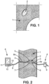
- FIG. 1 schematically represents a part of a structure 1, for which it is desired to determine a deformation or a mechanical stress at a localized location 2.
- the structure 1 is for example a rigid structure, such as a civil engineering structure, in particular made of concrete, where appropriate hollowed out and/or reinforced in places.
- the structure comprises, at the location 2, a recess of specific shape, adapted to receive a test body as will be described later. Furthermore, at least one channel 3 is provided to connect the recess to an instrumentation zone 4.
- the instrumentation zone 4 is for example a zone outside the structure 1, or a hollow zone inside the latter, or accessible from outside the latter for example.
- 2 instrumentation zones 4 and two channels 3 are provided on either side of the structure 1, although this is only an example.
- the channels 3 have small transverse dimensions relative to the recess, and are of sufficient length to extend from the recess to the instrumentation zone.
- the system comprises a test body 5 placed in the recess, which will be described in more detail below, in relation to the figure 8 .
- the outer periphery 18 of the test body 5 is fixed to the inner periphery of the structure 1 at the level of the recess, so as to conduct the stresses exerted in the structure 1 to the test body 5.
- the body of test is fixed in an integral way on the totality of its external circumference to the structure (apart from the places of connection to the channels 3, as explained below).
- the test body 5 is pierced with at least one channel 6, as shown in the figure 2 , which extends in communication with channel 3.
- the system comprises a measuring fiber 7, which extends in channel 6.
- the measuring fiber 7 extends both in channel 6 and in the channel or channels 3 in communication with that -this.
- the measurement fiber 7 is fixed inside the test body 5, so that the stresses exerted in the test body are transmitted to the measurement fiber 7. It is thus intrinsic that apart from the channel 6 or channels 6, test body 5 is full.
- the measuring fiber 7 is fixed by its ends 7' and 7" to the test body 5, close to the surface of the ellipsoid. This fixing can be done with the measuring fiber 7 slightly pre-stressed in traction when the test body 5 is at rest Alternatively, the measuring fiber 7 could be embedded in the test body 5.
- a continuous optical fiber 8 is provided which extends from the instrumentation zone 4 inside channel 3, inside channel 7, inside second channel 3 and into the other instrumentation zone 4.
- the measuring fiber 7 extends straight inside the test body, in a given axis direction.
- the channels 3 extend in any suitable direction, in particular to adapt to natural channels of the structure.
- the measuring fiber 7 comprises for example an active zone 7', for example equidistant from the ends 7' and 7''.
- the active zone has an elasto-optical characteristic, that is to say that its optical transmission depends on its tension along the axis of the fiber 7.
- a network is provided of Bragg likely to deform according to the mechanical stresses exerted on the fiber.
- the system also comprises an interrogation system comprising a stimulation device 9, adapted to emit an optical signal in the direction of the measurement fiber 7. This signal is transmitted via the part 8a of the optical fiber 8 which is extends from the stimulation device 9 to the test body.
- the system also comprises an acquisition system 10, suitable for detecting an optical signal coming from the measurement fiber 7. This signal is transmitted via the part 8b of the optical fiber 8 which extends from the body of test with the acquisition device 10.
- the system also comprises a computer 11.
- the computer is for example produced on a printed circuit of a programmable machine, such as a computer, or the like, and is suitable for processing the signals detected by the acquisition system 10, as will be described in more detail below.
- the computer 11 can process information, such as data stored in a memory 12, corresponding to signals detected by the acquisition device 10, to determine a stress exerted in the structure 1 at the level of the measurement fiber 7 If the fiber of measurement 7 is fixed in the test body, the stress corresponds to an average stress along the axis of the fiber of measurement 7 but also, thanks to the relations resulting from Eshelby's theorem, to the stress at any point inside the test body.
- test body is small compared to those of the structure (which will be classically the case in civil engineering, the dimension of the test body being for example between approximately 0.5 cm and 10 cm, and the dimension of the structure being at least equal to one meter, sometimes greater than 10 or even 100 meters) , we obtain a local measurement at the scale of the structure.
- the computer 11 is also suitable for determining the stresses in the structure at the location of the measurement fiber, from the stress in the optical fiber.
- the computer 11 can include in memory a table comprising the mechanical characteristics of the test body. These characteristics will typically include the modulus(ies) of elasticity for each of the main directions of the material, or even the Poisson's ratio(s) in this frame of reference, if necessary according to certain numbers of external parameters (temperature, etc.) .
- an ellipsoidal inclusion 2 made of a homogeneous and isotropic material whose elasticity tensor is C. Implicitly, it is understood that an ellipsoidal inclusion made of a homogeneous material is full.
- the sensitive parts of the fibers are preferably placed relatively far from the surface of the ellipsoid (therefore towards the interior) in order to smooth the stress field in the structure.
- the ellipsoidal shape also makes it possible not to create a concentration of stresses capable of causing cracking of the structure.
- the measured deformation can be associated with the average state of tension (traction or compression) along the direction of the measurement fiber.
- space is considered to have six dimensions. These are three principal axis dimensions, as well as three dimensions associated with pairs of these axes.
- ⁇ I ⁇ ij n I i n I j , where n I i , n I j designate the i th , respectively the j th component of the vector n I and ⁇ ij the component ( i ,j ) of the strain tensor.
- the stress tensor of interest for the system is that which would exist in the structure in the absence of the sensor: it is called ⁇ 0 . It is related to the measured stress tensor ⁇ by the Eshelby equations quoted above (they are notably simpler in the case of a spherical sensor). Thus we determine ⁇ 0 from ⁇ by the Eshelby equation.
- the measurement of the deformation ⁇ I of the fiber can be obtained by measuring the optical index variation.
- the other components of the tensor e will either be linked to ⁇ and to the elasticity characteristics by an Eshelby calculation (this time for a cylindrical inclusion) in the case where the fiber is "stuck" to the matrix or will simply be linked to the characteristics elastics of the fiber (its Poisson's ratio in the case where it is mechanically isotropic) in the case where it is simply attached at its ends.
- the characteristics elastics of the fiber its Poisson's ratio in the case where it is mechanically isotropic
- test bodies appearing more particularly on the figures 1, 2 , 3 And 6 are of ellipsoidal shape but can be chosen to be spherical used for example in cases where one does not wish to introduce a privileged direction for measurements in an isotropic medium or if one cannot control the orientation of this test body during the inclusion of the test body in the structure.
- shape chosen could be an elongated ellipsoid along one or two particular directions in space and meet a need for measurement along preferred directions in space.
- the material constituting the ellipsoid can be chosen to be isotropic so as to transmit the stresses in an identical manner in all directions of space but could for certain applications be chosen to be anisotropic, that is to say say to behave mechanically in different ways according to one or more dimensions of space. This latter case could, for example, apply to situations where the quantities measured present differences in their magnitude or in the treatment given to them during the acquisition of the measurements, or in the case where the material constituting the structure is himself anisotropic.
- the constituent material can be chosen to be homogeneous at least with respect to the dimensions of the measurement length of the optical measurement fibers so as to avoid local variations during the transmission of the stresses of the test body to the measurement fibers.
- test body also has the additional advantage of making it possible to choose a material that is particularly suited to the transmission of stresses from the measurement volume to the measurement fiber. It thus makes it possible to measure the quantities present in a measurement volume which would be made of a material that is not conducive to the integration of measurement fibers. This may be the case for a material of the measurement volume which is inhomogeneous or has discontinuities or is simply unsuitable for ensuring a mechanical junction with the material constituting the exterior of the measurement fiber.
- the material chosen to produce the test body can be chosen so as to optimize the precision of the measuring device, for example by having mechanical properties very close to or identical to those of the measuring volume.
- test bodies included in a measurement volume which represents a structure should preferably not result in embrittlement of the material.
- the material chosen to constitute the test body could be chosen according to the application envisaged for, on the one hand, the implementation and, on the other hand, for the manufacture of the measuring device.
- the choices can be made on fine concretes (for example of the Ductal type), resins which can be loaded with reinforcements so as to produce composites whose composition makes it possible to adjust their properties mechanics, metals, glasses or ceramics.
- the fibers can be introduced by drilling or by overmoulding.
- additional criteria for choosing the material of the test body can be linked to durability, toxicity or cost.
- a stimulation device 9, LASER type emits an optical signal in the optical fiber.
- the optical signal is propagated along the optical fiber and through the measurement fiber 7, where it is modulated according to the mechanical stresses exerted on the fiber 7.
- the modulated optical signal is transmitted along the optical fiber 8b until to a detector 10, for example of the CDD type, where the signal is detected, then stored in the memory 12 of the computer. It will be noted that such a transmission is possible even in the event of deformations at the level of the test body, since the measurement fibers 7 operate as waveguides.
- the computer processes the information to determine a stress in the structure 1 at the level of the test body.
- This interrogation can be repeated over time, for example periodically.
- the computer is capable of monitoring a temporal evolution of the local stress exerted.
- the computer can be coupled to alert means in the event that a comparison of the detected stresses with a predetermined stress was not deemed satisfactory.
- two measurement fibers 7a and 7b are arranged along two independent axes (in particular two normal axes defining a measurement plan).
- the embodiment of this figure also differs from the first embodiment in that an integrated system performs both the stimulation and the acquisition.
- the optical signal transmitted by the optical fiber is not detected, but the reflection of this signal.
- channel 3 groups together the 2 optical fibers addressing each of the measurement fibers within an optical cable. The diameter of this type of cable remains small compared to the dimensions of the test body, and a fortiori of the structure.
- the test body comprises 3 fibers measuring 7a, 7b, 7c, arranged in 3 independent directions, for example normal to the faces of a cube 13.
- the fibers are spaced slightly apart so as not to be concurrent.
- measurement fibers 7a-7f there are 6 measurement fibers 7a-7f. These are arranged for example according to the normals to the faces of a regular dodecahedron. These 6 measurements constitute 6 independent variables which make it possible to determine the 6 components of the stress tensor in the structure at the location of the test body, by solving a system of 6 equations with 6 unknowns. For example, 6 optical fibers will be used, more or less wound around the test body, and grouped together in the same optical cable running in a channel 3.
- an optical fiber which has a first section 8a extending from the stimulation device to the test body, and a second section forming a first measurement fiber stimulable at a given wavelength, as in the embodiment of the figure 1 .
- an additional section 8c is provided which will wrap around the test body to connect the first measurement fiber to a second measurement fiber extending along a second direction.
- the second measurement fiber is stimulable at a second wavelength distant from the first. This is done to connect the desired number of measurement fibers, before connecting at the output to the detector 10.
- the stimulation can thus comprise an addition of signals having different characteristics, and the detection is capable of demodulating the signal in order to attribute to each fiber measures the part of the signal that is specific to it.
- Such an embodiment is possible for between 2 and 6 measurement fibers, or even more if necessary.
- the above description relates to a single location of the structure 1. As shown alternatively in the figure 6 , the same system can be reproduced for a set of slots 2 of the structure 1. This applies to any of the embodiments described above. If necessary, a single stimulation 9 and detection 10 system and a single computer 11 are used.
- the test bodies 5 are interconnected by optical cables located in channels 3 extending between the different locations.
- the spectral modulation described above does not necessarily apply only to the case of two fiber portions of the same test body extending in two different directions.
- the present embodiments can be integrated into an existing structure, for example by making an ellipsoidal-shaped location in the structure, by digging at least one channel, or even channels extending on either side of this shape, by stretching an optical fiber in this or these channels, the active part of the fiber extending at the level of the ellipsoidal-shaped location, then by injecting a liquid product capable of solidifying (for example a concrete of known mechanical properties) into the location in order to drown the fiber there.
- a liquid product capable of solidifying for example a concrete of known mechanical properties
- a two-dimensional net 15 is provided comprising different test bodies 5 arranged for example in rows and columns and interconnected by optical cables 16 according to a diagram similar to that described on the figure 6 .
- a three-dimensional net is also possible.
- each optical cable 16 can for example comprise a set of n times 6 optical fibers, where n represents the number of test bodies along the axis. 6 of the optical fibers each address one of the 6 channels of a test body while the other optical fibers pass next to it. At the output, all the fibers are again grouped together and directed towards the next test body, where 6 other fibers each address a respective channel of this one, and so on.
- a vertical optical cable 16 addresses all of the test bodies 14 of a column. The ends of the vertical cables are bundled together and routed to a stimulation/acquisition system such as previously described. If necessary, the vertical cables are connected together by holding elements 17 which, in this example, are not necessarily optical.
- an optical fiber can address each of the 6 channels of the same test body, as indicated above, where the same channel of all the test bodies, and the information will be obtained by spectral or spatial analysis , as indicated above.
- the cables 17 could also be optical cables addressing certain channels of certain test bodies.
- the implementation of such a net can easily be varied to adapt to the specificities of the measurement to be performed.
- several such nets can be proposed arranged one behind the other with a certain spacing, in the plane normal to that of the figure 7 . This net can be fixed in the concrete of a structure being manufactured.
- the optical fiber is embedded in a concrete test body, itself intended to be integrated into a concrete structure.
- the invention could be applied in other types of structures.
- composite structures made of plastics reinforced with fibers, in particular glass fibers are known.
- the fact of using optical fibers, therefore in particular made of glass, to implement the above detection, is of particular interest for adapting the above system to such composite systems.
- the measurement part of the optical fiber can then be embedded in a plastic of the kind used in such structures, and the rest of the optical fiber can have mechanical properties similar to those of the fibers of the composite material.
- such structures comprise fibers most often extending in planes, and that, for this kind of application, there is a risk of preferably using the embodiments making it possible to determine the components of the stress tensor in this plane.
- the computer may be provided with communication means, wireless if necessary, to transmit an alarm signal to a monitoring center. Consequently, the computer can be integrated into the structure, or even into a test body.
- the detector may be provided with communication means, where appropriate wireless, to transmit the measured signals to a remote computer. If necessary, the computer could be divided into two parts communicating with each other by means of communication, if necessary wireless.
- a temperature sensor could be placed within or close to the test body, and an electric cable transmitting a local measured temperature value to the central unit. This temperature can be taken into account in the stress calculation.
- measuring fiber which is a separate component of the test body assembled to the test body by being inserted through a channel of the test body and fixed thereto. This.
- a measuring fiber could be made directly integrated into the test body.
- test body 5 thus formed can be arranged in the structure with the integrated inscribed waveguide which has just been described in correspondence with connecting optical fibers 8 arranged in the channels 3 and leading to the stimulation system 9 and/or detection 10.
- the stimulation 9 and/or detection 10 systems can be integrated into the test body 5, in one or the other of the variants proposed above.
- the means for connecting the measurement fiber 7 or the waveguide inscribed with the stimulation 9 and/or detection 10 system can comprise any means for fixing the stimulation 9 and/or detection 10 system allowing to fix it in correspondence with the measuring fiber 7, for example by gluing or mechanical fixing to the test body.
- the stimulation 9 and/or detection 10 systems can be connected by one or more electric wire(s) 19 to the outside, in particular for the power supply.
- the detection system 10 can be connected to the outside, by wired or wireless connection means, for the transmission of measurements.
- the computer 11 When the computer 11 is integrated into a test body, as described above, it can be connected by one or more electrical wire(s) 19 to the outside, in particular for the power supply. He can be connected to the outside, by wired or wireless connection means, for the transmission of results.
- transmission by acoustic waves can be provided.
- the electric wires can be configured in nets for example as represented on the figure 6 And 7 .
Landscapes
- Physics & Mathematics (AREA)
- General Physics & Mathematics (AREA)
- Engineering & Computer Science (AREA)
- Aviation & Aerospace Engineering (AREA)
- Chemical & Material Sciences (AREA)
- Analytical Chemistry (AREA)
- Electromagnetism (AREA)
- Length Measuring Devices By Optical Means (AREA)
- Investigating Strength Of Materials By Application Of Mechanical Stress (AREA)
- Optical Transform (AREA)
Claims (14)
- Vorrichtung zur Messung von lokalen Spannungen und/oder Deformationen innerhalb eines Messvolumens (2) einer Struktur (1) aus Materialien, die bekannte mechanische Eigenschaften aufweisen, wobei die Vorrichtung umfasst:- einen ellipsoidförmigen Prüfkörper (5), der in das Messvolumen (2) eingeschlossen werden soll und aus homogenem Material mit bekannten mechanischen Eigenschaften besteht,- k Deformationsmessfasern (7, 7a-7f), die in k unabhängigen Richtungen angeordnet und im Inneren des Prüfkörpers (5) befestigt sind, so dass Deformationen des Prüfkörpers (5) auf die Messfasern (7, 7a-7f) übertragen werden, wobei k zwischen 2 und 6 liegt,- Mittel (8, 8a-8c) zum Verbinden der k Messfasern (7, 7a-7f) mit einem System (9, 10, 11), das dazu ausgebildet ist, Signale von den Messfasern (7, 7a-7f) zu erfassen, die repräsentativ für die Deformationen der Messfasern (7, 7a-7f) sind, und die lokalen Spannungen und/oder Deformationen aus wenigstens den erfassten Signalen und den bekannten mechanischen Eigenschaften der Materialien des Prüfkörpers (5) und der Struktur (1) zu bestimmen, wobei die k Messfasern (7, 7a-7f) dazu angeordnet sind, unabhängige Komponenten des Spannungstensors in dem Prüfkörper (5) zu bestimmen.
- Vorrichtung nach Anspruch 1, wobei die Messfasern optische Messfasern (7, 7a-7f) sind, wobei die Verbindungsmittel (8, 8a-8c) dazu ausgebildet sind, die Messfasern mit einem System (9) zu verbinden, das dazu ausgebildet ist, die optischen Messfasern (7, 7a-7f) zu stimulieren.
- Vorrichtung nach Anspruch 2, wobei die Verbindungsmittel Vorrichtungen sind, die optische Fasern (8, 8a-8c) in optischer Verbindung mit den Messfasern (7, 7a-7f) umfassen.
- Vorrichtung nach Anspruch 3, wobei die Verbindungsmittel (8, 8a-8c) dazu ausgebildet sind, ein Stimulationssignal in Richtung der Messfasern (7, 7a-7f) zu übertragen und von den Messfasern (7, 7a-7f) ein Signal zu übertragen, das aus einer Wechselwirkung zwischen den Messfasern (7, 7a-7f) und dem Stimulationssignal stammt.
- Vorrichtung nach einem der vorhergehenden Ansprüche, welche eines der folgenden Merkmale aufweist:- k ist gleich 3;- k ist gleich 6 und die Achsen der Messfasern (7, 7a-7f) sind im Wesentlichen senkrecht zu den Flächen eines regelmäßigen Dodekaeders angeordnet.
- Vorrichtung nach einem der vorhergehenden Ansprüche, welche ferner ko zusätzliche Deformationsmessfasern umfasst, die nicht unabhängig voneinander in den Messfasern (7, 7a-7f) angeordnet sind, wobei ko zwischen 1 und k liegt.
- Vorrichtung nach einem der vorhergehenden Ansprüche, wobei jede Messfaser (7, 7a-7f) an ihren Enden (7', 7") am Prüfkörper (5) befestigt ist.
- Vorrichtung nach einem der vorhergehenden Ansprüche, welche ferner das eine und/oder das andere der folgenden Merkmale aufweist:- ein Erfassungssystem (10), welches stromabwärts von den Verbindungsmitteln (8, 8a-8c) angeordnet und dazu ausgebildet ist, die genannten Signale zu erfassen und aufzuzeichnen;- einen Rechner (11), der mit der wenigstens einen Messfaser (7, 7a-7f) verbunden ist und dazu ausgebildet ist, aus den Signalen räumliche Komponenten des lokalen Spannungs- und/oder Deformationsfeldes zu bestimmen.
- Vorrichtung nach einem der vorhergehenden Ansprüche, wobei das Material, das den Prüfkörper (5) bildet, isotrop ist.
- Vorrichtung nach einem der vorhergehenden Ansprüche, wobei die mechanischen Eigenschaften des Materials, das den Prüfkörper (5) bildet, identisch mit denen des die Struktur (1) bildenden gesunden Materials sind.
- Vorrichtung nach einem der vorhergehenden Ansprüche, wobei die Verbindungsmittel (8, 8a-8c) zu einem einzigen Verbindungskabel zusammengefasst sind.
- Vorrichtung nach einem der vorhergehenden Ansprüche, welche eine Vielzahl von miteinander verbundenen Prüfkörpern (5) umfasst.
- Vorrichtung nach einem der vorhergehenden Ansprüche, welche ferner eines der folgenden Merkmale aufweist:- Die Messfaser ist ein vom Prüfkörper getrenntes Bauteil, das mit dem Prüfkörper verbunden ist, indem es durch einen Kanal des Prüfkörpers eingeführt und an dem Kanal des Prüfkörpers befestigt wird;- Die optische Messfaser umfasst einen Wellenleiter, der in den Prüfkörper eingetragen ist.
- Mechanische Struktur (1), die ein Messvolumen (2) und eine Messvorrichtung nach einem der Ansprüche 1 bis 13 umfasst.
Applications Claiming Priority (2)
| Application Number | Priority Date | Filing Date | Title |
|---|---|---|---|
| FR1352216A FR3003346B1 (fr) | 2013-03-13 | 2013-03-13 | Capteur a fibre optique |
| PCT/FR2014/050585 WO2014140496A1 (fr) | 2013-03-13 | 2014-03-13 | Dispositif de mesure de contraintes |
Publications (2)
| Publication Number | Publication Date |
|---|---|
| EP2972072A1 EP2972072A1 (de) | 2016-01-20 |
| EP2972072B1 true EP2972072B1 (de) | 2023-05-17 |
Family
ID=48521286
Family Applications (1)
| Application Number | Title | Priority Date | Filing Date |
|---|---|---|---|
| EP14720176.8A Active EP2972072B1 (de) | 2013-03-13 | 2014-03-13 | Spannungsmessvorrichtung |
Country Status (5)
| Country | Link |
|---|---|
| US (1) | US10030967B2 (de) |
| EP (1) | EP2972072B1 (de) |
| CN (1) | CN105229410B (de) |
| FR (1) | FR3003346B1 (de) |
| WO (1) | WO2014140496A1 (de) |
Families Citing this family (10)
| Publication number | Priority date | Publication date | Assignee | Title |
|---|---|---|---|---|
| FR3047308B1 (fr) * | 2016-02-02 | 2018-02-16 | Saipem S.A. | Procede de surveillance du comportement thermomecanique d'une conduite sous-marine de transport de fluides sous pression |
| FR3050818B1 (fr) * | 2016-04-29 | 2020-02-21 | Centre National De La Recherche Scientifique - Cnrs - | Dispositif de mesure de deformations endogenes |
| KR101889977B1 (ko) * | 2016-12-19 | 2018-08-20 | (주)에프비지코리아 | 광섬유 격자센서를 이용한 변위 측정장치 및 그의 감도 및 내구성 조절방법 |
| FR3070499B1 (fr) * | 2017-08-31 | 2019-09-06 | Saipem S.A. | Procede de determination des variations de contraintes au cours du temps d'une conduite sous-marine de transport de fluides |
| EP3819619B1 (de) * | 2019-11-11 | 2024-06-26 | Bayerische Motoren Werke Aktiengesellschaft | Vorrichtung und verfahren zur überwachung der last oder der integrität eines mechanischen objekts |
| CN112432724B (zh) * | 2020-12-01 | 2022-04-15 | 东北林业大学 | 基于光纤谐振腔游标效应的应力传感器及应力测量方法 |
| FR3117582B1 (fr) | 2020-12-11 | 2022-11-11 | Univ Nantes | Dispositif tridimensionnel de mesure des deformations locales |
| FR3157531A1 (fr) | 2023-12-22 | 2025-06-27 | Commissariat A L'energie Atomique Et Aux Energies Alternatives | Dispositif de mesure de variations d’effort, de déformations mécaniques, de pressions hydrostatiques et de température, et procédé de mesure associé |
| WO2025131752A1 (fr) | 2023-12-22 | 2025-06-26 | Commissariat A L'energie Atomique Et Aux Energies Alternatives | Dispositif de mesure de variations d'effort, de deformations mecaniques, de pressions hydrostatiques et de temperature, et procede de mesure associe |
| CN120778262B (zh) * | 2025-08-01 | 2026-04-28 | 武汉理工大学 | 一种基于光纤传感的水轮机主轴应力测量装置及使用方法 |
Family Cites Families (6)
| Publication number | Priority date | Publication date | Assignee | Title |
|---|---|---|---|---|
| JP2560260B2 (ja) * | 1994-10-05 | 1996-12-04 | 科学技術庁防災科学技術研究所長 | レーザひずみ計 |
| US6696974B1 (en) * | 2000-07-28 | 2004-02-24 | James I. Mathis | Cable device for detecting and monitoring rock and soil displacement |
| FR2850745B1 (fr) * | 2003-01-31 | 2005-04-01 | Commissariat Energie Atomique | Extensometre a corps d'epreuve flexible et reseaux de bragg |
| BRPI0822792B1 (pt) * | 2008-09-23 | 2019-04-16 | Voith Patent Gmbh | Rolo industrial com sistema sensor de cobertura do rolo ótico |
| CN102288122B (zh) * | 2011-04-22 | 2012-11-14 | 中国航空工业集团公司北京长城计量测试技术研究所 | 一种用于光纤光栅应变传感器的在线校准装置和方法 |
| CN202158841U (zh) * | 2011-07-08 | 2012-03-07 | 中国飞机强度研究所 | 一种光纤光栅应变传感器 |
-
2013
- 2013-03-13 FR FR1352216A patent/FR3003346B1/fr not_active Expired - Fee Related
-
2014
- 2014-03-13 CN CN201480020898.7A patent/CN105229410B/zh not_active Expired - Fee Related
- 2014-03-13 US US14/775,506 patent/US10030967B2/en active Active
- 2014-03-13 EP EP14720176.8A patent/EP2972072B1/de active Active
- 2014-03-13 WO PCT/FR2014/050585 patent/WO2014140496A1/fr not_active Ceased
Also Published As
| Publication number | Publication date |
|---|---|
| EP2972072A1 (de) | 2016-01-20 |
| FR3003346B1 (fr) | 2016-01-29 |
| US10030967B2 (en) | 2018-07-24 |
| US20160202133A1 (en) | 2016-07-14 |
| FR3003346A1 (fr) | 2014-09-19 |
| WO2014140496A1 (fr) | 2014-09-18 |
| CN105229410B (zh) | 2018-05-29 |
| CN105229410A (zh) | 2016-01-06 |
Similar Documents
| Publication | Publication Date | Title |
|---|---|---|
| EP2972072B1 (de) | Spannungsmessvorrichtung | |
| EP3555585B1 (de) | Verfahren und system zur steuerung der integrierten gesundheit einer mechanischen struktur durch diffuse elastische wellen | |
| EP0214213B1 (de) | Optischer kraftsensor, verfahren zum messen einer kraft mit diesem gerät und seine anwendung bei einer waage | |
| EP1723458B1 (de) | System zur verteilten messung von strukturbiegungen | |
| EP3707503B1 (de) | Überwachung der strukturellen gesundheit für eine industriestruktur | |
| EP3077795B1 (de) | Prüfung einer industriestruktur | |
| RU2540258C1 (ru) | Устройство для измерения деформаций и способ измерения деформаций | |
| WO2016020595A1 (fr) | Procédé et dispositif pour la détermination de la profondeur de l'origine d'un tassement de sol | |
| FR2855210A1 (fr) | Logement sur l'exterieur d'un cuvelage de puits pour capteur a fibre optique | |
| FR2815118A1 (fr) | Mesure de contrainte dans les puits d'hydrocarbures | |
| EP0546899A1 (de) | Eigenschaden-Kontrollvorrichtung und Verfahren zur Herstellung und Anwendung | |
| EP3449208B1 (de) | Vorrichtung zur messung von endogenen deformationen | |
| CA2655240A1 (fr) | Capteur a base de fibre optique microstructuree et a reseau de bragg | |
| EP4260001B1 (de) | Dreidimensionale vorrichtung zur messung von lokalen verformungen | |
| WO2025131752A1 (fr) | Dispositif de mesure de variations d'effort, de deformations mecaniques, de pressions hydrostatiques et de temperature, et procede de mesure associe | |
| FR3117215A1 (fr) | Imagerie de guides d’ondes élastiques interconnectés par une jonction | |
| FR2827670A1 (fr) | Procede et dispositif de veille sismique | |
| Wang et al. | Nondestructive refractive index measurement based on computational light-in-flight imaging | |
| Cappelli et al. | Impact of Cable Structure on Distributed Fiber Optic Sensing | |
| WO2015118066A1 (fr) | Procede de suivi d'une intervention dans un puits d'exploitation de fluide menage dans le sous-sol, et dispositif d'intervention associe | |
| Augusciuk et al. | Testing biological liquid samples using modified m-line spectroscopy method | |
| Rizk | Strain sensing in underwater acoustics with a hybrid π-shifted FBG and different interrogation methods |
Legal Events
| Date | Code | Title | Description |
|---|---|---|---|
| PUAI | Public reference made under article 153(3) epc to a published international application that has entered the european phase |
Free format text: ORIGINAL CODE: 0009012 |
|
| 17P | Request for examination filed |
Effective date: 20150911 |
|
| AK | Designated contracting states |
Kind code of ref document: A1 Designated state(s): AL AT BE BG CH CY CZ DE DK EE ES FI FR GB GR HR HU IE IS IT LI LT LU LV MC MK MT NL NO PL PT RO RS SE SI SK SM TR |
|
| AX | Request for extension of the european patent |
Extension state: BA ME |
|
| DAX | Request for extension of the european patent (deleted) | ||
| STAA | Information on the status of an ep patent application or granted ep patent |
Free format text: STATUS: EXAMINATION IS IN PROGRESS |
|
| 17Q | First examination report despatched |
Effective date: 20191218 |
|
| REG | Reference to a national code |
Ref country code: DE Ref legal event code: R079 Free format text: PREVIOUS MAIN CLASS: G01B0011160000 Ipc: G01B0021320000 Ref document number: 602014086966 Country of ref document: DE |
|
| RIC1 | Information provided on ipc code assigned before grant |
Ipc: G01L 5/16 20060101ALI20221010BHEP Ipc: G01M 11/08 20060101ALI20221010BHEP Ipc: G01M 5/00 20060101ALI20221010BHEP Ipc: G01L 1/24 20060101ALI20221010BHEP Ipc: G01B 11/16 20060101ALI20221010BHEP Ipc: G01B 21/32 20060101AFI20221010BHEP |
|
| GRAP | Despatch of communication of intention to grant a patent |
Free format text: ORIGINAL CODE: EPIDOSNIGR1 |
|
| STAA | Information on the status of an ep patent application or granted ep patent |
Free format text: STATUS: GRANT OF PATENT IS INTENDED |
|
| INTG | Intention to grant announced |
Effective date: 20221205 |
|
| RIN1 | Information on inventor provided before grant (corrected) |
Inventor name: LUPI, CYRIL Inventor name: LEDUC, DOMINIQUE Inventor name: LECIEUX, YANN Inventor name: FRANCOIS, MARC |
|
| GRAS | Grant fee paid |
Free format text: ORIGINAL CODE: EPIDOSNIGR3 |
|
| GRAA | (expected) grant |
Free format text: ORIGINAL CODE: 0009210 |
|
| STAA | Information on the status of an ep patent application or granted ep patent |
Free format text: STATUS: THE PATENT HAS BEEN GRANTED |
|
| RAP1 | Party data changed (applicant data changed or rights of an application transferred) |
Owner name: NANTES UNIVERSITE |
|
| AK | Designated contracting states |
Kind code of ref document: B1 Designated state(s): AL AT BE BG CH CY CZ DE DK EE ES FI FR GB GR HR HU IE IS IT LI LT LU LV MC MK MT NL NO PL PT RO RS SE SI SK SM TR |
|
| REG | Reference to a national code |
Ref country code: GB Ref legal event code: FG4D Free format text: NOT ENGLISH |
|
| REG | Reference to a national code |
Ref country code: CH Ref legal event code: EP |
|
| REG | Reference to a national code |
Ref country code: DE Ref legal event code: R096 Ref document number: 602014086966 Country of ref document: DE |
|
| REG | Reference to a national code |
Ref country code: IE Ref legal event code: FG4D Free format text: LANGUAGE OF EP DOCUMENT: FRENCH |
|
| REG | Reference to a national code |
Ref country code: AT Ref legal event code: REF Ref document number: 1568548 Country of ref document: AT Kind code of ref document: T Effective date: 20230615 |
|
| REG | Reference to a national code |
Ref country code: LT Ref legal event code: MG9D |
|
| REG | Reference to a national code |
Ref country code: NL Ref legal event code: MP Effective date: 20230517 |
|
| REG | Reference to a national code |
Ref country code: AT Ref legal event code: MK05 Ref document number: 1568548 Country of ref document: AT Kind code of ref document: T Effective date: 20230517 |
|
| PG25 | Lapsed in a contracting state [announced via postgrant information from national office to epo] |
Ref country code: SE Free format text: LAPSE BECAUSE OF FAILURE TO SUBMIT A TRANSLATION OF THE DESCRIPTION OR TO PAY THE FEE WITHIN THE PRESCRIBED TIME-LIMIT Effective date: 20230517 Ref country code: PT Free format text: LAPSE BECAUSE OF FAILURE TO SUBMIT A TRANSLATION OF THE DESCRIPTION OR TO PAY THE FEE WITHIN THE PRESCRIBED TIME-LIMIT Effective date: 20230918 Ref country code: NO Free format text: LAPSE BECAUSE OF FAILURE TO SUBMIT A TRANSLATION OF THE DESCRIPTION OR TO PAY THE FEE WITHIN THE PRESCRIBED TIME-LIMIT Effective date: 20230817 Ref country code: NL Free format text: LAPSE BECAUSE OF FAILURE TO SUBMIT A TRANSLATION OF THE DESCRIPTION OR TO PAY THE FEE WITHIN THE PRESCRIBED TIME-LIMIT Effective date: 20230517 Ref country code: ES Free format text: LAPSE BECAUSE OF FAILURE TO SUBMIT A TRANSLATION OF THE DESCRIPTION OR TO PAY THE FEE WITHIN THE PRESCRIBED TIME-LIMIT Effective date: 20230517 Ref country code: AT Free format text: LAPSE BECAUSE OF FAILURE TO SUBMIT A TRANSLATION OF THE DESCRIPTION OR TO PAY THE FEE WITHIN THE PRESCRIBED TIME-LIMIT Effective date: 20230517 |
|
| PG25 | Lapsed in a contracting state [announced via postgrant information from national office to epo] |
Ref country code: RS Free format text: LAPSE BECAUSE OF FAILURE TO SUBMIT A TRANSLATION OF THE DESCRIPTION OR TO PAY THE FEE WITHIN THE PRESCRIBED TIME-LIMIT Effective date: 20230517 Ref country code: PL Free format text: LAPSE BECAUSE OF FAILURE TO SUBMIT A TRANSLATION OF THE DESCRIPTION OR TO PAY THE FEE WITHIN THE PRESCRIBED TIME-LIMIT Effective date: 20230517 Ref country code: LV Free format text: LAPSE BECAUSE OF FAILURE TO SUBMIT A TRANSLATION OF THE DESCRIPTION OR TO PAY THE FEE WITHIN THE PRESCRIBED TIME-LIMIT Effective date: 20230517 Ref country code: LT Free format text: LAPSE BECAUSE OF FAILURE TO SUBMIT A TRANSLATION OF THE DESCRIPTION OR TO PAY THE FEE WITHIN THE PRESCRIBED TIME-LIMIT Effective date: 20230517 Ref country code: IS Free format text: LAPSE BECAUSE OF FAILURE TO SUBMIT A TRANSLATION OF THE DESCRIPTION OR TO PAY THE FEE WITHIN THE PRESCRIBED TIME-LIMIT Effective date: 20230917 Ref country code: HR Free format text: LAPSE BECAUSE OF FAILURE TO SUBMIT A TRANSLATION OF THE DESCRIPTION OR TO PAY THE FEE WITHIN THE PRESCRIBED TIME-LIMIT Effective date: 20230517 Ref country code: GR Free format text: LAPSE BECAUSE OF FAILURE TO SUBMIT A TRANSLATION OF THE DESCRIPTION OR TO PAY THE FEE WITHIN THE PRESCRIBED TIME-LIMIT Effective date: 20230818 |
|
| PG25 | Lapsed in a contracting state [announced via postgrant information from national office to epo] |
Ref country code: FI Free format text: LAPSE BECAUSE OF FAILURE TO SUBMIT A TRANSLATION OF THE DESCRIPTION OR TO PAY THE FEE WITHIN THE PRESCRIBED TIME-LIMIT Effective date: 20230517 |
|
| PG25 | Lapsed in a contracting state [announced via postgrant information from national office to epo] |
Ref country code: SK Free format text: LAPSE BECAUSE OF FAILURE TO SUBMIT A TRANSLATION OF THE DESCRIPTION OR TO PAY THE FEE WITHIN THE PRESCRIBED TIME-LIMIT Effective date: 20230517 |
|
| PG25 | Lapsed in a contracting state [announced via postgrant information from national office to epo] |
Ref country code: SM Free format text: LAPSE BECAUSE OF FAILURE TO SUBMIT A TRANSLATION OF THE DESCRIPTION OR TO PAY THE FEE WITHIN THE PRESCRIBED TIME-LIMIT Effective date: 20230517 Ref country code: SK Free format text: LAPSE BECAUSE OF FAILURE TO SUBMIT A TRANSLATION OF THE DESCRIPTION OR TO PAY THE FEE WITHIN THE PRESCRIBED TIME-LIMIT Effective date: 20230517 Ref country code: RO Free format text: LAPSE BECAUSE OF FAILURE TO SUBMIT A TRANSLATION OF THE DESCRIPTION OR TO PAY THE FEE WITHIN THE PRESCRIBED TIME-LIMIT Effective date: 20230517 Ref country code: EE Free format text: LAPSE BECAUSE OF FAILURE TO SUBMIT A TRANSLATION OF THE DESCRIPTION OR TO PAY THE FEE WITHIN THE PRESCRIBED TIME-LIMIT Effective date: 20230517 Ref country code: DK Free format text: LAPSE BECAUSE OF FAILURE TO SUBMIT A TRANSLATION OF THE DESCRIPTION OR TO PAY THE FEE WITHIN THE PRESCRIBED TIME-LIMIT Effective date: 20230517 Ref country code: CZ Free format text: LAPSE BECAUSE OF FAILURE TO SUBMIT A TRANSLATION OF THE DESCRIPTION OR TO PAY THE FEE WITHIN THE PRESCRIBED TIME-LIMIT Effective date: 20230517 |
|
| REG | Reference to a national code |
Ref country code: DE Ref legal event code: R097 Ref document number: 602014086966 Country of ref document: DE |
|
| PLBE | No opposition filed within time limit |
Free format text: ORIGINAL CODE: 0009261 |
|
| STAA | Information on the status of an ep patent application or granted ep patent |
Free format text: STATUS: NO OPPOSITION FILED WITHIN TIME LIMIT |
|
| 26N | No opposition filed |
Effective date: 20240220 |
|
| PGFP | Annual fee paid to national office [announced via postgrant information from national office to epo] |
Ref country code: DE Payment date: 20240307 Year of fee payment: 11 |
|
| PG25 | Lapsed in a contracting state [announced via postgrant information from national office to epo] |
Ref country code: SI Free format text: LAPSE BECAUSE OF FAILURE TO SUBMIT A TRANSLATION OF THE DESCRIPTION OR TO PAY THE FEE WITHIN THE PRESCRIBED TIME-LIMIT Effective date: 20230517 |
|
| PG25 | Lapsed in a contracting state [announced via postgrant information from national office to epo] |
Ref country code: SI Free format text: LAPSE BECAUSE OF FAILURE TO SUBMIT A TRANSLATION OF THE DESCRIPTION OR TO PAY THE FEE WITHIN THE PRESCRIBED TIME-LIMIT Effective date: 20230517 Ref country code: IT Free format text: LAPSE BECAUSE OF FAILURE TO SUBMIT A TRANSLATION OF THE DESCRIPTION OR TO PAY THE FEE WITHIN THE PRESCRIBED TIME-LIMIT Effective date: 20230517 |
|
| PGFP | Annual fee paid to national office [announced via postgrant information from national office to epo] |
Ref country code: FR Payment date: 20240325 Year of fee payment: 11 |
|
| REG | Reference to a national code |
Ref country code: CH Ref legal event code: PL |
|
| PG25 | Lapsed in a contracting state [announced via postgrant information from national office to epo] |
Ref country code: BG Free format text: LAPSE BECAUSE OF FAILURE TO SUBMIT A TRANSLATION OF THE DESCRIPTION OR TO PAY THE FEE WITHIN THE PRESCRIBED TIME-LIMIT Effective date: 20230517 |
|
| PG25 | Lapsed in a contracting state [announced via postgrant information from national office to epo] |
Ref country code: LU Free format text: LAPSE BECAUSE OF NON-PAYMENT OF DUE FEES Effective date: 20240313 |
|
| PG25 | Lapsed in a contracting state [announced via postgrant information from national office to epo] |
Ref country code: MC Free format text: LAPSE BECAUSE OF FAILURE TO SUBMIT A TRANSLATION OF THE DESCRIPTION OR TO PAY THE FEE WITHIN THE PRESCRIBED TIME-LIMIT Effective date: 20230517 |
|
| GBPC | Gb: european patent ceased through non-payment of renewal fee |
Effective date: 20240313 |
|
| PG25 | Lapsed in a contracting state [announced via postgrant information from national office to epo] |
Ref country code: MC Free format text: LAPSE BECAUSE OF FAILURE TO SUBMIT A TRANSLATION OF THE DESCRIPTION OR TO PAY THE FEE WITHIN THE PRESCRIBED TIME-LIMIT Effective date: 20230517 Ref country code: LU Free format text: LAPSE BECAUSE OF NON-PAYMENT OF DUE FEES Effective date: 20240313 Ref country code: BG Free format text: LAPSE BECAUSE OF FAILURE TO SUBMIT A TRANSLATION OF THE DESCRIPTION OR TO PAY THE FEE WITHIN THE PRESCRIBED TIME-LIMIT Effective date: 20230517 |
|
| REG | Reference to a national code |
Ref country code: BE Ref legal event code: MM Effective date: 20240331 |
|
| PG25 | Lapsed in a contracting state [announced via postgrant information from national office to epo] |
Ref country code: BE Free format text: LAPSE BECAUSE OF NON-PAYMENT OF DUE FEES Effective date: 20240331 |
|
| PG25 | Lapsed in a contracting state [announced via postgrant information from national office to epo] |
Ref country code: GB Free format text: LAPSE BECAUSE OF NON-PAYMENT OF DUE FEES Effective date: 20240313 |
|
| PG25 | Lapsed in a contracting state [announced via postgrant information from national office to epo] |
Ref country code: IE Free format text: LAPSE BECAUSE OF NON-PAYMENT OF DUE FEES Effective date: 20240313 |
|
| PG25 | Lapsed in a contracting state [announced via postgrant information from national office to epo] |
Ref country code: IE Free format text: LAPSE BECAUSE OF NON-PAYMENT OF DUE FEES Effective date: 20240313 Ref country code: GB Free format text: LAPSE BECAUSE OF NON-PAYMENT OF DUE FEES Effective date: 20240313 Ref country code: BE Free format text: LAPSE BECAUSE OF NON-PAYMENT OF DUE FEES Effective date: 20240331 Ref country code: CH Free format text: LAPSE BECAUSE OF NON-PAYMENT OF DUE FEES Effective date: 20240331 |
|
| REG | Reference to a national code |
Ref country code: DE Ref legal event code: R082 Ref document number: 602014086966 Country of ref document: DE Representative=s name: PLASSERAUD IP GMBH, DE |
|
| PG25 | Lapsed in a contracting state [announced via postgrant information from national office to epo] |
Ref country code: CY Free format text: LAPSE BECAUSE OF FAILURE TO SUBMIT A TRANSLATION OF THE DESCRIPTION OR TO PAY THE FEE WITHIN THE PRESCRIBED TIME-LIMIT; INVALID AB INITIO Effective date: 20140313 |
|
| PG25 | Lapsed in a contracting state [announced via postgrant information from national office to epo] |
Ref country code: HU Free format text: LAPSE BECAUSE OF FAILURE TO SUBMIT A TRANSLATION OF THE DESCRIPTION OR TO PAY THE FEE WITHIN THE PRESCRIBED TIME-LIMIT; INVALID AB INITIO Effective date: 20140313 |
|
| REG | Reference to a national code |
Ref country code: DE Ref legal event code: R119 Ref document number: 602014086966 Country of ref document: DE |
|
| PG25 | Lapsed in a contracting state [announced via postgrant information from national office to epo] |
Ref country code: TR Free format text: LAPSE BECAUSE OF FAILURE TO SUBMIT A TRANSLATION OF THE DESCRIPTION OR TO PAY THE FEE WITHIN THE PRESCRIBED TIME-LIMIT Effective date: 20230517 |
|
| PG25 | Lapsed in a contracting state [announced via postgrant information from national office to epo] |
Ref country code: DE Free format text: LAPSE BECAUSE OF NON-PAYMENT OF DUE FEES Effective date: 20251001 |
|
| PG25 | Lapsed in a contracting state [announced via postgrant information from national office to epo] |
Ref country code: FR Free format text: LAPSE BECAUSE OF NON-PAYMENT OF DUE FEES Effective date: 20250331 |