EP3449208B1 - Vorrichtung zur messung von endogenen deformationen - Google Patents
Vorrichtung zur messung von endogenen deformationen Download PDFInfo
- Publication number
- EP3449208B1 EP3449208B1 EP17725315.0A EP17725315A EP3449208B1 EP 3449208 B1 EP3449208 B1 EP 3449208B1 EP 17725315 A EP17725315 A EP 17725315A EP 3449208 B1 EP3449208 B1 EP 3449208B1
- Authority
- EP
- European Patent Office
- Prior art keywords
- test body
- support
- legs
- fiber
- measurement
- Prior art date
- Legal status (The legal status is an assumption and is not a legal conclusion. Google has not performed a legal analysis and makes no representation as to the accuracy of the status listed.)
- Active
Links
Images



Classifications
-
- G—PHYSICS
- G01—MEASURING; TESTING
- G01B—MEASURING LENGTH, THICKNESS OR SIMILAR LINEAR DIMENSIONS; MEASURING ANGLES; MEASURING AREAS; MEASURING IRREGULARITIES OF SURFACES OR CONTOURS
- G01B11/00—Measuring arrangements characterised by the use of optical techniques
- G01B11/16—Measuring arrangements characterised by the use of optical techniques for measuring the deformation in a solid, e.g. optical strain gauge
- G01B11/18—Measuring arrangements characterised by the use of optical techniques for measuring the deformation in a solid, e.g. optical strain gauge using photoelastic elements
-
- G—PHYSICS
- G01—MEASURING; TESTING
- G01M—TESTING STATIC OR DYNAMIC BALANCE OF MACHINES OR STRUCTURES; TESTING OF STRUCTURES OR APPARATUS, NOT OTHERWISE PROVIDED FOR
- G01M11/00—Testing of optical apparatus; Testing structures by optical methods not otherwise provided for
- G01M11/08—Testing mechanical properties
- G01M11/083—Testing mechanical properties by using an optical fiber in contact with the device under test [DUT]
-
- G—PHYSICS
- G01—MEASURING; TESTING
- G01M—TESTING STATIC OR DYNAMIC BALANCE OF MACHINES OR STRUCTURES; TESTING OF STRUCTURES OR APPARATUS, NOT OTHERWISE PROVIDED FOR
- G01M5/00—Investigating the elasticity of structures, e.g. deflection of bridges or air-craft wings
- G01M5/0041—Investigating the elasticity of structures, e.g. deflection of bridges or air-craft wings by determining deflection or stress
-
- G—PHYSICS
- G01—MEASURING; TESTING
- G01M—TESTING STATIC OR DYNAMIC BALANCE OF MACHINES OR STRUCTURES; TESTING OF STRUCTURES OR APPARATUS, NOT OTHERWISE PROVIDED FOR
- G01M5/00—Investigating the elasticity of structures, e.g. deflection of bridges or air-craft wings
- G01M5/0091—Investigating the elasticity of structures, e.g. deflection of bridges or air-craft wings by using electromagnetic excitation or detection
Definitions
- the invention relates to a device for measuring the endogenous local deformations of a structure during a solidification phase of said structure.
- the structures which are very commonly used in architecture, in civil engineering works such as dams, nuclear power stations, bridges, tunnels, etc., as well as generally in fields related to mechanics generally undergo mechanical stresses during of their construction and throughout their lifespan. The exercise of these stresses causes deformations in the volume of these structures which can lead to altering their mechanical characteristics.
- the endogenous shrinkage, i.e. which originates inside the body of the structure, of the material making up the structure is particularly problematic when creating the structure, for example when creating a structure composed of cementitious matrices. low water / cement ratio, and is a cause of premature cracking of the material.
- the capillary depression generated by self-drying can reach very high values (several MegaPascals (MPa) according to Hua et al., 1995).
- MPa MegaPascals
- Several studies have shown that the endogenous shrinkage which develops during the first day of the solidification phase represents a very important part of the long-term endogenous deformations of the material: at the end of the first twenty-four hours, the endogenous deformation can reach more than 40% (Baroghel-Bouny and Kheirbek, 2001), or even, for certain high-performance concretes, more than 80% (Lee et al., 2003) of the deformation measured after one year of maturation under endogenous conditions.
- the evolution of the deformations of the structures and the estimation of the stresses which are exerted on them can be followed by devices placed on the external surface of the structures such as visual witnesses for the deformations or mechanical sensors sensitive to the deformation. on the surface of these structures ( FR2855210 ).
- the measurement of the deformation within the structure itself can be estimated by integrating a uniaxial sensor or "measuring fiber" such as an optical fiber in the very volume of the structure ( WO2006127034 ).
- these methods do not allow at best to estimate only an average along the axis of the sensor of the components of the stresses or strains exerted in a fiber placed in the monitored volume.
- WO 2014/140496 A1 discloses a deformation measuring device comprising a plurality of test bodies and a single measuring optical fiber which extends through said different test bodies.
- the present invention aims to improve the quality and reliability of the measurement of endogenous deformations occurring locally inside a structure.
- the present invention aims to improve the quality and reliability of the measurement of endogenous deformations occurring locally inside a structure during the solidification of the structure.
- a device for measuring the endogenous deformations of a structure during the passage of said structure from a liquid phase to a solid phase, the device being as defined in claim 1.
- the measuring device is not very intrusive, inexpensive and provides great ease of implementation in the field.
- a simple measuring device ensures correct positioning and orientation of the measurements when inserting the measuring device into the material.
- test bodies make it possible to follow the revolution of the stiffness of the material throughout its hardening phase.
- the invention also relates to a mechanical structure comprising a measuring device as described above.
- the invention also relates to a method for measuring endogenous deformations of a structure during the transition of said structure from a liquid phase to a solid phase, said method being as defined in claim 15.
- the device of the invention makes it possible to improve the reliability of the measurement by grouping the measurement means inside a less intrusive and less expensive structure intended to be integrated inside the material of which it is desired to follow the evolution ; and made of a material ensuring good transmission of the measured quantities to the detector.
- the components of this strain tensor can be represented by a 3x3 matrix. ⁇ 11 ⁇ 12 ⁇ 13 ⁇ 21 ⁇ 22 ⁇ 23 ⁇ 31 ⁇ 32 ⁇ 33
- the device of the invention makes it possible, by integrating strain sensors in suitable test bodies, to measure values related to the components of the strain tensor in the volume of the device of the invention, considered as small in front of that of the structure.
- the device of the invention integrating a plurality of test bodies comprising sensors then makes it possible to simultaneously measure several values linked to the strain tensor therein.
- a simultaneous estimation of the 6 independent components of the strain tensor becomes possible by placing in the support a minimum of 6 measuring elements oriented in six directions in space.
- the figure 1 schematically represents a part of a structure 1, for which it is desired to determine a deformation of mechanical origin. Preferably, it is desired to determine the mechanical deformations undergone by the structure 1 during the very young age of the latter.
- the time elapsed between the start and the end of the solidification phase of structure 1 is called very young age of the structure.
- Structure 1 is for example a rigid structure, such as a civil engineering structure, in particular made of concrete. , where appropriate hollowed out and / or reinforced in places.
- the solidification phase comprises the setting step during which the mixture of constituents stiffens and begins to acquire its resistance, and the hardening step in which the material passes from a flexible state in the rigid state and acquires its resistance.
- the structure 1 can be made of polymeric materials such as a resin which will harden as it dries over time.
- the structure 1 receives at least one test body 5 as will be described later in relation to the figure 2 .
- an instrumentation zone 4 can be installed outside the structure 1. In the example of figure 1 , we provide two instrumentation zones 4.
- the measuring device with which the structure of the figure 1 comprises a test body 5 placed in a part of the structure 1.
- the outer periphery 18 of the test body 5 is fixed to the internal periphery of the structure 1, so as to transmit the deformations undergone by the structure 1 to the test body 5.
- the test body 5 is fixed integrally over the whole of its outer periphery 18 at the structure 1 (apart from the places of connection to a measuring fiber 7, as explained below).
- a test body 5 can be uniaxial.
- the test body 5 consists of a single piece.
- the test body 5 comprises a continuous body 51 extending between a first end 5a and a second end 5b.
- the test body 5 can be made of a material particularly suitable for the transmission of deformations from the structure 1 to a measuring fiber 7 (which will be presented below). It is preferably homogeneous and does not exhibit any discontinuity.
- the test body 5 can be made of flexible plastic or any other flexible material in order to allow the endogenous deformations to be measured from the start of the solidification phase. In addition, this makes it possible to reduce the risks of weakening the structure 1 by formation of cracks.
- the test body 5 has, for example, a rigidity of between 2 and 5 GigaPascals (GPa).
- the rigidity and the dimensions of the test body 5 make it possible to determine a stiffness.
- the stiffness measured is the axial stiffness of the test body 5.
- the rigidity criterion of the test body 5 is important because the deformations of the structure 1 are transmitted to said test body 5 and the latter then transmits them to the fiber measurement 7.
- a rigidity of between 2 and 5 GPa allows the test body 5 to protect the measurement fiber 7 while maintaining a high level of precision of the measurements made.
- test body 5 may be linked to durability, toxicity or cost.
- the body 51 of the test body 5 can be pierced with at least one channel 6 which extends longitudinally between the first end 5a and the second end 5b of the test body 5.
- the test body 5 comprises a cheek 54 adapted to improve the anchoring of the test body to the structure 1.
- the cheek 54 extends all around the body 51 and may have a substantially circular or substantially square shape.
- the test body 5 can include a second cheek 54. Each of the cheeks 42 is pierced by the channel 6.
- the test body 5 can include a lug 55 adapted to improve the anchoring of the test body to the structure 1.
- the lug 55 extends radially to the body 51 of the test body 5 between a first end. 55a integral with the body 51 and a second free end 55b.
- the lug 55 can be straight.
- the lug 55 may have a curvilinear shape.
- the second end 55b can have the shape of a hook.
- the test body 5 can comprise a plurality of lugs 55.
- the first end 55a of each of the lugs 55 is preferably secured to the first end 5a or to the second end 5b of the body 51 of the test body 5. .
- the measuring device comprises a measuring fiber 7, which extends into the channel 6. More particularly, a part 71 of the measuring fiber 7 extends into the channel 6.
- the at least a part 71 of the measuring fiber 7 is fixed inside the test body 5, so that the deformations undergone by the test body are transmitted to the measuring fiber 7.
- at least a part 71 of the measurement fiber 7 is glued inside the channel 6.
- the test body 5 does not include the channel 6 and at least a part 71 of the measurement fiber 7 is embedded inside of said test body 5, for example by overmolding the measuring fiber 7 by the test body 5.
- This fixing can, for example, be made with the measuring fiber 7 slightly pre-stressed in traction when the test body 5 is at rest so that it remains in tension whatever the stress on the test body 5.
- the assembly made up of a body d 'test 5 and the measuring fiber 7 has, for example, a rigidity of between 2 and 5 GigaPascals (GPa).
- the rigidity and the dimensions of the assembly made up of a test body 5 and the measuring fiber 7 make it possible to determine a stiffness of the assembly.
- the measured stiffness is the axial stiffness of the assembly.
- Axial stiffness is understood to mean the stiffness measured in the axis of the measuring fiber 7 embedded in the test body 5.
- a continuous optical fiber 8 is provided which extends from the instrumentation zone 4 inside the structure 1 to the channel 6, inside the channel 6, inside from structure 1 to the other instrumentation zone 4.
- Optical fiber 8 is, for example, made of silica.
- Optical fiber 8 can be single-mode or multimode.
- the at least part 71 of the measuring fiber 7 integral with the test body 5 extends rectilinearly inside said test body 5, in a given axis direction.
- the parts 72 of the measuring fiber 7 extending between the walls 2 of the structure 1 and the test body 5 extend in any appropriate direction, in particular to adapt to the natural channels of the structure. 1.
- An instrumented measuring device is provided to determine the stresses or deformations in the structure 1 at the level of the test body 5.
- the optical characteristics of at least a part 71 of the measuring fiber 7 in the test body 5 are made dependent on the deformations exerted on it.
- the at least part 71 of the measurement fiber 7 comprises for example an active zone 77, for example equidistant from the first end 5a and the second end 5b of the test body 5.
- the active zone 77 can be equidistant from the two cheeks 54 of the test body 5.
- the active zone 77 has an elasto-optical characteristic, that is to say that its optical transmission depends on its tension along the axis of the fiber 7. More particularly, the active zone 77 can be equipped with an optical gauge. .
- the optical gauge is a mechanical deformation sensor based on an interferometric signal included in the single-mode optical fiber 8.
- the optical gauge can be, for example, a Bragg grating capable of being deformed as a function of the mechanical stresses exerted on the part 71 of the measurement fiber 7. More particularly, the Bragg grating is produced by a photo-inscribed area on the measuring fiber 7 inside the active zone 77 and capable of being deformed by following the deformations of mechanical origin exerted on the part 71 of the measuring fiber 7.
- any deformation of the structure 1 is transmitted to the Bragg grating via the test body 5.
- This Bragg grating modifies the light that it receives from an appropriate stimulation device 9.
- This light returns to an acquisition system 10 via the optical fiber 8 and the deformation of the structure 1 is determined by a computer 11 from the light thus modified.
- the optical gauge fitted to the active zone 77 can be a strain gauge.
- the optical gauge fitted to the active zone 77 can be a Fabry-Pérot cavity.
- the assembly made up of the test body 5 and the measuring fiber 7 can have a rigidity of between 2 and 5 GigaPascals.
- the rigidity and dimensions of the assembly make it possible to determine a stiffness of the whole.
- the measured stiffness is the axial stiffness of the assembly.
- the measuring device also comprises an interrogation system comprising the stimulation device 9, adapted to emit an optical signal in the direction of the measuring fiber 7. This signal is transmitted via the part 8a of the optical fiber 8. which extends from the stimulation device 9 to the test body 5.
- the measuring device also comprises the acquisition system 10, adapted to detect an optical signal coming from the measuring fiber 7. This signal is transmitted by the intermediate part 8b of the optical fiber 8 which extends from the test body 5 to the acquisition device 10.
- the use of the optical fiber 8 greatly limits the loss of information and the optical fiber 8 is at the proof of electromagnetic environments such as lightning, high voltage cables ... Thus, it is possible to deport a few kilometers (up to 15 kilometers) the acquisition device 10.
- the same integrated system can perform both stimulation and acquisition.
- the optical signal transmitted by the optical fiber 8 is not detected, but the reflection of this signal.
- the measuring device also comprises the computer 11.
- the computer 11 is for example produced on a printed circuit of a programmable machine, such as a computer, or the like, and is suitable for processing the signals detected by the acquisition system. 10, as will be described in more detail below.
- the computer 11 can process information, such as data stored in a memory 12, corresponding to signals detected by the acquisition device 10, to determine a deformation undergone by the structure 1 at the level of the part 71 of the measuring fiber 7. If the part 71 of the measuring fiber 7 is fixed in the test body 5, the deformation corresponds to an average deformation along the axis of the part 71 of the measuring fiber 7.
- test body 5 If the dimensions of the test body 5 are small compared to those of the structure (which will be conventionally the case in civil engineering, the dimension of the test body 5 being for example between approximately 0.5 cm and 10 cm , and the dimension of the structure being at least equal to one meter, sometimes greater than 10 or even 100 meters), a local measurement is obtained at the scale of structure 1.
- the computer 11 is also suitable for determining the shrinkage deformations in the structure 1 at the location of the part 71 of the measuring fiber 7, from the deformation in the optical fiber 8.
- the computer 11 can include in memory a table comprising the mechanical characteristics of the test body 5. These characteristics will typically include the modulus of elasticity for each of the main directions of the material, or even the Poisson's ratio (s) in this frame of reference, where appropriate in depending on certain numbers of external parameters (temperature, etc.). The appropriate equations are programmed into calculator 11.
- the measured deformation can be associated with the average state of tension (traction or compression) according to the direction of the test body 5.
- the space comprises six dimensions. These are three main axis dimensions, as well as three dimensions associated with pairs of these axes.
- the measuring device may comprise a plurality of test bodies 5 and preferably six test bodies 5.
- the measuring device further comprises a support 3.
- the support 3 consists of a plurality of uniaxial branches 31 extending between a first end 31a and a second end 31b.
- the distance between the first end 31a and the second end 31b of one of the branches 31 is for example between 10 and 100 millimeters and preferably between 20 and 60 millimeters.
- Each of the branches 31 can be substantially cylindrical and have, for example, a diameter of about 4 to 12 millimeters.
- Each of the branches 31 may be made of a flexible material, preferably of plastic, and may have a rigidity of between 2 and 5 GigaPascals.
- the surface of each of the branches 31 then presents protruding asperities inclined relative to the axis of the branch or recessed asperities in order to promote the adhesion of the branches 31 within the structure 1.
- Each of the branches 31 of the support is connected to at least one other of the branches 31 of the support 3 by one of the first and second ends 31a and 31b.
- the plurality of branches 31 interconnected gives the support 3 the general shape of a cube.
- the cubic shape of the support 3 also makes it possible to minimize the intrusive nature of the measuring device so as not to create a concentration of stresses capable of causing cracking of the structure 1 and to obtain relevant measurements.
- the cubic shape of the support 3 also makes it possible to facilitate the inclusion of the support 3 inside the structure 1 during the casting step of the latter in order to control the orientation. support 3.
- the support 3 comprises at least six branches 31 and at most fifteen branches 31.
- At least one of the branches 31 of the support 3 comprises a test body 5.
- At least three branches 31 among the plurality of branches 31 of the support 3, extending in independent directions, comprise three test bodies 5.
- the three branches 31 extend respectively in a first direction X, in a second direction. direction Y, perpendicular to the first direction X, and in a third direction Z, perpendicular to the first direction X and to the second direction Y.
- Each of these three branches 31 comprises at most a single test body 5.
- At least three additional branches 31 among the plurality of branches 31 of the support 3 comprise three additional test bodies 5.
- the structure then comprises six test bodies 5.
- the three additional branches 31 extend respectively in a fourth direction XY, belonging to a first plane (X; Y) comprising the first direction X and the second direction Y, in a fifth direction.
- direction YZ belonging to a second plane (Y; Z) comprising the second direction Y and the third direction Z, and in a sixth direction XZ, belonging to a third plane (X; Z) comprising the first direction and the third direction Z
- the support 3 comprising these six test bodies 5 is in three dimensions.
- one of the branches of the plurality of branches 31 can include a temperature probe 35.
- the temperature probe 35 can be carried by the measurement fiber 7. This temperature can be taken into account in a correction of the measurement related to. the sensitivity of the strain sensors (strain gauge, Bragg grating or Fabry-Pérot cavity) to temperature.
- Each branch 31 can be pierced with at least one channel 36 which extends longitudinally between the first end 31a and the second end 31b of the branch 31.
- the channel 36 of branch 31 and channel 6 of test body 5 are at least partially merged.
- the at least part 71 of the measuring fiber 7 extends into the channel 36.
- the at least part 71 of the measuring fiber 7 is fixed inside the plurality of branches 31, so that the deformations undergone by each of the branches 31 of the support 3 are transmitted to the measurement fiber 7.
- at least part 71 of the measurement fiber 7 is glued inside the channel 36.
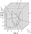
- the measuring fiber 7 is continuous and passes inside at least part of all the branches 31 of the support 3, forming a loop as visible on the figure. figure 5 .
- the portion of measuring fiber 7 entering the support 3 is opposite the portion of measuring fiber 7 exiting the support 3 in order to minimize the intrusive nature of the measuring device.
- the use of the optical fiber 8 makes it possible to multiplex the measurement fiber 7, the latter comprising a plurality of sensors (Bragg gratings, gauge strain gauge, Fabry-Pérot cavity, temperature probe, etc. placed along the measuring fiber 7.
- the measuring fiber 7 can pass inside all of the branches 31 of the plurality of branches 31 of the support 3.
- the support 3 comprises nine branches 31, six test bodies 5 and a temperature probe 35.
- the measuring device which has just been described can be set up and used as follows: A mold 100, comprising one or two recesses 101 on its wall 102, is partly filled with the material constituting the structure 1 ( figure 6a ). The material is in a liquid or viscous state.
- the support 3 is placed in the mold 100 on the surface of the material and oriented in the desired direction ( figure 6b ).
- the two parts 72 of the measuring fiber 7 are passed through one or two recesses 101 and respectively connected to the stimulation device 9 and to the acquisition system 10. Then, the support 3 is embedded in the material. constituting structure 1 in liquid form.
- the stimulation device 9 for example of the LASER type, emits an optical signal in the optical fiber 8.
- the optical signal is propagated along the optical fiber 8 and through the measuring fiber. 7, where it is modulated as a function of the deformations undergone by the measuring fiber 7.
- the modulated optical signal is transmitted along the optical fiber 8b to the acquisition system 10, where the signal is detected, then stored in the computer memory 12.
- the computer processes the information to determine a deformation in the structure 1 at the level of the support 3.
- This interrogation can be repeated over time, for example periodically.
- the computer is able to monitor a temporal evolution of the local endogenous deformation exerted from the younger age of the structure 1.
- the computer can be coupled to warning means in the event that a comparison of the deformations detected with a predetermined deformation was not deemed satisfactory.
Landscapes
- Physics & Mathematics (AREA)
- General Physics & Mathematics (AREA)
- Engineering & Computer Science (AREA)
- Aviation & Aerospace Engineering (AREA)
- Electromagnetism (AREA)
- Chemical & Material Sciences (AREA)
- Analytical Chemistry (AREA)
- Length Measuring Devices By Optical Means (AREA)
- Investigating Strength Of Materials By Application Of Mechanical Stress (AREA)
- Optical Transform (AREA)
Claims (15)
- Vorrichtung zum Messen von endogenen Deformationen einer Struktur (1) während des Übergangs der Struktur von einer flüssigen Phase in eine feste Phase, die Vorrichtung umfassend:- Probenkörper (5), von welchen jeder uniaxial ist und sich zwischen einem ersten Ende (5a) und einem zweiten Ende (5b) erstreckt, dazu eingerichtet, in der Struktur (1) eingebettet zu sein, und aus einem flexiblen homogenen Material mit bekannten mechanischen Eigenschaften bestehend,dadurch gekennzeichnet, dass die Vorrichtung umfasst:- einen Träger (3), welcher eine Mehrzahl von uniaxialen Zweigen (31) aufweist, wobei jeder der Probenkörper (5) einem der Zweige (31) des Trägers (3) zugeordnet ist,- eine Deformation-Messfaser (7), welche an dem Innenraum der Probenkörper (5) derart angebracht ist, dass Deformationen von jedem der Probenkörper (5) auf die Messfaser (7) übertragen werden, wobei die Messfaser (7) an dem Innenraum der Mehrzahl von Zweigen (31) derart befestigt ist, dass die durch die Mehrzahl von Zweigen (31) erfahrenen Deformationen auf die Messfaser (7) übertragen werden, und- ein System (9, 10, 11), welches mit der Messfaser (7) verbunden und dazu eingerichtet ist, Signale zu detektieren, welche von der Messfaser (7) stammen, welche Deformationen der Messfaser (7) repräsentieren, und die endogenen Deformationen ausgehend von wenigstens einem der detektierten Signale und den bekannten mechanischen Eigenschaften der Materialien des Probenkörpers (5) zu bestimmen,- wobei jeder Probenkörper (5) eine Steifigkeit aufweist, welche zwischen 2 und 5 Gigapascal beträgt, während die Zweige (31) jeweils eine Steifigkeit aufweisen, welche zwischen 2 und 5 Gigapascal beträgt.
- Vorrichtung nach Anspruch 1, wobei die Messfaser (7) eine optische Messfaser ist.
- Vorrichtung nach einem der Ansprüche 1 bis 2, wobei in jedem Probenkörper (5) ein Körper (51) vorgesehen ist, welcher von wenigstens einem Kanal (6) durchbrochen ist, welcher sich longitudinal zwischen dem ersten Ende (5a) und dem zweiten Ende (5b) des Probenkörpers (5) erstreckt, wobei wenigstens ein Teil der Messfaser (7) an dem Innenraum des Kanals angeklebt ist.
- Vorrichtung nach einem der Ansprüche 1 bis 2, wobei der Probenkörper (5) an wenigstens einem Teil der Messfaser (7) überformt ist.
- Vorrichtung nach einem der Ansprüche 1 bis 4, wobei der wenigstens eine Probenkörper (5) wenigstens einen Zapfen (55) umfasst, welche sich radial bezüglich des Probenkörpers zwischen einem ersten Ende (55a), welches mit dem Probenkörper verbunden ist, und einem freien zweiten Ende (55b) erstreckt.
- Vorrichtung nach einem der Ansprüche 1 bis 5, wobei die Messfaser (7) mit einem Dehnmessstreifen, einem Bragg-Gitter oder einem Fabry-Perot-Hohlraum ausgestattet ist.
- Vorrichtung nach einem der Ansprüche 1 bis 6, wobei die Vorrichtung wenigstens drei Probenkörper (5) umfasst, welche entlang dreier unterschiedlicher Richtungen angeordnet sind, einen ersten Probenkörper (5), welcher sich entlang einer ersten Richtung (X) erstreckt, einen zweiten Probenkörper (5), welcher sich entlang einer zweiten Richtung (Y) senkrecht zu der ersten Richtung (X) erstreckt, und einen dritten Probenkörper (5), welcher sich entlang einer dritten Richtung (Z) senkrecht zu der ersten Richtung (X) und zu der zweiten Richtung (Y) erstreckt.
- Vorrichtung nach Anspruch 7, wobei die Vorrichtung einen vierten Probenkörper (5) umfasst, welcher sich entlang einer vierten Richtung (XY) erstreckt, welche einer ersten Ebene (X;Y) angehört, welche die erste Richtung (X) und die zweite Richtung (Y) umfasst,und/oder einen fünften Probenkörper (5), welcher sich entlang einer fünften Richtung (YZ) erstreckt, welche einer zweiten Ebene (Y;Z) angehört, welche die zweite Richtung (Y) und die dritten Richtung (Z) umfasst,und/oder einen sechsten Probenkörper (5), welcher sich entlang einer sechsten Richtung (XZ) erstreckt, welche einer dritten Ebene (X;Z) angehört, welche die erste Richtung (X) und die dritte Richtung (Z) umfasst.
- Vorrichtung nach einem der Ansprüche 1 bis 8, wobei jeder unixiale Zweig (31) des Trägers (3) mit wenigstens einem anderen Zweig verbunden ist und die Zweige untereinander einen Innenraum von im Wesentlichen kubischer Form begrenzen,
und wobei die Messfaser (7) durchgehend ist und durch den Innenraum von jedem der Zweige (31) verläuft. - Vorrichtung nach dem Anspruch 7 und dem Anspruch 9, wobei wenigstens drei Zweige (31) aus den Zweigen (31) des Trägers (3) jeweils den ersten Probenkörper (5), den zweiten Probenkörper (5) und den dritten Probenkörper (5) umfassen.
- Vorrichtung nach dem Anspruch 8 und dem Anspruch 10, wobei wenigstens einer der Zweige (31) des Trägers (3) den vierten Probenkörper (5) umfasst, und/oder wobei wenigstens einer der Zweige (31) des Trägers den fünften Probenkörper (5) umfasst,und/oder wobei wenigstens einer der Zweige (31) des Trägers den sechsten Probenkörper (5) umfasst,wobei jeder der Zweige (31) des Trägers (3) maximal einen einzelnen Probenkörper (5) umfasst.
- Vorrichtung nach einem der Ansprüche 9 bis 11, wobei wenigstens ein Zweig aus den Zweigen (31) des Trägers (3) mit einer Temperatursonde (35) ausgestattet ist, welche von der Messfaser (7) getragen ist.
- Vorrichtung nach einem der Ansprüche 9 bis 12, wobei der Träger (3) wenigstens sieben Zweige (31) umfasst, und wobei die Messfaser (7), welche in dem Innenraum von jedem der Zweige verläuft, eine Schleife bildet.
- Mechanische Struktur (1), umfassend eine Vorrichtung zum Messen nach einem der Ansprüche 1 bis 13.
- Verfahren zum Messen von endogenen Deformationen einer Struktur (1) während eines Übergangs der Struktur von einer flüssigen Phase in eine feste Phase, wobei das Verfahren die folgenden Schritte umfasst:- Installieren einer Vorrichtung zum Messen nach einem der Ansprüche 1 bis 13,- Gießen der Struktur in flüssiger Phase um die Vorrichtung zum Messen herum,- Aufnehmen der Messungen durch das System (9, 10, 11) der Vorrichtung zum Messen während der Phase der Verfestigung der Struktur.
Applications Claiming Priority (2)
| Application Number | Priority Date | Filing Date | Title |
|---|---|---|---|
| FR1653907A FR3050818B1 (fr) | 2016-04-29 | 2016-04-29 | Dispositif de mesure de deformations endogenes |
| PCT/FR2017/050995 WO2017187090A1 (fr) | 2016-04-29 | 2017-04-27 | Dispositif de mesure de deformations endogenes |
Publications (2)
| Publication Number | Publication Date |
|---|---|
| EP3449208A1 EP3449208A1 (de) | 2019-03-06 |
| EP3449208B1 true EP3449208B1 (de) | 2021-10-06 |
Family
ID=56119670
Family Applications (1)
| Application Number | Title | Priority Date | Filing Date |
|---|---|---|---|
| EP17725315.0A Active EP3449208B1 (de) | 2016-04-29 | 2017-04-27 | Vorrichtung zur messung von endogenen deformationen |
Country Status (5)
| Country | Link |
|---|---|
| US (1) | US10634486B2 (de) |
| EP (1) | EP3449208B1 (de) |
| CN (1) | CN109154490B (de) |
| FR (1) | FR3050818B1 (de) |
| WO (1) | WO2017187090A1 (de) |
Families Citing this family (6)
| Publication number | Priority date | Publication date | Assignee | Title |
|---|---|---|---|---|
| WO2018220413A1 (en) * | 2017-06-02 | 2018-12-06 | Arcelormittal | Method for determining deformation, and associated equipment |
| US11662228B2 (en) * | 2018-06-22 | 2023-05-30 | The University Of Hong Kong | Real-time surface shape sensing for flexible structures |
| FR3124540B1 (fr) * | 2021-06-29 | 2023-07-28 | Centre Nat Rech Scient | Dispositif de mesure de déformations dans un trou de forage |
| FR3124539B1 (fr) * | 2021-06-29 | 2024-05-10 | Centre Nat Rech Scient | Dispositif de mesure de déformations dans un trou de forage |
| CN113758622B (zh) * | 2021-08-12 | 2024-08-16 | 华能澜沧江水电股份有限公司 | 扰动应力传感器的制作方法 |
| JP7629825B2 (ja) * | 2021-08-31 | 2025-02-14 | 太平洋セメント株式会社 | 応力モニタリングセンサ、センサ位置決め部材、および、応力モニタリング方法 |
Family Cites Families (7)
| Publication number | Priority date | Publication date | Assignee | Title |
|---|---|---|---|---|
| US5487307A (en) * | 1994-02-10 | 1996-01-30 | Kalman Floor Company, Inc. | Method and apparatus for testing concrete expansion |
| US6696974B1 (en) * | 2000-07-28 | 2004-02-24 | James I. Mathis | Cable device for detecting and monitoring rock and soil displacement |
| US6840114B2 (en) | 2003-05-19 | 2005-01-11 | Weatherford/Lamb, Inc. | Housing on the exterior of a well casing for optical fiber sensors |
| CN101087989B (zh) | 2004-10-15 | 2011-06-08 | 摩根研究股份有限公司 | 可嵌入的偏振光纤传感器及监测结构的方法 |
| BR112012020690B1 (pt) * | 2010-02-17 | 2020-02-04 | Pile Dynamics Inc | coluna de sensor e sistema para gerar uma matriz de temperatura e método de formação de um objeto estrutural |
| FR2996634B1 (fr) * | 2012-10-08 | 2014-12-12 | Electricite De France | Dispositif de mesure de deformations le long d'au moins une fibre optique, utilisation d'une fibre optique pour faire une mesure de deformations et procede de mesure de deformations |
| FR3003346B1 (fr) * | 2013-03-13 | 2016-01-29 | Univ Nantes | Capteur a fibre optique |
-
2016
- 2016-04-29 FR FR1653907A patent/FR3050818B1/fr not_active Expired - Fee Related
-
2017
- 2017-04-27 EP EP17725315.0A patent/EP3449208B1/de active Active
- 2017-04-27 CN CN201780031104.0A patent/CN109154490B/zh not_active Expired - Fee Related
- 2017-04-27 WO PCT/FR2017/050995 patent/WO2017187090A1/fr not_active Ceased
- 2017-04-27 US US16/097,453 patent/US10634486B2/en active Active
Also Published As
| Publication number | Publication date |
|---|---|
| EP3449208A1 (de) | 2019-03-06 |
| CN109154490B (zh) | 2020-11-06 |
| US10634486B2 (en) | 2020-04-28 |
| WO2017187090A1 (fr) | 2017-11-02 |
| US20190154435A1 (en) | 2019-05-23 |
| CN109154490A (zh) | 2019-01-04 |
| FR3050818B1 (fr) | 2020-02-21 |
| FR3050818A1 (fr) | 2017-11-03 |
Similar Documents
| Publication | Publication Date | Title |
|---|---|---|
| EP3449208B1 (de) | Vorrichtung zur messung von endogenen deformationen | |
| EP1723458B1 (de) | System zur verteilten messung von strukturbiegungen | |
| EP1377793B1 (de) | Bragg-gitter-dehnungsmesser mit langer basis und gespanntem optischen faser,sowie verfahren zu dessen herstellung | |
| Ferdinand | The evolution of optical fiber sensors technologies during the 35 last years and their applications in structure health monitoring | |
| CN101087989B (zh) | 可嵌入的偏振光纤传感器及监测结构的方法 | |
| EP2972072B1 (de) | Spannungsmessvorrichtung | |
| EP2861959B1 (de) | Vorrichtung zur messung der korrosion in einer metallstruktur oder einer struktur mit einer metallbewehrung, entsprechende verwendungen und verfahren | |
| WO2004099713A2 (fr) | Dispositif, systeme et procede de mesure de deformations mecaniques et/ou thermiques uniaxiales au moyen d'une fibre optique a reseau de bragg | |
| EP0022116B1 (de) | Gerät zum Messen der mechanischen Eigenschaften eines Körpers, besonders eines Bodens | |
| Nellen et al. | Optical fiber Bragg gratings for tunnel surveillance | |
| EP4377637B1 (de) | Verfahren zur nicht-invasiven messung der änderung des innendrucks eines rohres, messgerät und anordnung hierzu | |
| EP3299762B1 (de) | Instrumentiertes strukturelement aus beton | |
| Nawrot et al. | Mechanical strain-amplifying transducer for fiber Bragg grating sensors with applications in structural health monitoring | |
| EP1887316B1 (de) | Device for the measurement of deformations of a profile subject to one or more forces | |
| WO2025131752A1 (fr) | Dispositif de mesure de variations d'effort, de deformations mecaniques, de pressions hydrostatiques et de temperature, et procede de mesure associe | |
| EP1588124B1 (de) | Extensometer mit einem flexiblen messelement und bragggittern | |
| FR3157532A1 (fr) | Dispositif de mesure de variations d’effort, de déformations mécaniques, de pressions hydrostatiques et de température, et procédé de mesure associé | |
| Enckell | Structural health monitoring using modern sensor technology: long-term monitoring of the New Årsta Railway Bridge | |
| CN112378556A (zh) | 一种基于光纤传感的顶管管节内壁混凝土应力监测方法 | |
| CA2253625A1 (fr) | Procede et dispositifs de detection de flexion, et structure, telle que geotechnique ou de batiment, equipee d'un tel dispositif | |
| Inaudi et al. | Fiber optic sensors for structural control | |
| Choquet et al. | Advances in Fabry-Pérot fiber optic sensors and instruments for geotechnical monitoring | |
| Berthold III | Measurement of axial and bending strain in pipelines using Bragg grating sensors | |
| Delepine-Lesoille et al. | Multiplexed long-base flexible optical fiber extensometers and temperature bragg sensors interrogated by low-coherence interferometry | |
| Hofmann et al. | Lightning-safe diaphragm pressure gauge for geotechnical applications using a long-term reliable absolute EFPI sensor |
Legal Events
| Date | Code | Title | Description |
|---|---|---|---|
| STAA | Information on the status of an ep patent application or granted ep patent |
Free format text: STATUS: UNKNOWN |
|
| STAA | Information on the status of an ep patent application or granted ep patent |
Free format text: STATUS: THE INTERNATIONAL PUBLICATION HAS BEEN MADE |
|
| PUAI | Public reference made under article 153(3) epc to a published international application that has entered the european phase |
Free format text: ORIGINAL CODE: 0009012 |
|
| STAA | Information on the status of an ep patent application or granted ep patent |
Free format text: STATUS: REQUEST FOR EXAMINATION WAS MADE |
|
| 17P | Request for examination filed |
Effective date: 20181119 |
|
| AK | Designated contracting states |
Kind code of ref document: A1 Designated state(s): AL AT BE BG CH CY CZ DE DK EE ES FI FR GB GR HR HU IE IS IT LI LT LU LV MC MK MT NL NO PL PT RO RS SE SI SK SM TR |
|
| AX | Request for extension of the european patent |
Extension state: BA ME |
|
| DAV | Request for validation of the european patent (deleted) | ||
| DAX | Request for extension of the european patent (deleted) | ||
| GRAP | Despatch of communication of intention to grant a patent |
Free format text: ORIGINAL CODE: EPIDOSNIGR1 |
|
| STAA | Information on the status of an ep patent application or granted ep patent |
Free format text: STATUS: GRANT OF PATENT IS INTENDED |
|
| RIC1 | Information provided on ipc code assigned before grant |
Ipc: G01B 11/16 20060101AFI20210519BHEP Ipc: G01M 5/00 20060101ALI20210519BHEP Ipc: G01M 11/08 20060101ALI20210519BHEP |
|
| INTG | Intention to grant announced |
Effective date: 20210602 |
|
| GRAS | Grant fee paid |
Free format text: ORIGINAL CODE: EPIDOSNIGR3 |
|
| GRAA | (expected) grant |
Free format text: ORIGINAL CODE: 0009210 |
|
| STAA | Information on the status of an ep patent application or granted ep patent |
Free format text: STATUS: THE PATENT HAS BEEN GRANTED |
|
| AK | Designated contracting states |
Kind code of ref document: B1 Designated state(s): AL AT BE BG CH CY CZ DE DK EE ES FI FR GB GR HR HU IE IS IT LI LT LU LV MC MK MT NL NO PL PT RO RS SE SI SK SM TR |
|
| REG | Reference to a national code |
Ref country code: GB Ref legal event code: FG4D Free format text: NOT ENGLISH |
|
| REG | Reference to a national code |
Ref country code: CH Ref legal event code: EP Ref country code: AT Ref legal event code: REF Ref document number: 1436579 Country of ref document: AT Kind code of ref document: T Effective date: 20211015 |
|
| REG | Reference to a national code |
Ref country code: IE Ref legal event code: FG4D Free format text: LANGUAGE OF EP DOCUMENT: FRENCH |
|
| REG | Reference to a national code |
Ref country code: DE Ref legal event code: R096 Ref document number: 602017047121 Country of ref document: DE |
|
| REG | Reference to a national code |
Ref country code: LT Ref legal event code: MG9D |
|
| REG | Reference to a national code |
Ref country code: NL Ref legal event code: MP Effective date: 20211006 |
|
| REG | Reference to a national code |
Ref country code: AT Ref legal event code: MK05 Ref document number: 1436579 Country of ref document: AT Kind code of ref document: T Effective date: 20211006 |
|
| PG25 | Lapsed in a contracting state [announced via postgrant information from national office to epo] |
Ref country code: RS Free format text: LAPSE BECAUSE OF FAILURE TO SUBMIT A TRANSLATION OF THE DESCRIPTION OR TO PAY THE FEE WITHIN THE PRESCRIBED TIME-LIMIT Effective date: 20211006 Ref country code: LT Free format text: LAPSE BECAUSE OF FAILURE TO SUBMIT A TRANSLATION OF THE DESCRIPTION OR TO PAY THE FEE WITHIN THE PRESCRIBED TIME-LIMIT Effective date: 20211006 Ref country code: FI Free format text: LAPSE BECAUSE OF FAILURE TO SUBMIT A TRANSLATION OF THE DESCRIPTION OR TO PAY THE FEE WITHIN THE PRESCRIBED TIME-LIMIT Effective date: 20211006 Ref country code: BG Free format text: LAPSE BECAUSE OF FAILURE TO SUBMIT A TRANSLATION OF THE DESCRIPTION OR TO PAY THE FEE WITHIN THE PRESCRIBED TIME-LIMIT Effective date: 20220106 Ref country code: AT Free format text: LAPSE BECAUSE OF FAILURE TO SUBMIT A TRANSLATION OF THE DESCRIPTION OR TO PAY THE FEE WITHIN THE PRESCRIBED TIME-LIMIT Effective date: 20211006 |
|
| PG25 | Lapsed in a contracting state [announced via postgrant information from national office to epo] |
Ref country code: IS Free format text: LAPSE BECAUSE OF FAILURE TO SUBMIT A TRANSLATION OF THE DESCRIPTION OR TO PAY THE FEE WITHIN THE PRESCRIBED TIME-LIMIT Effective date: 20220206 Ref country code: SE Free format text: LAPSE BECAUSE OF FAILURE TO SUBMIT A TRANSLATION OF THE DESCRIPTION OR TO PAY THE FEE WITHIN THE PRESCRIBED TIME-LIMIT Effective date: 20211006 Ref country code: PT Free format text: LAPSE BECAUSE OF FAILURE TO SUBMIT A TRANSLATION OF THE DESCRIPTION OR TO PAY THE FEE WITHIN THE PRESCRIBED TIME-LIMIT Effective date: 20220207 Ref country code: PL Free format text: LAPSE BECAUSE OF FAILURE TO SUBMIT A TRANSLATION OF THE DESCRIPTION OR TO PAY THE FEE WITHIN THE PRESCRIBED TIME-LIMIT Effective date: 20211006 Ref country code: NO Free format text: LAPSE BECAUSE OF FAILURE TO SUBMIT A TRANSLATION OF THE DESCRIPTION OR TO PAY THE FEE WITHIN THE PRESCRIBED TIME-LIMIT Effective date: 20220106 Ref country code: NL Free format text: LAPSE BECAUSE OF FAILURE TO SUBMIT A TRANSLATION OF THE DESCRIPTION OR TO PAY THE FEE WITHIN THE PRESCRIBED TIME-LIMIT Effective date: 20211006 Ref country code: LV Free format text: LAPSE BECAUSE OF FAILURE TO SUBMIT A TRANSLATION OF THE DESCRIPTION OR TO PAY THE FEE WITHIN THE PRESCRIBED TIME-LIMIT Effective date: 20211006 Ref country code: HR Free format text: LAPSE BECAUSE OF FAILURE TO SUBMIT A TRANSLATION OF THE DESCRIPTION OR TO PAY THE FEE WITHIN THE PRESCRIBED TIME-LIMIT Effective date: 20211006 Ref country code: GR Free format text: LAPSE BECAUSE OF FAILURE TO SUBMIT A TRANSLATION OF THE DESCRIPTION OR TO PAY THE FEE WITHIN THE PRESCRIBED TIME-LIMIT Effective date: 20220107 Ref country code: ES Free format text: LAPSE BECAUSE OF FAILURE TO SUBMIT A TRANSLATION OF THE DESCRIPTION OR TO PAY THE FEE WITHIN THE PRESCRIBED TIME-LIMIT Effective date: 20211006 |
|
| REG | Reference to a national code |
Ref country code: DE Ref legal event code: R097 Ref document number: 602017047121 Country of ref document: DE |
|
| PG25 | Lapsed in a contracting state [announced via postgrant information from national office to epo] |
Ref country code: SM Free format text: LAPSE BECAUSE OF FAILURE TO SUBMIT A TRANSLATION OF THE DESCRIPTION OR TO PAY THE FEE WITHIN THE PRESCRIBED TIME-LIMIT Effective date: 20211006 Ref country code: SK Free format text: LAPSE BECAUSE OF FAILURE TO SUBMIT A TRANSLATION OF THE DESCRIPTION OR TO PAY THE FEE WITHIN THE PRESCRIBED TIME-LIMIT Effective date: 20211006 Ref country code: RO Free format text: LAPSE BECAUSE OF FAILURE TO SUBMIT A TRANSLATION OF THE DESCRIPTION OR TO PAY THE FEE WITHIN THE PRESCRIBED TIME-LIMIT Effective date: 20211006 Ref country code: EE Free format text: LAPSE BECAUSE OF FAILURE TO SUBMIT A TRANSLATION OF THE DESCRIPTION OR TO PAY THE FEE WITHIN THE PRESCRIBED TIME-LIMIT Effective date: 20211006 Ref country code: DK Free format text: LAPSE BECAUSE OF FAILURE TO SUBMIT A TRANSLATION OF THE DESCRIPTION OR TO PAY THE FEE WITHIN THE PRESCRIBED TIME-LIMIT Effective date: 20211006 Ref country code: CZ Free format text: LAPSE BECAUSE OF FAILURE TO SUBMIT A TRANSLATION OF THE DESCRIPTION OR TO PAY THE FEE WITHIN THE PRESCRIBED TIME-LIMIT Effective date: 20211006 |
|
| PLBE | No opposition filed within time limit |
Free format text: ORIGINAL CODE: 0009261 |
|
| STAA | Information on the status of an ep patent application or granted ep patent |
Free format text: STATUS: NO OPPOSITION FILED WITHIN TIME LIMIT |
|
| 26N | No opposition filed |
Effective date: 20220707 |
|
| PG25 | Lapsed in a contracting state [announced via postgrant information from national office to epo] |
Ref country code: AL Free format text: LAPSE BECAUSE OF FAILURE TO SUBMIT A TRANSLATION OF THE DESCRIPTION OR TO PAY THE FEE WITHIN THE PRESCRIBED TIME-LIMIT Effective date: 20211006 |
|
| PG25 | Lapsed in a contracting state [announced via postgrant information from national office to epo] |
Ref country code: SI Free format text: LAPSE BECAUSE OF FAILURE TO SUBMIT A TRANSLATION OF THE DESCRIPTION OR TO PAY THE FEE WITHIN THE PRESCRIBED TIME-LIMIT Effective date: 20211006 |
|
| REG | Reference to a national code |
Ref country code: CH Ref legal event code: PL |
|
| GBPC | Gb: european patent ceased through non-payment of renewal fee |
Effective date: 20220427 |
|
| REG | Reference to a national code |
Ref country code: BE Ref legal event code: MM Effective date: 20220430 |
|
| PG25 | Lapsed in a contracting state [announced via postgrant information from national office to epo] |
Ref country code: MC Free format text: LAPSE BECAUSE OF FAILURE TO SUBMIT A TRANSLATION OF THE DESCRIPTION OR TO PAY THE FEE WITHIN THE PRESCRIBED TIME-LIMIT Effective date: 20211006 Ref country code: LU Free format text: LAPSE BECAUSE OF NON-PAYMENT OF DUE FEES Effective date: 20220427 Ref country code: LI Free format text: LAPSE BECAUSE OF NON-PAYMENT OF DUE FEES Effective date: 20220430 Ref country code: GB Free format text: LAPSE BECAUSE OF NON-PAYMENT OF DUE FEES Effective date: 20220427 Ref country code: CH Free format text: LAPSE BECAUSE OF NON-PAYMENT OF DUE FEES Effective date: 20220430 |
|
| PG25 | Lapsed in a contracting state [announced via postgrant information from national office to epo] |
Ref country code: BE Free format text: LAPSE BECAUSE OF NON-PAYMENT OF DUE FEES Effective date: 20220430 |
|
| PG25 | Lapsed in a contracting state [announced via postgrant information from national office to epo] |
Ref country code: IE Free format text: LAPSE BECAUSE OF NON-PAYMENT OF DUE FEES Effective date: 20220427 |
|
| PG25 | Lapsed in a contracting state [announced via postgrant information from national office to epo] |
Ref country code: IT Free format text: LAPSE BECAUSE OF NON-PAYMENT OF DUE FEES Effective date: 20220427 |
|
| PG25 | Lapsed in a contracting state [announced via postgrant information from national office to epo] |
Ref country code: IT Free format text: LAPSE BECAUSE OF NON-PAYMENT OF DUE FEES Effective date: 20220427 |
|
| PGFP | Annual fee paid to national office [announced via postgrant information from national office to epo] |
Ref country code: IT Payment date: 20230411 Year of fee payment: 7 Ref country code: FR Payment date: 20230425 Year of fee payment: 7 Ref country code: DE Payment date: 20230412 Year of fee payment: 7 |
|
| PGRI | Patent reinstated in contracting state [announced from national office to epo] |
Ref country code: IT Effective date: 20220831 |
|
| PG25 | Lapsed in a contracting state [announced via postgrant information from national office to epo] |
Ref country code: HU Free format text: LAPSE BECAUSE OF FAILURE TO SUBMIT A TRANSLATION OF THE DESCRIPTION OR TO PAY THE FEE WITHIN THE PRESCRIBED TIME-LIMIT; INVALID AB INITIO Effective date: 20170427 |
|
| PG25 | Lapsed in a contracting state [announced via postgrant information from national office to epo] |
Ref country code: MK Free format text: LAPSE BECAUSE OF FAILURE TO SUBMIT A TRANSLATION OF THE DESCRIPTION OR TO PAY THE FEE WITHIN THE PRESCRIBED TIME-LIMIT Effective date: 20211006 Ref country code: CY Free format text: LAPSE BECAUSE OF FAILURE TO SUBMIT A TRANSLATION OF THE DESCRIPTION OR TO PAY THE FEE WITHIN THE PRESCRIBED TIME-LIMIT Effective date: 20211006 |
|
| PG25 | Lapsed in a contracting state [announced via postgrant information from national office to epo] |
Ref country code: TR Free format text: LAPSE BECAUSE OF FAILURE TO SUBMIT A TRANSLATION OF THE DESCRIPTION OR TO PAY THE FEE WITHIN THE PRESCRIBED TIME-LIMIT Effective date: 20211006 |
|
| PG25 | Lapsed in a contracting state [announced via postgrant information from national office to epo] |
Ref country code: MT Free format text: LAPSE BECAUSE OF FAILURE TO SUBMIT A TRANSLATION OF THE DESCRIPTION OR TO PAY THE FEE WITHIN THE PRESCRIBED TIME-LIMIT Effective date: 20211006 |
|
| REG | Reference to a national code |
Ref country code: DE Ref legal event code: R119 Ref document number: 602017047121 Country of ref document: DE |
|
| PG25 | Lapsed in a contracting state [announced via postgrant information from national office to epo] |
Ref country code: DE Free format text: LAPSE BECAUSE OF NON-PAYMENT OF DUE FEES Effective date: 20241105 |
|
| PG25 | Lapsed in a contracting state [announced via postgrant information from national office to epo] |
Ref country code: FR Free format text: LAPSE BECAUSE OF NON-PAYMENT OF DUE FEES Effective date: 20240430 |
|
| PG25 | Lapsed in a contracting state [announced via postgrant information from national office to epo] |
Ref country code: FR Free format text: LAPSE BECAUSE OF NON-PAYMENT OF DUE FEES Effective date: 20240430 Ref country code: DE Free format text: LAPSE BECAUSE OF NON-PAYMENT OF DUE FEES Effective date: 20241105 |
|
| REG | Reference to a national code |
Ref country code: DE Ref legal event code: R081 Ref document number: 602017047121 Country of ref document: DE Owner name: CENTRE NATIONAL DE LA RECHERCHE SCIENTIFIQUE, FR Free format text: FORMER OWNERS: CENTRE NATIONAL DE LA RECHERCHE SCIENTIFIQUE CNRS, PARIS, FR; UNIVERSITE DE NANTES, NANTES, FR Ref country code: DE Ref legal event code: R081 Ref document number: 602017047121 Country of ref document: DE Owner name: NANTES UNIVERSITE, FR Free format text: FORMER OWNERS: CENTRE NATIONAL DE LA RECHERCHE SCIENTIFIQUE CNRS, PARIS, FR; UNIVERSITE DE NANTES, NANTES, FR |