EP2972400B1 - Analyseur avec annonce de protocole lisible par machine - Google Patents
Analyseur avec annonce de protocole lisible par machine Download PDFInfo
- Publication number
- EP2972400B1 EP2972400B1 EP14716478.4A EP14716478A EP2972400B1 EP 2972400 B1 EP2972400 B1 EP 2972400B1 EP 14716478 A EP14716478 A EP 14716478A EP 2972400 B1 EP2972400 B1 EP 2972400B1
- Authority
- EP
- European Patent Office
- Prior art keywords
- scanner
- protocol
- detector
- signal
- data
- Prior art date
- Legal status (The legal status is an assumption and is not a legal conclusion. Google has not performed a legal analysis and makes no representation as to the accuracy of the status listed.)
- Active
Links
Images














Classifications
-
- G—PHYSICS
- G06—COMPUTING OR CALCULATING; COUNTING
- G06F—ELECTRIC DIGITAL DATA PROCESSING
- G06F16/00—Information retrieval; Database structures therefor; File system structures therefor
-
- G—PHYSICS
- G01—MEASURING; TESTING
- G01N—INVESTIGATING OR ANALYSING MATERIALS BY DETERMINING THEIR CHEMICAL OR PHYSICAL PROPERTIES
- G01N35/00—Automatic analysis not limited to methods or materials provided for in any single one of groups G01N1/00 - G01N33/00; Handling materials therefor
- G01N35/00584—Control arrangements for automatic analysers
-
- G—PHYSICS
- G01—MEASURING; TESTING
- G01N—INVESTIGATING OR ANALYSING MATERIALS BY DETERMINING THEIR CHEMICAL OR PHYSICAL PROPERTIES
- G01N35/00—Automatic analysis not limited to methods or materials provided for in any single one of groups G01N1/00 - G01N33/00; Handling materials therefor
- G01N35/00584—Control arrangements for automatic analysers
- G01N35/00722—Communications; Identification
- G01N35/00732—Identification of carriers, materials or components in automatic analysers
-
- G—PHYSICS
- G01—MEASURING; TESTING
- G01N—INVESTIGATING OR ANALYSING MATERIALS BY DETERMINING THEIR CHEMICAL OR PHYSICAL PROPERTIES
- G01N35/00—Automatic analysis not limited to methods or materials provided for in any single one of groups G01N1/00 - G01N33/00; Handling materials therefor
- G01N35/00584—Control arrangements for automatic analysers
- G01N35/00722—Communications; Identification
- G01N35/00732—Identification of carriers, materials or components in automatic analysers
- G01N2035/00821—Identification of carriers, materials or components in automatic analysers nature of coded information
- G01N2035/00851—Identification of carriers, materials or components in automatic analysers nature of coded information process control parameters
Definitions
- the present invention relates to systems and methods for performing biological assays.
- this application relates to automated analyzers and assay protocols for use with reagents.
- Bio assays using reagents and automated analyzers can involve several process steps for the user. Some assays, as well as the downstream data analysis that is performed after data acquisition, are more complex than others.
- Existing detection instrumentation uses complex software with a wide variety of variables and settings for the user to set prior to data acquisition. Furthermore, after data acquisition the user must analyze the data using conventional data analysis tools on their own. Currently, users must collect the raw data and plot the data themselves, which is sometimes done incorrectly or inefficiently.
- Previous systems collect data used to generate a standard curve and then store that data for use with future or subsequent experimental sample analysis. They also use a single data analysis method that is pre-defined prior to measuring experimental samples. Therefore, standards and experimental samples are analyzed in separate assays, in different operator runs, even on different days.
- a flexible diagnostic workstation comprises is equipped to read label information on well strips of loaded well plates and on loaded reagent kit holders, automatically perform the pre-analytical steps of an immuno-assay which consists of a sequence of operations in accordance with scheduled test requirements for each microwell, read the results according to either a standard singleplex ELISA or multiplex test format as indicated by the well strip label, and report the results.
- US 2008/0010520 discloses a biological sample processing apparatus having a central processing unit, a display in communication with the central processing unit and a selector for selecting a personality type of the apparatus, the selector being in communication with the central processing apparatus.
- the selection of a personality type prompts the central processing unit to cause the display to show a list of preprogrammed protocols for biological sample processing that correspond to the selected personality type.
- US 2009/0088336 discloses devices and systems, for use at the point of care, directed toward automatic detection of analytes in a bodily fluid.
- EP 2341351 discloses a test piece reading device and the test piece used therein.
- the test piece reading device comprises a housing, a monitor, a delivering device, an optical reader, a reaction signal reader and a control module.
- the test piece comprises at least one optically readable pattern which comprises identification information of the test piece.
- US 2009/0058617 discloses a method for setting up a system of a reagent chip analyzer. The method is adapted to modify parameters and testing conditions according to data of an authorization tag, so as to improve the adaptability range of the reagent chip analyzer for reagent chips of multiple specifications.
- US 2010/0001854 discloses an analyzer including: an information storage medium that is attached to a reagent vessel and is capable of communicating with an external device through radio waves of a predetermined frequency; a writing unit that writes history information that is generated as a reagent in the reagent vessel is used into the information storage medium; a reading unit that reads the history information from the information storage medium that is attached to the reagent vessel containing the reagent to be used; and a determining unit that determines whether a proper analysis is performable using the reagent in the reagent vessel, to which the information storage medium is attached, based on the history information read by the reading unit.
- the invention provides an analysis system according to claim 1.
- an analysis system utilizing a reagent for performing a biological assay on a sample.
- the reagent is associated with a machine-readable label.
- a scanner reads the machine-readable label and generates a scanner signal in response to reading the machine-readable label.
- a controller receives the scanner signal and selects a corresponding protocol from a plurality of protocols in response to at least the scanner signal.
- a memory stores the plurality of protocols for the automation of one or more assays performed on one or more samples.
- a detector generates a detector signal in response to the assay performed on the one or more samples. The detector signal is received by the controller and processed into a data set.
- a user input module facilitates user selection of assay protocol parameters.
- the user input module is in communication with the controller.
- a data processing module is in communication with the controller. The data processing module receives the data set and processes the data set according to the protocol.
- an analysis system including a detector, a scanner, a memory module, and a data processor is provided, along with a reagent including a machine-readable label.
- the machine readable label is scanned with the scanner and generates a scanner signal in response to reading the machine-readable label.
- a plurality of protocols for biological assays associated with the reagents is provided on the memory module.
- a protocol from the plurality of protocols is automatically selected in response to the scanner signal, where the protocol requires the reagent.
- a characteristic of the sample is detected with the detector.
- the detector generates a detector signal.
- a data set is collected from the detector signal. The data set is processed according to the protocol with the data processor.
- an analysis system 10 includes an analyzer, such as a luminometer 14.
- the analyzer could also be a fluorometer, thermocycler,, spectrometers, purification systems, or a multi-mode device (i.e., one that can measure luminescence, fluorescence, absorbance, and/or other characteristics) such as GloMax® Discover.
- the invention also has applications in biological sample processing, including purification and separation of biological constituents, such as with a Promega® Maxwell® device.
- the luminometer 14 is an easy-to-use, highly sensitive microplate luminometer with a broad dynamic range.
- the luminometer 14 may be used to perform a wide range of luminescent assays, including, for example, bioluminescent reporter, cell-based, and biochemical assays.
- the luminometer 14 includes a housing 18 surrounding an interior cavity 22.
- a sample tray 50 is configured to receive, for example, a microliter plate 52 such as a 96-well plate, a 384-well plate, or other suitable plates.
- the wells of the microtiter plate 52 may be pre-filled with a reagent by a user.
- reagent bottles are in fluid communication with the luminometer 14 (or other instrument type) such that a reagent may be distributed by the luminometer to the plate in the performance of an assay.
- An optical head 54 ( FIG. 2 ) includes a detector 58 ( FIG. 1 ), such as a luminescence detector.
- the luminescence detector 58 reads both glow- and flash-luminescent reactions in the wells of the 96-well plates.
- the luminescence detector detects a luminescence characteristic of a sample and generates a detector signal.
- the detector 58 may also measure absorbance, fluorescence, chemi-luminescence, electro-luminescence, UV-visible light or other sample characteristics.
- the detector signal is received by a controller 62 that is in communication with the detector 58.
- the controller 62 may be, for example, a microprocessor controller.
- the controller 62 is in communication with a memory module 66.
- a plurality of assay protocols are stored within the memory module 66, e.g. as firmware.
- the protocols include the sequence and timing required for the automation of one or more assays.
- the controller controls operation of the injector syringes and other mechanical aspects of the luminometer according to the assay protocols.
- the protocols also provide instructions for the collection, formatting and processing of the detector signals into a raw data set.
- the protocols also provide instructions for the final formatting, analysis, and plotting of the raw data.
- the controller 62 is in communication with a user interface 70, a scanner 74, and a data processor 78.
- the user interface 70, scanner 74, and data processor 78 may be stand-alone components in some embodiments of the invention. In other embodiments, they may be components of portable electronic device 82, such as a laptop computer, tablet computer (e.g., an IPAD), or a smart phone.
- Communication between the controller 62 and the interface module 70, the scanner module 74, and the data processing module 78 may be by wire or wireless communication. Wireless communication may be over a wireless local area network (e.g. a WIFI network), or a telecommunications network.
- the portable electronic device 82 or individual user 70, scanner 74 and data processor 78 may be wired to the controller 62 via an ETHERNET hub.
- the user interface 70, scanner 74, and data processor 78 may be integrated into the luminometer 14, such that the analyzer system 10 is a single unitary device.
- the user interface 70 is provided for viewing automatically selected assay, data analysis, and data output protocols. In some embodiments, the user interface 70 also provides for manual selection of protocols by the user.
- the user interface 70 includes a screen from which a user may view and select the protocols from the memory module 66.
- the screen may be, for example, an LCD or LED display and may include a touchscreen capability.
- the user interface 70 may be the touchscreen display of a tablet computer, or the combination of a keyboard and display of a laptop computer, or may be implemented using a series of buttons, e.g. adjacent to the screen.
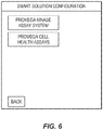
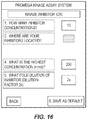
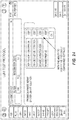
- FIGS. 5-9 , 13 , 16-24 , and 29-31 illustrate screen depictions of exemplary menus, protocol instructions, and user-selectable options that may be displayed on the user interface 70.
- the scanner 74 is provided for automatic selection of reagent protocols.
- the scanner 74 includes an optical bar code or matrix code reader.
- the scanner 74 is provided to read a machine readable media, such as a bar code, matrix code or RFID tag attached to a reagent box, bottle, or kit.
- FIG. 3 illustrates an example of a reagent box label 86 having a machine readable code such as a matrix code 90 (i.e., a two-dimensional code).
- the scanner 74 may also include an optical camera for reading bar codes or matrix codes, such as the camera of a tablet computer or other portable electronic device.
- the scanner may be an RFID scanner or other type of reader device.
- the user may manually enter a code (e.g. a combination of letters and/or numbers) to indicate which protocol to use.
- the scanner 74 Upon reading a machine-readable label that is associated with a reagent, the scanner 74 generates a scanner signal corresponding to the particular reagent. The scanner signal is communicated to the controller 62. Upon receiving the scanner signal, the controller 62 selects one or more corresponding protocols from the memory 66. The available protocol(s) are then displayed on the user interface 70 and provided to the data processor 78.
- the data processor 78 communicates with the controller 62 to receive raw data from the controller 62 to process, analyze and plot the data according to the protocol.
- the processed data including plots and statistical analysis, may be displayed on the user interface 70, and/or may be displayed on a separate display.
- the data processor utilizes Microsoft® Excel®, or other spreadsheet software, for data analysis and processing.
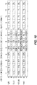
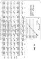
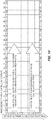
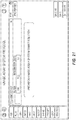
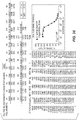
- FIGS. 10-12 , 14-15 , 17 , and 25-28 provide examples of processed data and plots from the data processor 78.
- a user interface 70, scanner 74 and data processor 78 allows for the integration of the workflow steps of a) automatically selecting the correct instrument protocol based on reagent kit machine-readable label, b) data acquisition and then c) automatic data analysis for the user.
- the user may initiate the protocol by scanning the machine-readable label from the reagent kit box, utilizing the scanner 74 or by making a manual selection on the user interface 74.
- the protocol will then guide the user through the setup process to begin data acquisition. Once the user begins the method and collects their data, the raw data from the controller 62 is then automatically analyzed and plotted graphically for the user in a pre-defined manner by the data processor 78.
- Simplified setup may involve fewer user-input variables or more complex setup may involve additional user-input variables.
- the pre-analyzed data from the data processor 78 may then be exported with the raw data for the user in a final report, where the user can further manipulate the data as desired.
- FIG. 4 provides an overview of one embodiment of the process of selecting a protocol, collecting data, and analyzing the data.
- a user first uses the scanner to scan a machine-readable label (e.g., the matrix code 90 of FIG. 3 ) that has been provided with the reagent.
- the analysis system 10 automatically selects an appropriate method and confirms all required dependencies. This bypasses the need for the user to select a protocol manually or to build their own protocol.
- the protocol After scanning the reagent kit, the protocol is initiated automatically.
- the protocol provides instructions for the user to load the samples and/or standards, and the ability for the user to select the type of standard curve they wish to perform, as well as the number of measurement points that are used to generate the standard curve.
- the user starts the selected method, and the selected method is performed to generate a raw data collection.
- the raw data may be expressed, for example, in relative light units (RLUs), relative fluorescent units (RFUs), absorbance, or other characteristics of the sample.
- the data is automatically plotted for the user so that the user does not have to do this following the data collection.
- Standards are measured at the same time as the experimental samples.
- the type of standard curve could be of a variety of types (e.g., linear fit, dose response, quadratic equation, etc.) as well as the number of standard points that are used to generate the standard curve (e.g., 2-12 points).
- the data processor 78 automatically selects a pre-defined template containing the desired curve fitting calculations and can export the data to a pre-defined location.
- the data processor 78 calculates average raw data for the section of the template containing standards with known concentration.
- the data processor 78 also performs regression analysis using a pre-defined regression model, incorporating the average readings for all standards, and plots the trend line.
- the data processor 78 calculates regression coefficients, a coefficient of determination R2, a standard deviation SD, and other necessary statistical data. Using calculated regression coefficients, the data processor determines and displays concentration for unknowns in a microplate.
- Workflow begins when a user scans the barcode of GloMax® CellTiter-Glo® luminescence test kit with the scanner 74.
- the raw data is collected and a linear calculation is applied.
- An average of plate wells A8, B8, and C8 is taken. These are the background controls.
- the Average Background from each well (A1 to A7, B1 to B7 and C1 to C7) is subtracted.
- the background-subtracted triplicate samples from A1,B1,C1; A2,B2,C2; etc. through column 7 are averaged.
- a plot is made of the Average RLU minus Background values versus the ATP concentration, and graph labels are added.
- An R2 value is calculated from the linear fit.
- the raw data is collected and a linear calculation is applied.
- an average of wells A6, B6, and C6 is taken as background controls.
- the Average Background is then subtracted from each well (A1 to A5, B1 to B5, and C1 to C5).
- the background-subtracted triplicate samples from A1,B1,C1; A2,B2,C2; etc. through column 5 are averaged.
- Example 3 Bovine Serum Albumin Assay.
- Workflow begins when a user scans the barcode of GloMax® Absorbance Test Kit with the scanner.
- a window is displayed on the screen of the user interface 70, with the following instructions for the user:
- the raw data is then collected and a linear calculation of the data is applied.
- an average of A8, B8, and C8 is calculated and used as the background controls.
- the Average Background is subtracted from each well (A1 to A5, B1 to B7, and C1 to C7).
- the background-subtracted triplicate samples from A1,B1,C1; A2,B2,C2; etc. through column 7 are averaged.
- a plot is made of the Average Absorbance minus Background values versus the protein concentration and an R2 value is calculated from the linear fit.
- Workflow begins when a user scans the barcode of a GloMax® Nano-Glo® Luminescence Kit.
- a window is displayed on the user interface, with the following instructions for the user:
- the raw data is then collected and a linear calculation of the data is applied.
- wells A8, B8, and C8 are averaged and used as the background controls.
- the Average Background is subtracted from each well (A1 to A5, B1 to B7, and C1 to C7).
- the background subtracted triplicate samples from A1,B1,C1; A2,B2,C2; etc. through column 7 are then averaged.
Landscapes
- General Physics & Mathematics (AREA)
- Engineering & Computer Science (AREA)
- Physics & Mathematics (AREA)
- Immunology (AREA)
- Health & Medical Sciences (AREA)
- Biochemistry (AREA)
- General Health & Medical Sciences (AREA)
- Chemical & Material Sciences (AREA)
- Life Sciences & Earth Sciences (AREA)
- Pathology (AREA)
- Analytical Chemistry (AREA)
- Theoretical Computer Science (AREA)
- Databases & Information Systems (AREA)
- General Engineering & Computer Science (AREA)
- Data Mining & Analysis (AREA)
- Investigating, Analyzing Materials By Fluorescence Or Luminescence (AREA)
- Automatic Analysis And Handling Materials Therefor (AREA)
- Investigating Or Analysing Materials By The Use Of Chemical Reactions (AREA)
- Investigating Or Analysing Biological Materials (AREA)
Claims (15)
- Système d'analyse (10) utilisant un réactif pour réaliser un dosage biologique sur un échantillon, où le réactif est associé à un label lisible par machine (86), le système comprenant:un scanneur (74) pour lire le label lisible par machine (86), le scanneur générant un signal de scanneur en réponse à la lecture du label lisible par machine et communiquant le signal de scanneur à un dispositif de commande (62) ;une mémoire (66) stockant une pluralité de protocoles pour l'automatisation d'un ou de plusieurs dosages réalisés sur un ou plusieurs échantillons ;un détecteur (58) générant un signal de détecteur en réponse à l'échantillon ;le dispositif de commande (62) recevant le signal de scanneur et sélectionnant un protocole correspondant parmi la pluralité de protocoles issus de la mémoire (66) en réponse au signal de scanneur et le dispositif de commande recevant le signal de détecteur et traitant le signal de détecteur dans un ensemble de données ;un module d'entrée utilisateur (70) pour une sélection par l'utilisateur de paramètres de protocole de dosage, le module d'entrée utilisateur étant en communication avec le dispositif de commande (62) ; etcaractérisé en ce que :le protocole comporte également des instructions pour traiter l'ensemble de données et en ce qu'il comprend en outre un module de traitement de données (78) en communication avec le dispositif de commande (62), le module de traitement de données recevant l'ensemble de données et traitant l'ensemble de données selon le protocole, réalisant des calculs d'ajustement de courbe en réponse au signal de scanneur et générant un tracé à partir de l'ensemble de données en réponse au signal de scanneur.
- Système d'analyse (10) selon la revendication 1, dans lequel le scanneur (74), le module d'entrée utilisateur (70) et le module de traitement de données (78) sont des composants d'un dispositif électronique portable (82).
- Système d'analyse (10) selon la revendication 2, dans lequel le dispositif électronique portable (82) est une tablette informatique ou un ordinateur portable.
- Système d'analyse (10) selon la revendication 1, dans lequel le label lisible par machine (86) comporte un code-barres, et dans lequel le scanneur (74) est configuré pour lire un code-barres.
- Système d'analyse (10) selon la revendication 1, dans lequel le label lisible par machine (86) comprend un code matriciel et dans lequel le scanneur (74) est configuré pour lire le code matriciel.
- Système d'analyse (10) selon la revendication 1, dans lequel le label lisible par machine (86) comporte une étiquette RFID et dans lequel le scanneur (74) est un lecteur RFID.
- Système d'analyse (10) selon la revendication 1, dans lequel le module de traitement de données (78) détermine un coefficient de valeur de détermination à partir de l'ensemble de données en réponse au signal de scanneur.
- Système d'analyse (10) selon la revendication 1, dans lequel le détecteur (58) comporte un détecteur de luminescence, de fluorescence, d'absorbance, de lumière UV-visible ou multimode.
- Système d'analyse (10) selon la revendication 1, dans lequel le module d'entrée utilisateur (70) comporte une portion d'affichage, la portion d'affichage affichant des paramètres de protocole sélectionnables par utilisateur en réponse au signal de scanneur.
- Procédé de réalisation d'un dosage biologique sur un échantillon, comprenant :la fourniture d'un système d'analyse comportant un détecteur, un scanneur, un module de mémoire et un processeur de données ;la fourniture d'un réactif comportant un label lisible par machine qui contient des informations pour la sélection d'un protocole ;le balayage du label lisible par machine avec le scanneur et la génération d'un signal de scanneur en réponse à la lecture du label lisible par machine ;la fourniture d'une pluralité de protocoles pour des dosages biologiques sur le module de mémoire ;la sélection automatique d'un protocole de la pluralité de protocoles en réponse au signal de scanneur, le protocole requérant le réactif ;la détection d'une caractéristique de l'échantillon avec le détecteur, le détecteur générant un signal de détecteur ;la collecte d'un ensemble de données à partir du signal de détecteur ; etcaractérisé en ce que le protocole comporte également des instructions pour traiter l'ensemble de données et en outre parle traitement de l'ensemble de données selon le protocole avec le processeur de données, le traitement comportant la réalisation de calculs d'ajustement de courbe en réponse au signal de scanneur ; et le tracé de l'ensemble de données selon le protocole.
- Procédé selon la revendication 10, comprenant en outre le calcul d'un coefficient de détermination à partir de l'ensemble de données.
- Procédé selon la revendication 10, dans lequel l'acte de balayer le label lisible par machine comporte le balayage d'un code-barres, le balayage d'un code matriciel ou le balayage d'une étiquette RFID.
- Procédé selon la revendication 10, dans lequel l'acte de détecter une caractéristique de l'échantillon avec le détecteur comporte la détection d'au moins l'une parmi une luminescence, une fluorescence, une absorbance ou une lumière UV-visible de l'échantillon.
- Procédé selon la revendication 10, comprenant en outre la fourniture d'un module d'entrée utilisateur pour la sélection par l'utilisateur de paramètres de protocole.
- Procédé selon la revendication 10, comprenant en outre l'affichage de paramètres de protocole sur l'organe d'entrée utilisateur.
Applications Claiming Priority (2)
| Application Number | Priority Date | Filing Date | Title |
|---|---|---|---|
| US13/792,557 US20140252079A1 (en) | 2013-03-11 | 2013-03-11 | Analyzer with machine readable protocol prompting |
| PCT/US2014/022577 WO2014164489A1 (fr) | 2013-03-11 | 2014-03-10 | Analyseur avec annonce de protocole lisible par machine |
Publications (2)
| Publication Number | Publication Date |
|---|---|
| EP2972400A1 EP2972400A1 (fr) | 2016-01-20 |
| EP2972400B1 true EP2972400B1 (fr) | 2017-09-13 |
Family
ID=50473786
Family Applications (1)
| Application Number | Title | Priority Date | Filing Date |
|---|---|---|---|
| EP14716478.4A Active EP2972400B1 (fr) | 2013-03-11 | 2014-03-10 | Analyseur avec annonce de protocole lisible par machine |
Country Status (4)
| Country | Link |
|---|---|
| US (1) | US20140252079A1 (fr) |
| EP (1) | EP2972400B1 (fr) |
| JP (1) | JP6324485B2 (fr) |
| WO (1) | WO2014164489A1 (fr) |
Families Citing this family (12)
| Publication number | Priority date | Publication date | Assignee | Title |
|---|---|---|---|---|
| AU2013334189B2 (en) | 2012-10-24 | 2018-08-02 | Genmark Diagnostics, Inc. | Integrated multiplex target analysis |
| US20140322706A1 (en) | 2012-10-24 | 2014-10-30 | Jon Faiz Kayyem | Integrated multipelx target analysis |
| JP6351702B2 (ja) | 2013-03-15 | 2018-07-04 | ジェンマーク ダイアグノスティクス, インコーポレイテッド | 変形可能流体容器を操作するためのシステム、方法、および装置 |
| US20140368443A1 (en) * | 2013-06-14 | 2014-12-18 | Agilent Technologies, Inc. | System for Automating Laboratory Experiments |
| US9498778B2 (en) | 2014-11-11 | 2016-11-22 | Genmark Diagnostics, Inc. | Instrument for processing cartridge for performing assays in a closed sample preparation and reaction system |
| USD881409S1 (en) | 2013-10-24 | 2020-04-14 | Genmark Diagnostics, Inc. | Biochip cartridge |
| US11300579B2 (en) | 2015-07-23 | 2022-04-12 | Meso Scale Technologies, Llc. | Integrated consumable data management system and platform |
| EP3514549B1 (fr) * | 2016-09-16 | 2024-10-09 | Hitachi High-Tech Corporation | Analyseur automatisé et système d'analyse automatisé |
| US11300578B2 (en) | 2016-09-19 | 2022-04-12 | Roche Molecular Systems, Inc. | Instrument for processing cartridge for performing assays in a closed sample preparation and reaction system |
| EP4130748A4 (fr) * | 2020-03-23 | 2024-03-27 | Hitachi High-Tech Corporation | Système d'analyse automatique |
| WO2021252923A1 (fr) | 2020-06-12 | 2021-12-16 | Genmark Diagnostics, Inc. | Systèmes et procédés d'évaluation de baies sur des dispositifs de diagnostic |
| EP4435691A1 (fr) * | 2023-03-21 | 2024-09-25 | Netzsch Gerätebau GmbH | Procédé de commande d'un dispositif de mesure et dispositif de mesure |
Family Cites Families (12)
| Publication number | Priority date | Publication date | Assignee | Title |
|---|---|---|---|---|
| CA2096198A1 (fr) * | 1992-06-26 | 1993-12-27 | Christopher J. Macko | Analyseur clinique automatise avec controle de la temperature |
| WO2001068259A1 (fr) * | 2000-03-16 | 2001-09-20 | Biogenex Laboratories | Dispositif automatique de traitement de specimen presentant une caracteristique de detection de liquide |
| EP1673608A4 (fr) * | 2003-09-29 | 2008-05-07 | Vision Biosystems Ltd | Systeme et procede de traitement de specimens de tissu histologique |
| WO2007149311A2 (fr) * | 2006-06-16 | 2007-12-27 | Promega Corporation | Appareil de traitement d'échantillons biologiques qui sélectionne le type de personnalité de l'appareil |
| JP2008224384A (ja) * | 2007-03-12 | 2008-09-25 | Olympus Corp | 分析装置および分析方法 |
| TW200912309A (en) * | 2007-09-04 | 2009-03-16 | Kaiwood Technology Co Ltd | System configuration method of color indicating chip analyzer |
| CA3138078C (fr) * | 2007-10-02 | 2024-02-13 | Labrador Diagnostics Llc | Dispositifs modulaires a utiliser sur place et leurs utilisations |
| WO2010011931A2 (fr) * | 2008-07-24 | 2010-01-28 | Immco Diagnostics | Station de travail diagnostique automatisée |
| EP2341351A4 (fr) * | 2008-10-13 | 2013-03-13 | Actherm Inc | Dispositif de lecture de bandelette réactive et bandelette réactive associée |
| US8035485B2 (en) * | 2008-11-20 | 2011-10-11 | Abbott Laboratories | System for tracking vessels in automated laboratory analyzers by radio frequency identification |
| US20140335505A1 (en) * | 2011-09-25 | 2014-11-13 | Theranos, Inc. | Systems and methods for collecting and transmitting assay results |
| US9176154B2 (en) * | 2012-12-12 | 2015-11-03 | Bio-Rad Laboratories, Inc. | Calibration process and system |
-
2013
- 2013-03-11 US US13/792,557 patent/US20140252079A1/en not_active Abandoned
-
2014
- 2014-03-10 JP JP2016501006A patent/JP6324485B2/ja active Active
- 2014-03-10 WO PCT/US2014/022577 patent/WO2014164489A1/fr not_active Ceased
- 2014-03-10 EP EP14716478.4A patent/EP2972400B1/fr active Active
Non-Patent Citations (1)
| Title |
|---|
| None * |
Also Published As
| Publication number | Publication date |
|---|---|
| EP2972400A1 (fr) | 2016-01-20 |
| WO2014164489A1 (fr) | 2014-10-09 |
| US20140252079A1 (en) | 2014-09-11 |
| JP6324485B2 (ja) | 2018-05-16 |
| JP2016516994A (ja) | 2016-06-09 |
Similar Documents
| Publication | Publication Date | Title |
|---|---|---|
| EP2972400B1 (fr) | Analyseur avec annonce de protocole lisible par machine | |
| EP3570040B1 (fr) | Procédé d'analyse d'un échantillon biologique | |
| US20210208082A1 (en) | Method, apparatus and system for detecting and determining compromised reagent pads by quantifying color changes induced by exposure to a hostile environment | |
| US20080240983A1 (en) | Modular assay reader system and apparatus | |
| JP2525063B2 (ja) | 自動分析方法 | |
| CN102539661B (zh) | 样本分析装置 | |
| JP2022519647A (ja) | 診断検査を容易にするための、患者idおよび試料idのワークフローの方法および装置 | |
| US20170098137A1 (en) | Method, apparatus and system for detecting and determining compromised reagent pads by quantifying color changes induced by exposure to a hostile environment | |
| CN101135692A (zh) | 自动分析装置 | |
| EP2321649A2 (fr) | Station de travail diagnostique automatisée | |
| US9121839B2 (en) | Analyzing system, analyzing apparatus, container, analyzing method, program, and recording medium | |
| JP2012108010A (ja) | 自動分析装置 | |
| WO2013042431A1 (fr) | Dispositif d'analyse automatique | |
| KR20180108535A (ko) | 측정장치 및 측정방법 | |
| JP2016090536A (ja) | 自動分析装置及び動作指定方法 | |
| CN114646767A (zh) | 实验室分析仪 | |
| JP5002241B2 (ja) | 自動分析装置、自動分析装置の測定方法、及び検査情報システム | |
| EP4502614A1 (fr) | Système de traitement d'échantillon | |
| US20250246264A1 (en) | Method of guiding at least two detailed performance experiments required for developing reagent for detecting target nucleic acid molecule, and organizing an experiment result documentation | |
| EP4040161B1 (fr) | Procédé de sélection de condition de perçage | |
| US20230001411A1 (en) | Portable device for in situ genetic analyses | |
| WO2024101274A1 (fr) | Dispositif d'analyse d'échantillon d'analyte, et procédé de génération de courbe d'étalonnage | |
| EP4006548A1 (fr) | Système d'automatisation de tests multi-transferts | |
| CN119224333A (zh) | 样本分析仪及样本调度方法 | |
| CN119452099A (zh) | 基因检查方法及基因检查装置 |
Legal Events
| Date | Code | Title | Description |
|---|---|---|---|
| PUAI | Public reference made under article 153(3) epc to a published international application that has entered the european phase |
Free format text: ORIGINAL CODE: 0009012 |
|
| 17P | Request for examination filed |
Effective date: 20150908 |
|
| AK | Designated contracting states |
Kind code of ref document: A1 Designated state(s): AL AT BE BG CH CY CZ DE DK EE ES FI FR GB GR HR HU IE IS IT LI LT LU LV MC MK MT NL NO PL PT RO RS SE SI SK SM TR |
|
| AX | Request for extension of the european patent |
Extension state: BA ME |
|
| DAX | Request for extension of the european patent (deleted) | ||
| GRAP | Despatch of communication of intention to grant a patent |
Free format text: ORIGINAL CODE: EPIDOSNIGR1 |
|
| STAA | Information on the status of an ep patent application or granted ep patent |
Free format text: STATUS: GRANT OF PATENT IS INTENDED |
|
| INTG | Intention to grant announced |
Effective date: 20170407 |
|
| GRAS | Grant fee paid |
Free format text: ORIGINAL CODE: EPIDOSNIGR3 |
|
| GRAA | (expected) grant |
Free format text: ORIGINAL CODE: 0009210 |
|
| STAA | Information on the status of an ep patent application or granted ep patent |
Free format text: STATUS: THE PATENT HAS BEEN GRANTED |
|
| AK | Designated contracting states |
Kind code of ref document: B1 Designated state(s): AL AT BE BG CH CY CZ DE DK EE ES FI FR GB GR HR HU IE IS IT LI LT LU LV MC MK MT NL NO PL PT RO RS SE SI SK SM TR |
|
| REG | Reference to a national code |
Ref country code: GB Ref legal event code: FG4D |
|
| REG | Reference to a national code |
Ref country code: CH Ref legal event code: EP |
|
| REG | Reference to a national code |
Ref country code: IE Ref legal event code: FG4D |
|
| REG | Reference to a national code |
Ref country code: AT Ref legal event code: REF Ref document number: 928677 Country of ref document: AT Kind code of ref document: T Effective date: 20171015 |
|
| REG | Reference to a national code |
Ref country code: DE Ref legal event code: R096 Ref document number: 602014014535 Country of ref document: DE |
|
| REG | Reference to a national code |
Ref country code: NL Ref legal event code: MP Effective date: 20170913 |
|
| REG | Reference to a national code |
Ref country code: LT Ref legal event code: MG4D |
|
| PG25 | Lapsed in a contracting state [announced via postgrant information from national office to epo] |
Ref country code: NO Free format text: LAPSE BECAUSE OF FAILURE TO SUBMIT A TRANSLATION OF THE DESCRIPTION OR TO PAY THE FEE WITHIN THE PRESCRIBED TIME-LIMIT Effective date: 20171213 Ref country code: HR Free format text: LAPSE BECAUSE OF FAILURE TO SUBMIT A TRANSLATION OF THE DESCRIPTION OR TO PAY THE FEE WITHIN THE PRESCRIBED TIME-LIMIT Effective date: 20170913 Ref country code: LT Free format text: LAPSE BECAUSE OF FAILURE TO SUBMIT A TRANSLATION OF THE DESCRIPTION OR TO PAY THE FEE WITHIN THE PRESCRIBED TIME-LIMIT Effective date: 20170913 Ref country code: FI Free format text: LAPSE BECAUSE OF FAILURE TO SUBMIT A TRANSLATION OF THE DESCRIPTION OR TO PAY THE FEE WITHIN THE PRESCRIBED TIME-LIMIT Effective date: 20170913 Ref country code: SE Free format text: LAPSE BECAUSE OF FAILURE TO SUBMIT A TRANSLATION OF THE DESCRIPTION OR TO PAY THE FEE WITHIN THE PRESCRIBED TIME-LIMIT Effective date: 20170913 |
|
| REG | Reference to a national code |
Ref country code: AT Ref legal event code: MK05 Ref document number: 928677 Country of ref document: AT Kind code of ref document: T Effective date: 20170913 |
|
| PG25 | Lapsed in a contracting state [announced via postgrant information from national office to epo] |
Ref country code: GR Free format text: LAPSE BECAUSE OF FAILURE TO SUBMIT A TRANSLATION OF THE DESCRIPTION OR TO PAY THE FEE WITHIN THE PRESCRIBED TIME-LIMIT Effective date: 20171214 Ref country code: LV Free format text: LAPSE BECAUSE OF FAILURE TO SUBMIT A TRANSLATION OF THE DESCRIPTION OR TO PAY THE FEE WITHIN THE PRESCRIBED TIME-LIMIT Effective date: 20170913 Ref country code: BG Free format text: LAPSE BECAUSE OF FAILURE TO SUBMIT A TRANSLATION OF THE DESCRIPTION OR TO PAY THE FEE WITHIN THE PRESCRIBED TIME-LIMIT Effective date: 20171213 Ref country code: RS Free format text: LAPSE BECAUSE OF FAILURE TO SUBMIT A TRANSLATION OF THE DESCRIPTION OR TO PAY THE FEE WITHIN THE PRESCRIBED TIME-LIMIT Effective date: 20170913 Ref country code: ES Free format text: LAPSE BECAUSE OF FAILURE TO SUBMIT A TRANSLATION OF THE DESCRIPTION OR TO PAY THE FEE WITHIN THE PRESCRIBED TIME-LIMIT Effective date: 20170913 |
|
| REG | Reference to a national code |
Ref country code: FR Ref legal event code: PLFP Year of fee payment: 5 |
|
| PG25 | Lapsed in a contracting state [announced via postgrant information from national office to epo] |
Ref country code: NL Free format text: LAPSE BECAUSE OF FAILURE TO SUBMIT A TRANSLATION OF THE DESCRIPTION OR TO PAY THE FEE WITHIN THE PRESCRIBED TIME-LIMIT Effective date: 20170913 |
|
| PG25 | Lapsed in a contracting state [announced via postgrant information from national office to epo] |
Ref country code: RO Free format text: LAPSE BECAUSE OF FAILURE TO SUBMIT A TRANSLATION OF THE DESCRIPTION OR TO PAY THE FEE WITHIN THE PRESCRIBED TIME-LIMIT Effective date: 20170913 Ref country code: CZ Free format text: LAPSE BECAUSE OF FAILURE TO SUBMIT A TRANSLATION OF THE DESCRIPTION OR TO PAY THE FEE WITHIN THE PRESCRIBED TIME-LIMIT Effective date: 20170913 Ref country code: PL Free format text: LAPSE BECAUSE OF FAILURE TO SUBMIT A TRANSLATION OF THE DESCRIPTION OR TO PAY THE FEE WITHIN THE PRESCRIBED TIME-LIMIT Effective date: 20170913 |
|
| PG25 | Lapsed in a contracting state [announced via postgrant information from national office to epo] |
Ref country code: SK Free format text: LAPSE BECAUSE OF FAILURE TO SUBMIT A TRANSLATION OF THE DESCRIPTION OR TO PAY THE FEE WITHIN THE PRESCRIBED TIME-LIMIT Effective date: 20170913 Ref country code: IS Free format text: LAPSE BECAUSE OF FAILURE TO SUBMIT A TRANSLATION OF THE DESCRIPTION OR TO PAY THE FEE WITHIN THE PRESCRIBED TIME-LIMIT Effective date: 20180113 Ref country code: SM Free format text: LAPSE BECAUSE OF FAILURE TO SUBMIT A TRANSLATION OF THE DESCRIPTION OR TO PAY THE FEE WITHIN THE PRESCRIBED TIME-LIMIT Effective date: 20170913 Ref country code: AT Free format text: LAPSE BECAUSE OF FAILURE TO SUBMIT A TRANSLATION OF THE DESCRIPTION OR TO PAY THE FEE WITHIN THE PRESCRIBED TIME-LIMIT Effective date: 20170913 Ref country code: IT Free format text: LAPSE BECAUSE OF FAILURE TO SUBMIT A TRANSLATION OF THE DESCRIPTION OR TO PAY THE FEE WITHIN THE PRESCRIBED TIME-LIMIT Effective date: 20170913 Ref country code: EE Free format text: LAPSE BECAUSE OF FAILURE TO SUBMIT A TRANSLATION OF THE DESCRIPTION OR TO PAY THE FEE WITHIN THE PRESCRIBED TIME-LIMIT Effective date: 20170913 |
|
| REG | Reference to a national code |
Ref country code: DE Ref legal event code: R097 Ref document number: 602014014535 Country of ref document: DE |
|
| PLBE | No opposition filed within time limit |
Free format text: ORIGINAL CODE: 0009261 |
|
| STAA | Information on the status of an ep patent application or granted ep patent |
Free format text: STATUS: NO OPPOSITION FILED WITHIN TIME LIMIT |
|
| PG25 | Lapsed in a contracting state [announced via postgrant information from national office to epo] |
Ref country code: DK Free format text: LAPSE BECAUSE OF FAILURE TO SUBMIT A TRANSLATION OF THE DESCRIPTION OR TO PAY THE FEE WITHIN THE PRESCRIBED TIME-LIMIT Effective date: 20170913 |
|
| 26N | No opposition filed |
Effective date: 20180614 |
|
| REG | Reference to a national code |
Ref country code: CH Ref legal event code: PL |
|
| PG25 | Lapsed in a contracting state [announced via postgrant information from national office to epo] |
Ref country code: SI Free format text: LAPSE BECAUSE OF FAILURE TO SUBMIT A TRANSLATION OF THE DESCRIPTION OR TO PAY THE FEE WITHIN THE PRESCRIBED TIME-LIMIT Effective date: 20170913 Ref country code: MC Free format text: LAPSE BECAUSE OF FAILURE TO SUBMIT A TRANSLATION OF THE DESCRIPTION OR TO PAY THE FEE WITHIN THE PRESCRIBED TIME-LIMIT Effective date: 20170913 |
|
| REG | Reference to a national code |
Ref country code: BE Ref legal event code: MM Effective date: 20180331 |
|
| REG | Reference to a national code |
Ref country code: IE Ref legal event code: MM4A |
|
| PG25 | Lapsed in a contracting state [announced via postgrant information from national office to epo] |
Ref country code: LU Free format text: LAPSE BECAUSE OF NON-PAYMENT OF DUE FEES Effective date: 20180310 |
|
| PG25 | Lapsed in a contracting state [announced via postgrant information from national office to epo] |
Ref country code: IE Free format text: LAPSE BECAUSE OF NON-PAYMENT OF DUE FEES Effective date: 20180310 |
|
| PG25 | Lapsed in a contracting state [announced via postgrant information from national office to epo] |
Ref country code: CH Free format text: LAPSE BECAUSE OF NON-PAYMENT OF DUE FEES Effective date: 20180331 Ref country code: LI Free format text: LAPSE BECAUSE OF NON-PAYMENT OF DUE FEES Effective date: 20180331 Ref country code: BE Free format text: LAPSE BECAUSE OF NON-PAYMENT OF DUE FEES Effective date: 20180331 |
|
| PG25 | Lapsed in a contracting state [announced via postgrant information from national office to epo] |
Ref country code: MT Free format text: LAPSE BECAUSE OF NON-PAYMENT OF DUE FEES Effective date: 20180310 |
|
| PG25 | Lapsed in a contracting state [announced via postgrant information from national office to epo] |
Ref country code: TR Free format text: LAPSE BECAUSE OF FAILURE TO SUBMIT A TRANSLATION OF THE DESCRIPTION OR TO PAY THE FEE WITHIN THE PRESCRIBED TIME-LIMIT Effective date: 20170913 |
|
| PG25 | Lapsed in a contracting state [announced via postgrant information from national office to epo] |
Ref country code: PT Free format text: LAPSE BECAUSE OF FAILURE TO SUBMIT A TRANSLATION OF THE DESCRIPTION OR TO PAY THE FEE WITHIN THE PRESCRIBED TIME-LIMIT Effective date: 20170913 |
|
| PG25 | Lapsed in a contracting state [announced via postgrant information from national office to epo] |
Ref country code: HU Free format text: LAPSE BECAUSE OF FAILURE TO SUBMIT A TRANSLATION OF THE DESCRIPTION OR TO PAY THE FEE WITHIN THE PRESCRIBED TIME-LIMIT; INVALID AB INITIO Effective date: 20140310 Ref country code: CY Free format text: LAPSE BECAUSE OF FAILURE TO SUBMIT A TRANSLATION OF THE DESCRIPTION OR TO PAY THE FEE WITHIN THE PRESCRIBED TIME-LIMIT Effective date: 20170913 Ref country code: MK Free format text: LAPSE BECAUSE OF NON-PAYMENT OF DUE FEES Effective date: 20170913 |
|
| PG25 | Lapsed in a contracting state [announced via postgrant information from national office to epo] |
Ref country code: AL Free format text: LAPSE BECAUSE OF FAILURE TO SUBMIT A TRANSLATION OF THE DESCRIPTION OR TO PAY THE FEE WITHIN THE PRESCRIBED TIME-LIMIT Effective date: 20170913 |
|
| PGFP | Annual fee paid to national office [announced via postgrant information from national office to epo] |
Ref country code: GB Payment date: 20260327 Year of fee payment: 13 |
|
| PGFP | Annual fee paid to national office [announced via postgrant information from national office to epo] |
Ref country code: DE Payment date: 20260327 Year of fee payment: 13 |
|
| PGFP | Annual fee paid to national office [announced via postgrant information from national office to epo] |
Ref country code: FR Payment date: 20260325 Year of fee payment: 13 |