EP2974750A2 - Sterilisations- und desodorierungsvorrichtung - Google Patents
Sterilisations- und desodorierungsvorrichtung Download PDFInfo
- Publication number
- EP2974750A2 EP2974750A2 EP15176824.9A EP15176824A EP2974750A2 EP 2974750 A2 EP2974750 A2 EP 2974750A2 EP 15176824 A EP15176824 A EP 15176824A EP 2974750 A2 EP2974750 A2 EP 2974750A2
- Authority
- EP
- European Patent Office
- Prior art keywords
- frame
- light source
- sterilization
- filter
- filter frame
- Prior art date
- Legal status (The legal status is an assumption and is not a legal conclusion. Google has not performed a legal analysis and makes no representation as to the accuracy of the status listed.)
- Granted
Links
Images







Classifications
-
- A—HUMAN NECESSITIES
- A61—MEDICAL OR VETERINARY SCIENCE; HYGIENE
- A61L—METHODS OR APPARATUS FOR STERILISING MATERIALS OR OBJECTS IN GENERAL; DISINFECTION, STERILISATION OR DEODORISATION OF AIR; CHEMICAL ASPECTS OF BANDAGES, DRESSINGS, ABSORBENT PADS OR SURGICAL ARTICLES; MATERIALS FOR BANDAGES, DRESSINGS, ABSORBENT PADS OR SURGICAL ARTICLES
- A61L9/00—Disinfection, sterilisation or deodorisation of air
- A61L9/015—Disinfection, sterilisation or deodorisation of air using gaseous or vaporous substances, e.g. ozone
- A61L9/04—Disinfection, sterilisation or deodorisation of air using gaseous or vaporous substances, e.g. ozone using substances evaporated in the air without heating
- A61L9/12—Apparatus, e.g. holders, therefor
-
- H—ELECTRICITY
- H05—ELECTRIC TECHNIQUES NOT OTHERWISE PROVIDED FOR
- H05H—PLASMA TECHNIQUE; PRODUCTION OF ACCELERATED ELECTRICALLY-CHARGED PARTICLES OR OF NEUTRONS; PRODUCTION OR ACCELERATION OF NEUTRAL MOLECULAR OR ATOMIC BEAMS
- H05H1/00—Generating plasma; Handling plasma
- H05H1/24—Generating plasma
- H05H1/2406—Generating plasma using dielectric barrier discharges, i.e. with a dielectric interposed between the electrodes
-
- A—HUMAN NECESSITIES
- A61—MEDICAL OR VETERINARY SCIENCE; HYGIENE
- A61L—METHODS OR APPARATUS FOR STERILISING MATERIALS OR OBJECTS IN GENERAL; DISINFECTION, STERILISATION OR DEODORISATION OF AIR; CHEMICAL ASPECTS OF BANDAGES, DRESSINGS, ABSORBENT PADS OR SURGICAL ARTICLES; MATERIALS FOR BANDAGES, DRESSINGS, ABSORBENT PADS OR SURGICAL ARTICLES
- A61L9/00—Disinfection, sterilisation or deodorisation of air
- A61L9/16—Disinfection, sterilisation or deodorisation of air using physical phenomena
- A61L9/18—Radiation
- A61L9/20—Ultraviolet radiation
- A61L9/205—Ultraviolet radiation using a photocatalyst or photosensitiser
-
- A—HUMAN NECESSITIES
- A61—MEDICAL OR VETERINARY SCIENCE; HYGIENE
- A61L—METHODS OR APPARATUS FOR STERILISING MATERIALS OR OBJECTS IN GENERAL; DISINFECTION, STERILISATION OR DEODORISATION OF AIR; CHEMICAL ASPECTS OF BANDAGES, DRESSINGS, ABSORBENT PADS OR SURGICAL ARTICLES; MATERIALS FOR BANDAGES, DRESSINGS, ABSORBENT PADS OR SURGICAL ARTICLES
- A61L9/00—Disinfection, sterilisation or deodorisation of air
- A61L9/16—Disinfection, sterilisation or deodorisation of air using physical phenomena
- A61L9/22—Ionisation
-
- F—MECHANICAL ENGINEERING; LIGHTING; HEATING; WEAPONS; BLASTING
- F24—HEATING; RANGES; VENTILATING
- F24F—AIR-CONDITIONING; AIR-HUMIDIFICATION; VENTILATION; USE OF AIR CURRENTS FOR SCREENING
- F24F8/00—Treatment, e.g. purification, of air supplied to human living or working spaces otherwise than by heating, cooling, humidifying or drying
- F24F8/20—Treatment, e.g. purification, of air supplied to human living or working spaces otherwise than by heating, cooling, humidifying or drying by sterilisation
- F24F8/22—Treatment, e.g. purification, of air supplied to human living or working spaces otherwise than by heating, cooling, humidifying or drying by sterilisation using UV light
-
- F—MECHANICAL ENGINEERING; LIGHTING; HEATING; WEAPONS; BLASTING
- F24—HEATING; RANGES; VENTILATING
- F24F—AIR-CONDITIONING; AIR-HUMIDIFICATION; VENTILATION; USE OF AIR CURRENTS FOR SCREENING
- F24F8/00—Treatment, e.g. purification, of air supplied to human living or working spaces otherwise than by heating, cooling, humidifying or drying
- F24F8/20—Treatment, e.g. purification, of air supplied to human living or working spaces otherwise than by heating, cooling, humidifying or drying by sterilisation
- F24F8/24—Treatment, e.g. purification, of air supplied to human living or working spaces otherwise than by heating, cooling, humidifying or drying by sterilisation using sterilising media
- F24F8/26—Treatment, e.g. purification, of air supplied to human living or working spaces otherwise than by heating, cooling, humidifying or drying by sterilisation using sterilising media using ozone
-
- A—HUMAN NECESSITIES
- A61—MEDICAL OR VETERINARY SCIENCE; HYGIENE
- A61L—METHODS OR APPARATUS FOR STERILISING MATERIALS OR OBJECTS IN GENERAL; DISINFECTION, STERILISATION OR DEODORISATION OF AIR; CHEMICAL ASPECTS OF BANDAGES, DRESSINGS, ABSORBENT PADS OR SURGICAL ARTICLES; MATERIALS FOR BANDAGES, DRESSINGS, ABSORBENT PADS OR SURGICAL ARTICLES
- A61L2209/00—Aspects relating to disinfection, sterilisation or deodorisation of air
- A61L2209/10—Apparatus features
- A61L2209/12—Lighting means
-
- A—HUMAN NECESSITIES
- A61—MEDICAL OR VETERINARY SCIENCE; HYGIENE
- A61L—METHODS OR APPARATUS FOR STERILISING MATERIALS OR OBJECTS IN GENERAL; DISINFECTION, STERILISATION OR DEODORISATION OF AIR; CHEMICAL ASPECTS OF BANDAGES, DRESSINGS, ABSORBENT PADS OR SURGICAL ARTICLES; MATERIALS FOR BANDAGES, DRESSINGS, ABSORBENT PADS OR SURGICAL ARTICLES
- A61L2209/00—Aspects relating to disinfection, sterilisation or deodorisation of air
- A61L2209/10—Apparatus features
- A61L2209/14—Filtering means
-
- A—HUMAN NECESSITIES
- A61—MEDICAL OR VETERINARY SCIENCE; HYGIENE
- A61L—METHODS OR APPARATUS FOR STERILISING MATERIALS OR OBJECTS IN GENERAL; DISINFECTION, STERILISATION OR DEODORISATION OF AIR; CHEMICAL ASPECTS OF BANDAGES, DRESSINGS, ABSORBENT PADS OR SURGICAL ARTICLES; MATERIALS FOR BANDAGES, DRESSINGS, ABSORBENT PADS OR SURGICAL ARTICLES
- A61L2209/00—Aspects relating to disinfection, sterilisation or deodorisation of air
- A61L2209/20—Method-related aspects
- A61L2209/21—Use of chemical compounds for treating air or the like
- A61L2209/212—Use of ozone, e.g. generated by UV radiation or electrical discharge
-
- H—ELECTRICITY
- H05—ELECTRIC TECHNIQUES NOT OTHERWISE PROVIDED FOR
- H05H—PLASMA TECHNIQUE; PRODUCTION OF ACCELERATED ELECTRICALLY-CHARGED PARTICLES OR OF NEUTRONS; PRODUCTION OR ACCELERATION OF NEUTRAL MOLECULAR OR ATOMIC BEAMS
- H05H2245/00—Applications of plasma devices
- H05H2245/10—Treatment of gases
- H05H2245/15—Ambient air; Ozonisers
Definitions
- the present disclosure relates to a sterilization and deodorization apparatus.
- indoor pollutants may be generated and deposited within the home appliances or discharged from the home appliances.
- the indoor pollutants may cause an unpleasant smell and have a bad impact on user's health.
- the indoor pollutants may be classified into (1) particle pollutants such as fine dusts, asbestos, and the like, (2) gas pollutants such as voltaic organic compounds (VOCs) and the like, and biological pollutants such as viruses, moulds, and the like.
- particle pollutants such as fine dusts, asbestos, and the like
- gas pollutants such as voltaic organic compounds (VOCs) and the like
- biological pollutants such as viruses, moulds, and the like.
- surface discharge induced plasma chemical processing may be used.
- the surface discharge induced plasma chemical processing may be understood as a process in which strong plasma region is formed on a surface of a device through high frequency discharging using ceramic to generate a large amount of OH radicals and ozone, thereby removing the pollutants by using the generated radicals and ozone.
- the air purifier according to the related art includes a plasma electrode device including a discharge electrode disposed on a top surface of two sheets of insulating dielectrics that are attached to each other, a ground electrode disposed between the two sheets of insulating dielectrics, and a coating layer for shielding the discharge electrode to prevent the discharge electrode from being directly exposed to air.
- Embodiments disclosed herein provide a sterilization and deodorization apparatus that may include a frame that defines an outer appearance; a plasma unit or device disposed on or at one or a first side of the frame, the plasma unit forming a plasma region to generate a plurality of ions; and a filter unit or filter disposed on or at the other or a second side of the frame which is spaced apart from the frame unit.
- the filter unit may include a filter frame having a plurality of through-holes so that air may pass therethrough; and a photocatalyst applied to the filter frame to perform photocatalytic reaction.
- the sterilization and deodorization apparatus may further include a light source disposed on or at one side of the frame to irradiate light onto the filter unit. The light irradiated from the light source may have a wavelength of visible light region.
- the air may flow from the plasma unit to the filter unit.
- the plurality of ions may include ozone (O 3 ), and the photocatalyst may include titanium oxide (TiO 2 ).
- the sterilization and deodorization apparatus may further include a light source part or light source rotatably coupled to the filter frame, that irradiates light onto at least a portion of the filter frame.
- the light source part may include a first horizontal part or portion that covers a portion of one or a first surface of the filter frame; a second horizontal part or portion having a same shape as the first horizontal part, the second horizontal part covering a portion of the other or a second surface of the filter frame; and a vertical part that connects the first horizontal part to the second horizontal part, and a light source that irradiates light onto the filter frame disposed on each of the first and second horizontal parts.
- the sterilization and deodorization apparatus may further include a drive motor disposed on or at one side of the light source part to rotate the light source part.
- the sterilization and deodorization apparatus may further include a light source part or portion that covers at least a portion of the filter frame.
- the at least a portion of the filter frame may be covered by the light source part to rotate.
- the light source part may include a first horizontal part or portion that covers a portion of one or a first surface of the filter frame; a second horizontal part or portion having a same shape as the first horizontal part, the second horizontal part covering a portion of the other or a second surface of the filter frame; a vertical part that connects the first horizontal part to the second horizontal part; and a light source that irradiates light onto the filter frame disposed on each of the first and second horizontal parts.
- the sterilization and deodorization apparatus may further include a light source part or light source disposed to be spaced apart from the filter frame to irradiate light onto the filter frame.
- the light source part may include a light source frame that defines an outer frame; and a plurality of light sources disposed on the light source frame in a line to irradiate light onto the filter frame.
- the plasma unit may include first and second substrates, which may be disposed opposite to each other, and a distance formation part that spaces the first and second substrates from each other disposed between the first and second substrates.
- the first substrate may include a first substrate body having a plate shape; at least one first flow hole that passes through the first substrate body to guide a flow of air; and a pattern frame disposed to surround at least a portion of the first flow hole.
- the second substrate may include a second substrate body having a plate shape; and at least one second flow hole that passes through the second substrate body to guide a flow of air.
- the pattern frame may include a closed pattern that surrounds the first flow hole; and a discharge tip that protrudes from an outer circumferential surface of the pattern.
- the photocatalyst may be applied to a mesh surface of the filter frame, which may be formed by the plurality of through-holes.
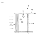
- Fig. 1 is a cross-sectional view of a sterilization and deodorization apparatus according to an embodiment.
- a sterilization and deodorization apparatus 10 may include a plasma unit or device 100 that forms a plasma region to generate OH radicals and ozone, a filter unit or filter 500 disposed to be spaced apart from the plasma unit 100 and having a plurality of through-holes, and a frame 600 that surrounds upper and lower ends of the plasma unit 100 and the filter unit 500 to support the plasma unit 100 and the filter unit 500.
- the frame 600 may include a first frame 601 disposed on the upper ends of the plasma unit 100 and the filter unit 500, and a second frame 602 disposed on the lower ends of the plasma unit 100 and the filter unit 500.
- the plasma unit 100 and the filter unit 500 may be supported within the frame 600 by the first and second frames 601 and 602.
- a light source 610 that irradiates light may be disposed on a bottom surface of the first frame 601.
- the light source 610 may be disposed on the bottom surface of the first frame 601 between the plasma unit 100 and the filter unit 500.
- a photocatalyst provided in the filter unit 500 may be activated by the light emitted from the light source 610.
- the light emitted from the light source 610 may have a wavelength of or in a visible light region.
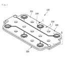
- FIG. 2 is a perspective view of a plasma unit or device according to an embodiment.
- FIG. 3 is an enlarged view illustrating a portion A of FIG. 2 .
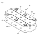
- Fig. 4 is an exploded perspective view of the plasma unit of Fig. 2 .
- the plasma unit or device 100 may include first and second substrates 200 and 300, which may be disposed opposite to each other.
- the second substrate 300 may be disposed below the first substrate 200, and the first and second substrates 200 and 300 may have a same size and shape.
- the first substrate 200 may be called an "upper plate”
- the second substrate 300 may be called a "lower plate”.
- a distance formation part or portion 400 by which the first and second substrates 200 and 300 are spaced by a set or predetermined distance d from each other may be provided between the first and second substrates 200 and 300.
- the set distance d may have a value of several micrometers ( ⁇ m).
- the first substrate 200 may include a first substrate body 201 having an approximately rectangular shape, and at least one first flow hole 250 that passes through the first substrate body 201 to guide a flow of air.
- a plurality of the first flow hole 250 may be provided. That is, as illustrated in Fig. 4 , 15 first flow holes 250 may be provided; however, embodiments are not limited to a number of flow holes.
- the first substrate 200 may include a first discharge electrode 240 including a pattern frame (see reference numeral 243 of Fig. 5 ) disposed to surround at least one first flow hole 250 of the plurality of first flow holes 250.
- the pattern frame 243 may surround 6 first flow holes 250 of the 15 first flow holes 250; however, embodiments are not limited thereto.
- the second substrate 300 may include a second substrate body 301 having an approximately rectangular shape, and at least one second flow hole 350 that passes through the second substrate body 301 to guide a flow of air.
- a plurality of the second flow hole 350 may be provided. That is, as illustrated in Fig. 5 , 15 second flow holes 350 may be provided, like the first flow holes 250; however, embodiments are not limited to a number of flow holes.
- the plurality of second flow holes 350 may communicate with the plurality of first flow holes 250, respectively.
- the plurality of second flow holes 350 may be defined below the plurality of first flow holes 250. While the plasma unit 100 operates to perform plasma discharge, air passing through the plurality of first and second flow holes 250 and 350 may be oxidized or decomposed.
- Fig. 5 is a plan view of a first substrate according to an embodiment.
- Fig. 6 is a plan view of a second substrate according to an embodiment.
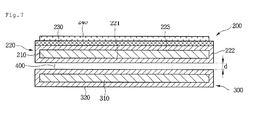
- Fig. 7 is a cross-sectional view taken along line VII-VII' of Fig. 2 .
- the first substrate 200 may include the first substrate body 201 having a plurality of the first flow holes 250, and the first discharge electrode 240 disposed on one surface of the first substrate body 201.
- the first substrate body 201 may include a ground electrode 210, a first insulator 220 that surrounds the ground electrode 210, and a photocatalyst part 230 disposed on at least one surface of the first insulator 220.
- the first substrate body 201 will be described in detail hereinbelow.
- the first discharge electrode 240 may include a discharge electrode part or portion 241 to which power may applied, the pattern frame 243, which may be disposed to surround at least a portion of the first flow holes 250, and at least one discharge tip 245 disposed on the pattern frame 245.
- a plurality of the pattern frame 243 may be provided.
- Each pattern frame 243 may include a closed pattern that surrounds the respective first flow hole 250. Further, each pattern frame 243 may have a circular shape, an oval shape, or a polygonal shape, for example.
- the at least one discharge tip 245 may protrude from an outer circumferential surface of the pattern frame 243.
- the first discharge electrode 240 may further include a connection line 242 that extends from the discharge electrode part 241 toward the plurality of pattern frames 243.
- the connection line 242 may be branched from the plurality of pattern frames 243.
- the first discharge electrode 240 may be formed by printing metal oxide paste, for example.
- a metal material of the metal oxide paste may be selected from the group consisting of tungsten, iron, copper, platinum, and silver, for example.
- the metal material may be silver (Ag).
- Silver oxide paste may be printed on the first discharge electrode 240.
- the silver oxide paste has a resistance of about 10 ⁇ to about 20 ⁇ , discharge may be easily performed due to low resistance. Thus, the discharge may be uniformly generated over the electrode. Also, the silver oxide paste may reduce an amount of ozone through the discharge.
- the second substrate 300 may include the second substrate body 301 having a plurality of the second flow holes 350.
- the second substrate body 301 may include a second discharge electrode 310, and a second insulator 320 that surrounds the second discharge electrode 310.
- the second substrate body 301 will be described hereinbelow with reference to Fig. 7 .
- the first substrate body 201 of the first substrate 200 may include the ground electrode 210 that interacts with the first discharge electrode 240 or the second discharge electrode 310 to perform the plasma discharge, and the first insulator 220 that surrounds the ground electrode 210 to prevent the ground electrode 210 from being exposed to the outside.
- the ground electrode 210 may be formed of a metal plate, for example, copper (Cu), and the first insulator 220 may be formed of an epoxy resin, for example.
- the first insulator 220 may include a bottom surface part or bottom surface 221, on which the ground electrode 221 may be seated, a side surface part or side surface 222 that extends upward from each of both sides of the bottom surface part 221, and a top surface part or top surface 223 coupled to an upper portion of the side surface part 222.
- An outside of the ground electrode 210 may be completely surrounded by the bottom surface part 221, the side surface part 222, and the top surface part 223 of the first insulator 210.
- the ground electrode 210 may be printed (masked) on an upper portion of the bottom surface part 221 of the first insulator 220.
- the bottom surface part 221 may be formed of an epoxy resin, for example, and may be understood as or refer to a "base" on which the ground electrode 210 may be disposed.
- a bottom surface of the ground electrode 210 may be covered by the first insulator 220, and side and top surfaces of the ground electrode 210 may be exposed to the outside.
- the side surface part 222 and the top surface part 223 of the first insulator 220 may be applied to the side and top surfaces of the ground electrode 210, which may be exposed to the outside.
- the applied side surface part 222 and top surface part 223 may be formed of the same epoxy resin as the bottom surface part 221.
- the photocatalyst part 230 which may react or be activated by visible light, may be disposed on the first insulator 220. That is, the photocatalyst part 230 may be disposed between the first insulator 220 and the first discharge electrode 240.
- the photocatalyst part 230 may decompose various harmful substances, perform antibacterial and sterilization functions, and reduce an amount of ozone, for example.
- the visible light may be understood as or refer to external light existing outside of the plasma unit 100.
- the visible light may include natural light or a lighting source that exists in a predetermined space.
- the photocatalyst part 230 may include a plurality of compositions.
- the plurality of composites may include silver phosphate (Ag 3 PO 4 ), titanium dioxide (TiO 2 ), and an inorganic binder, for example.
- the plurality of composites may include about 20 to about 50 parts by weight of silver phosphate (Ag 3 PO 4 ), about 5 to about 40 parts by weight of titanium dioxide (TiO 2 ), and about 10 to about 40 parts by weight of the inorganic binder.
- Titanium dioxide may have high activity when UV rays are irradiated and be chemically stable without being eroded by an acid, a base, and an organic solvent.
- Silver phosphate Silver phosphate
- Al 3 PO 4 may cause a catalytic activity reaction by optical energy having a visible-ray wavelength range of about 385 nm or more and a mean wavelength of about 500 nm.
- the photocatalyst part 230 may be effectively activated by the visible light.
- the silver phosphate (Ag 3 PO 4 ) in itself may have antibacterial (bacteria and mold, for example) performance, and a synergy effect, such as decomposition efficiency of organic materials (microorganisms and bad small components, for example) through simultaneous activity with titanium dioxide in low energy (the visible-ray wavelength range) by the silver phosphate (Ag 3 PO 4 ).
- the inorganic binder may include a polysilicate compound.
- the polysilicate compound may be composed of colloidal silica (SiO 2 ) and metal alkoxide, for example.
- the inorganic binder may include other additional components.
- the other components may be selected by a person skilled in the art in consideration of a final composition for coating.
- the inorganic binder may include a stabilizer, an acid catalyst, a hardener, and a metal additive, for example.
- the stabilizer may be selected from the group consisting of acetyl acetone, ethyl acetoacetate, iron acetoacetate, alkanolamine, and a combination thereof.
- the inorganic binder may contain about 0.1 parts to about 0.5 parts by weight of stabilizer.
- the acid catalyst may be selected from the group consisting of a phosphate metal catalyst, a nitrate metal catalyst, a phosphate-chloride composite metal catalyst, and a combination thereof.
- the inorganic binder may contain about 0.01 parts to about 0.5 parts by weight of acid catalyst.
- the hardener may be selected from the group consisting of aliphatic polyamine, crylonitrile-modified amine, polyaminde, amido amine, dicyandiamide, amide resin, isocyanate, melamine, and a combination thereof.
- the inorganic binder may contain about 0.05 parts to about 1 part by weight of hardener.
- An aluminum compound may be used as the metal additive.
- the aluminum compound may be prepared by mixing aluminum isopropoxide with aluminum chloride.
- the inorganic binder may contain about 0.05 parts to about 0.5 parts by weight of metal additive, for example.
- the photocatalyst part 230 may be provided in the form of a solution in which the plurality of composites are mixed with a predetermined solvent.
- the photocatalyst part 230 may be bonded to the top surface part 223 of the first insulator 220.
- the photocatalyst part 230 may be coupled to the top surface part 223 through coating.
- the coating may include dip coating, spray coating, or screen printing, for example.
- a drying temperature may vary according to characteristics of a base material for coating.
- the dip coating may be performed at a temperature of about 148°C to about 152°C for about 9 minutes to about 11 minutes.
- the photocatalyst part 230 may be prepared in the form of the solution and applied to a surface of the first substrate 200.
- the photocatalyst part 230 may be easily bonded to the surface of the first substrate 200 (bonding force securement).
- the photocatalyst 230 containing the above-described composites may be disposed on the top surface part 223, water (H 2 O) or oxygen (O 2 ) may change into reactive oxygen species (ROS) due to the catalyst effect of the photocatalyst 230.
- the reactive oxygen species may include hydroxy radical (OH - ), and hydrogen peroxide (H 2 O 2 ), for example.
- the reactive oxygen species (ROS) may perform strong sterilization (oxidation) and deodorization functions.
- reactive oxygen species (ROS) may decompose gas pollutants, such as toluene, and ammonia, for example, as well as biological pollutants, such as bacteria, and molds, for example, which consist of organic materials.
- the photocatalyst part 230 may prevent pollutants generated by air or moisture from being generated, that is, prevent dust from being accumulated or microorganisms from being propagated.
- the first substrate 200 may further include the first discharge electrode 240 disposed on the photocatalyst part 230.
- the first discharge electrode 240 may be formed by printing the metal oxide paste, for example.
- the first discharge electrode 240 When a high voltage which is above a firing voltage is applied to the first discharge electrode 240 including the ground electrode 210 and the pattern frame 243, a discharge phenomenon due to high electric fields may occur around the ground electrode 210 and the first discharge electrode 240. Also, free electrons moving around the ground electrode 210 and the first discharge electrode 240 may be accelerated by the electric fields to collide with neutral molecules (oxygen, and nitrogen, for example) of the air, thereby ionizing the neutral molecules. Thus, a large amount of ions may be generated. The air may be air flowing through the first flow hole 250.
- the first discharge electrode 240 may be understood as or refer to an "ion generation electrode" that generates ions.
- the second substrate 300 may be disposed to be spaced outward from the first substrate 200.
- the second substrate body 301 of the second substrate 300 may include the second discharge electrode 310 that acts with the ground electrode 210 to perform plasma discharge, and the second insulator 320 that surrounds the second discharge electrode 310 to prevent the second discharge electrode 310 from being exposed to the outside.
- the second ground electrode 310 may be formed of a metal plate, for example, copper (Cu), and the second insulator 320 may be formed of an epoxy resin.
- the second insulator 320 may include a bottom surface part or bottom surface, on which the second ground electrode 310 may be seated, a side surface part or side surface that extends upward from each of both sides of the bottom surface part, and a top surface part or top surface coupled to an upper portion of the side surface part.
- the second insulator 320 is similar to the first insulator 220, its detailed description has been omitted.
- An outside of the second discharge electrode 310 may be completely surrounded by the bottom surface part, the side surface part, and the top surface part of the second insulator 320.
- a method of manufacturing the second discharge electrode 310 and the second insulator 320 may be the same as the method of manufacturing the ground electrode 210 and the first insulator 220, and thus, repetitive description has been omitted.
- a high voltage which is above the firing voltage is applied to the ground electrode 210 and the second discharge electrode 310, dielectric breakdown between the ground electrode 210 and the second discharge electrode 310 may occur to cause the discharge phenomenon due to the high electric fields, thereby generating a strong plasma region. Also, the free electrons moving through the plasma region may be accelerated by the electric fields to react with the air. As a result, a large amount of OH radicals and ozone may be generated.
- the air may be air flowing through the second flow hole 350.
- the second discharge electrode 310 may be understood as or refer to a "surface discharge induced electrode" that generates radical ions.
- a region A in which the plasma unit 100 is disposed may be defined as a region in which a large amount of OH radicals, ions, and ozone are generated.
- Fig. 8 is a cross-sectional view of a filter unit or device according to an embodiment.
- the filter unit or filter 500 may include a filter frame 510 that defines a body of the filter unit 500, a body part or body 501 that surrounds the filter frame 510 to define an edge of the filter unit 500, and a photocatalyst 520 applied to the filter frame 500 to react with ozone generated from the plasma unit 100.
- the filter frame 510 may have a rectangular shape and may be fixed to the frame 600 by the body part 501.
- the filter frame 500 may have a plurality of through-holes, through which air passing through the plasma unit 100 may pass.
- the photocatalyst 520 may be applied to a mesh surface of the filter frame 510.
- the photocatalyst 520 may receive light to promote chemical reaction.
- the photocatalyst 520 may be titanium oxide (TiO 2 ).
- TiO 2 titanium oxide
- the photocatalyst 520 may perform a photocatalytic reaction through the light emitted from the light source 610.
- ions generated by the photocatalyst may flow to the outside through the through-hole.
- a region B in which the filter unit 600 is disposed may be defined as a photocatalytic reaction region.
- Fig. 9 is a cross-sectional view illustrating an operation of the sterilization and deodorization apparatus of Fig. 1 .
- the sterilization and deodorization apparatus 10 may be disposed so that air flows from the region A to the region B in a passage.
- a large amount of OH radicals and ozone may be generated in the region A by the plasma unit 100.
- the ozone (O 3 ), generated in the region A may contact a surface of the photocatalyst 520 to perform a first reaction.
- the first reaction may be expressed as follows.
- OH radicals and oxygen may be generated by the surface reaction between the ozone and the photocatalyst.
- the first reaction may be defined or referred to as a surface contact reaction.
- light emitted from the light source 610 may be irradiated onto the photocatalyst 520 to perform a second reaction on the photocatalyst 520 together with the ozone (O 3 ) generated in the region A.
- the second reaction may be expressed as follows.
- electrons (e - ) and holes (H + ) which have electric charges may be generated on the surface of the photocatalyst 520 by the light. Then, the electrons (e - ) and holes (H + ) may react with the ozone (O 3 ), generated in the region A and moisture (H 2 O) existing in the air to generate OH radicals and oxygen.
- the second reaction may be defined or referred to as an ozone-photocatalyst reaction.
- the reaction of the photocatalyst 520 may improve distribution efficiency using the ozone generated by the plasma unit 100 and the activation reaction of the filter unit 500 when compared to a single reaction of the photocatalyst 520. Also, as ozone generated by the plasma unit 100 is decomposed to generate the OH radicals, air having no ozone may be supplied ultimately.
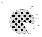
- Fig. 10 is a cross-sectional view of a filter unit or filter according to another embodiment.
- Fig. 11 is a side cross-sectional view of the filter unit of Fig. 10 .
- This embodiment may be similar to the previous embodiment except for a filter unit or filter. Thus, only characterized parts of this embodiment will be principally described below, and descriptions of the same parts as that of the previous embodiment will not be repeated.
- a filter unit or filter 700 may include a filter frame 710 having a plurality of through-holes, photocatalyst 520 applied to the filter frame 710, and a light source part or light source 730 that irradiates light onto at least a portion of the filter frame 710 and coupled to the filter frame 710.
- the filter frame 710 may have a circular shape.
- the plurality of through-holes may be defined in the filter frame 710 having a circular shape so that air may flow therethrough.
- the photocatalyst 520 may be applied to one surface or both surfaces of the filter frame 710.
- a body part or body that surrounds the filter frame 710 may be disposed on or at an edge of the filter frame 710 along the edge of the filter frame 710, like the previous embodiment.
- upper and lower ends of the filter frame 710 may be fixed to frame 600.
- the light source part 730 may surround at least a portion of both surfaces of the filter frame 730 and be coupled to the filter frame 730 so that the light source part 730 may be rotatable in a clockwise direction or a counterclockwise direction.
- the light source part 730 may be rotated by coupling a drive motor 740 and a shaft 750 connected to the drive motor 740 to one side of the light source part 730.
- a rotation rate of the light source part 730 may be controlled by a control unit or controller (not shown).
- the light source part 730 may have a fan shape having a predetermined angle.
- the light source part 730 may include a first horizontal part or portion 731 that covers at least a portion of one or a first surface of the filter frame 730, a second horizontal part or portion 732 that covers at least a portion of the other or a second surface of the filter frame 730, and a vertical part 733 that connects the first horizontal part 731 to the second horizontal part 732.
- the first horizontal part 731 and the second horizontal part 732 may have a same shape. That is, each of the first and second horizontal parts 731 and 732 may have a fan shape that covers at least a portion of the filter frame 710 having the circular shape and has a predetermined angle. Also, a portion of the filter frame 710 may be inserted into a groove 735 defined by the first horizontal part 731, the second horizontal part 732, and the vertical part 733.
- a light source may be disposed on a surface that faces the filter frame 710 on the first and second horizontal parts 731 and 732. That is, light may be irradiated onto the filter frame 710 inside of the groove 735. Also, the light is not radiated onto a portion of the filter frame 710 that is not accommodated into the groove 735.
- the light source part 730 may rotate to irradiate light onto only a portion of the filter frame 710, thereby causing a photocatalytic reaction.
- the light source part 710 may be rotated to irradiate light onto other portions of the filter frame 710, thereby continuously causing the photocatalytic reaction.
- the light source part 730 may be fixed, and the filter frame 710 may be rotated to uniformly irradiate light onto the filter frame 710.
- a rotational shaft may be connected to a center of the filter frame 710, and the filter frame 710 may be controlled at an adequate rotation rate to rotate in a clockwise direction or a counterclockwise direction.
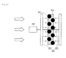
- Fig. 12 is a cross-sectional view of a filter unit or filter according to still another embodiment.
- Fig. 13 is a side cross-sectional view of the filter unit of Fig. 12 .
- This embodiment may be similar to the previous embodiments except for a filter unit or filter. Thus, only characterized parts of this embodiment will be principally described below, and descriptions of the same parts as that of the previous embodiments will not be repeated.
- a filter unit or filter 800 may include a filter frame 810 having a plurality of through-holes, photocatalyst 520 applied to the filter frame 810, and a light source part or light source 830 that irradiates light onto at least a portion of the filter frame 810 and rotatably coupled to the filter frame 810.
- the filter frame 810 may have a circular shape.
- a plurality of through-holes may be defined in the filter frame 810 having a circular shape so that air may flow therethrough.
- the photocatalyst 520 may be applied to one surface or both surfaces of the filter frame 810.
- a body part or body that surrounds the filter frame 810 may be disposed on or at an edge of the filter frame 810 along the edge of the filter frame 810, like the previous embodiment.
- upper and lower ends of the filter frame 810 may be fixed to frame 600.
- the light source part 830 may include a light irradiation part or portion 831 disposed on each of both surfaces of the filter frame 810, and a rotational shaft 832 that passes through a center of the filter frame 810 to allow the light irradiation part 831 to rotate.
- the light irradiation part 831 may have a relatively large bar shape having a length greater than a diameter of the filter frame 810.
- a light source may be disposed on a surface of the light irradiation part 831 that faces the filter frame 810.
- the rotational shaft 832 may have one side connected to a drive motor 840 to transmit a drive force of the drive motor 840 to the light irradiation part 831.
- the photocatalyst 520 applied to the filter frame 810 may react with the light. As the light is not irradiated onto a portion of the filter frame 810 that does not face the light irradiation part 831, the reaction may not occur.
- the light source part 830 may rotate to irradiate light onto only a portion of the filter frame 810, thereby causing a photocatalytic reaction.
- the light source part 830 may rotate to continuously irradiate light onto other portions of the filter frame 810, thereby continuously causing the photocatalyst reaction.
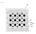
- Fig. 14 is a cross-sectional view of a filter unit or filter according to still another embodiment.
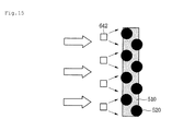
- Fig. 15 is a side cross-sectional view of the filter unit of Fig. 14 .
- This embodiment may be similar to the previous embodiments except for a filter unit or filter. Thus, only characterized parts of this embodiment will be principally described below, and descriptions of the same parts as that of the previous embodiments will not be repeated.
- a filter unit or filter 900 may include filter frame 510 having a plurality of through-holes, photocatalyst 520 applied to the filter frame 510, and a light source part or light source 640 disposed to be spaced apart from the filter frame 510 to irradiate light to the filter frame 510.
- the light source part 640 may include a light source frame 641 that defines an outer frame, and a plurality of light sources 642 disposed on the light source frame 641 in a line. Referring to Fig. 14 , four light sources 642 may be horizontally disposed on the light source frame 641, as shown in Fig. 14 ; however, embodiments are not limited thereto.
- Each of the plurality of light sources 642 may irradiate light to the filter frame 510.
- the photocatalyst 520 applied to the filter frame 510 may react with the light.
- the plurality of light sources 642 may be disposed at a predetermined distance on the light source frame 641, the light may be uniformly irradiated onto an entire surface of the filter frame 510 to quickly perform the photocatalytic reaction.
- the sterilization and deodorization apparatus may have at least the following advantages.
- ozone generated from the plasma unit is converted into the OH radicals through or by the photocatalyst, an amount of ozone may be reduced. Thus, bad smells and pollutants may be efficiently removed.
- the filter may be easily recycled, and also the product may be easily designed.
- Embodiments disclosed herein provide a sterilization and deodorization apparatus that is capable of removing pollutants.
- Embodiments disclosed herein provide a sterilization and deodorization apparatus that may include a frame that defines an outer appearance; a plasma unit or device disposed on or at one or a first side of the frame, the plasma unit forming a plasma region to generate a plurality of ions; and a filter unit or filter disposed on or at the other or a second side of the frame which is spaced apart from the frame unit.
- the filter unit may include a filter frame having a plurality of through-holes so that air may pass therethrough; and a photocatalyst applied to the filter frame to perform photocatalytic reaction.
- the sterilization and deodorization apparatus may further include a light source disposed on or at one side of the frame to irradiate light onto the filter unit. The light irradiated from the light source may have a wavelength of visible light region.
- the air may flow from the plasma unit to the filter unit.
- the plurality of ions may include ozone (O 3 ), and the photocatalyst may include titanium oxide (TiO 2 ).
- the sterilization and deodorization apparatus may further include a light source part or light source rotatably coupled to the filter frame, that irradiates light onto at least a portion of the filter frame.
- the light source part may include a first horizontal part or portion that covers a portion of one or a first surface of the filter frame; a second horizontal part or portion having a same shape as the first horizontal part, the second horizontal part covering a portion of the other or a second surface of the filter frame; and a vertical part that connects the first horizontal part to the second horizontal part, and a light source that irradiates light onto the filter frame disposed on each of the first and second horizontal parts.
- the sterilization and deodorization apparatus may further include a drive motor disposed on or at one side of the light source part to rotate the light source part.
- the sterilization and deodorization apparatus may further include a light source part or portion that covers at least a portion of the filter frame.
- the at least a portion of the filter frame may be covered by the light source part to rotate.
- the light source part may include a first horizontal part or portion that covers a portion of one or a first surface of the filter frame; a second horizontal part or portion having a same shape as the first horizontal part, the second horizontal part covering a portion of the other or a second surface of the filter frame; a vertical part that connects the first horizontal part to the second horizontal part; and a light source that irradiates light onto the filter frame disposed on each of the first and second horizontal parts.
- the sterilization and deodorization apparatus may further include a light source part or light source disposed to be spaced apart from the filter frame to irradiate light onto the filter frame.
- the light source part may include a light source frame that defines an outer frame; and a plurality of light sources disposed on the light source frame in a line to irradiate light onto the filter frame.
- the plasma unit may include first and second substrates, which may be disposed opposite to each other, and a distance formation part that spaces the first and second substrates from each other disposed between the first and second substrates.
- the first substrate may include a first substrate body having a plate shape; at least one first flow hole that passes through the first substrate body to guide a flow of air; and a pattern frame disposed to surround at least a portion of the first flow hole.
- the second substrate may include a second substrate body having a plate shape; and at least one second flow hole that passes through the second substrate body to guide a flow of air.
- the pattern frame may include a closed pattern that surrounds the first flow hole; and a discharge tip that protrudes from an outer circumferential surface of the pattern.
- the photocatalyst may be applied to a mesh surface of the filter frame, which may be formed by the plurality of through-holes.
- Embodiments disclosed herein further provide a sterilization and deodorization apparatus that may include a frame in which air flows; a plasma unit or device disposed inside of the frame, the plasma unit forming a plasma region to generate a plurality of ions; a filter unit or filter disposed to be spaced apart from the plasma unit inside of the frame, the filter unit including a filter frame to which a photocatalyst that performs a photocatalytic reaction may be applied; and a light source disposed between the plasma unit and the filter unit inside of the frame to irradiate light onto the filter unit.
- the light irradiated from the light source may have a wavelength of a visible light region.
- the air may flow from the plasma unit to the filter unit.
- the plurality of ions may include ozone (O 3 ), and the photocatalyst may include titanium oxide (TiO 2 ).
- the filter frame may have a plurality of through-holes so that the air may pass therethrough.
- the photocatalyst may be applied to a mesh surface of the filter frame, which may be formed by the plurality of through-holes.
- any reference in this specification to "one embodiment,” “an embodiment,” “example embodiment,” etc. means that a particular feature, structure, or characteristic described in connection with the embodiment is included in at least one embodiment.
- the appearances of such phrases in various places in the specification are not necessarily all referring to the same embodiment.
Landscapes
- Health & Medical Sciences (AREA)
- Engineering & Computer Science (AREA)
- Plasma & Fusion (AREA)
- Physics & Mathematics (AREA)
- General Health & Medical Sciences (AREA)
- Life Sciences & Earth Sciences (AREA)
- Animal Behavior & Ethology (AREA)
- Epidemiology (AREA)
- Public Health (AREA)
- Veterinary Medicine (AREA)
- Chemical & Material Sciences (AREA)
- Spectroscopy & Molecular Physics (AREA)
- Combustion & Propulsion (AREA)
- Mechanical Engineering (AREA)
- General Engineering & Computer Science (AREA)
- Chemical Kinetics & Catalysis (AREA)
- Disinfection, Sterilisation Or Deodorisation Of Air (AREA)
- Physical Or Chemical Processes And Apparatus (AREA)
Priority Applications (1)
| Application Number | Priority Date | Filing Date | Title |
|---|---|---|---|
| EP21200563.1A EP3984567B1 (de) | 2014-07-16 | 2015-07-15 | Sterilisations- und desodorierungsvorrichtung |
Applications Claiming Priority (1)
| Application Number | Priority Date | Filing Date | Title |
|---|---|---|---|
| KR1020140089497A KR102259353B1 (ko) | 2014-07-16 | 2014-07-16 | 살균 탈취 장치 |
Related Child Applications (2)
| Application Number | Title | Priority Date | Filing Date |
|---|---|---|---|
| EP21200563.1A Division EP3984567B1 (de) | 2014-07-16 | 2015-07-15 | Sterilisations- und desodorierungsvorrichtung |
| EP21200563.1A Division-Into EP3984567B1 (de) | 2014-07-16 | 2015-07-15 | Sterilisations- und desodorierungsvorrichtung |
Publications (3)
| Publication Number | Publication Date |
|---|---|
| EP2974750A2 true EP2974750A2 (de) | 2016-01-20 |
| EP2974750A3 EP2974750A3 (de) | 2016-08-10 |
| EP2974750B1 EP2974750B1 (de) | 2023-01-11 |
Family
ID=54007467
Family Applications (2)
| Application Number | Title | Priority Date | Filing Date |
|---|---|---|---|
| EP15176824.9A Active EP2974750B1 (de) | 2014-07-16 | 2015-07-15 | Sterilisations- und desodorierungsvorrichtung |
| EP21200563.1A Active EP3984567B1 (de) | 2014-07-16 | 2015-07-15 | Sterilisations- und desodorierungsvorrichtung |
Family Applications After (1)
| Application Number | Title | Priority Date | Filing Date |
|---|---|---|---|
| EP21200563.1A Active EP3984567B1 (de) | 2014-07-16 | 2015-07-15 | Sterilisations- und desodorierungsvorrichtung |
Country Status (4)
| Country | Link |
|---|---|
| US (1) | US9474822B2 (de) |
| EP (2) | EP2974750B1 (de) |
| KR (3) | KR102259353B1 (de) |
| CN (1) | CN105268011B (de) |
Families Citing this family (15)
| Publication number | Priority date | Publication date | Assignee | Title |
|---|---|---|---|---|
| KR102076660B1 (ko) * | 2012-06-21 | 2020-02-12 | 엘지전자 주식회사 | 공기 조화기 및 그 제어방법 |
| KR20170068232A (ko) * | 2015-12-09 | 2017-06-19 | 엘지전자 주식회사 | 플라즈마 전극장치, 그 제조방법 및 공기조화기 |
| US10117960B2 (en) * | 2016-09-19 | 2018-11-06 | Wallace Noonan | Air treating apparatus for pet sanitary station and methods of mounting and dosing said apparatus |
| KR20190090959A (ko) * | 2018-01-26 | 2019-08-05 | 서울바이오시스 주식회사 | 유체 처리 장치 |
| JP7438657B2 (ja) * | 2018-08-31 | 2024-02-27 | トヨタ紡織株式会社 | 空気浄化装置、及び空気浄化方法 |
| CN109046015A (zh) * | 2018-09-13 | 2018-12-21 | 龚娟 | 一种甲醛清除剂的制备方法 |
| CN109012166A (zh) * | 2018-09-13 | 2018-12-18 | 龚娟 | 一种复合甲醛清除剂的制备方法 |
| KR102952389B1 (ko) * | 2020-07-13 | 2026-04-14 | 현대자동차주식회사 | 광촉매 모듈을 구비한 차량용 공조장치 |
| US11612673B2 (en) | 2020-08-31 | 2023-03-28 | Promethium Limited | Photoactivated semiconductor photocatalytic air purification |
| US11623018B2 (en) | 2020-08-31 | 2023-04-11 | Promethium Limited | Photoactivated semiconductor photocatalytic air purification |
| CN114165970A (zh) * | 2020-09-10 | 2022-03-11 | emz-汉拿两合有限公司 | 用于家用电器的空气处理设备 |
| US11471551B1 (en) | 2021-09-09 | 2022-10-18 | Micron Pure, Llc | Apparatus for inactivation of airborne pathogens |
| KR102458760B1 (ko) * | 2022-06-15 | 2022-10-26 | 주식회사 화인아이앤씨 | 항바이러스 기능을 가지는 스탠드형 전열교환기 |
| KR102459078B1 (ko) * | 2022-06-15 | 2022-10-26 | 주식회사 화인아이앤씨 | 항바이러스 기능을 갖는 전열교환기 |
| KR102807043B1 (ko) * | 2024-08-21 | 2025-05-14 | 박문수 | 필터소자용 살균장치 |
Citations (1)
| Publication number | Priority date | Publication date | Assignee | Title |
|---|---|---|---|---|
| KR100657476B1 (ko) | 2004-09-14 | 2006-12-13 | 엘지전자 주식회사 | 연면 방전형 공기정화장치 |
Family Cites Families (30)
| Publication number | Priority date | Publication date | Assignee | Title |
|---|---|---|---|---|
| JP2000051332A (ja) * | 1998-08-03 | 2000-02-22 | Daikin Ind Ltd | 空気清浄機 |
| JP2000246116A (ja) | 1999-02-26 | 2000-09-12 | Kyowa Gijutsu Keikaku Kk | 回転式光触媒付与構造体気液体浄化筒 |
| JP2004263985A (ja) * | 2003-03-04 | 2004-09-24 | Matsushita Electric Ind Co Ltd | 空気清浄化方法とその装置 |
| WO2004108294A1 (ja) | 2003-06-05 | 2004-12-16 | Daikin Industries, Ltd. | 放電装置及び空気浄化装置 |
| KR20050019692A (ko) * | 2003-08-21 | 2005-03-03 | 주식회사제4기한국 | 공조라인에 설치가능한 공기살균 청정유닛 |
| JP2005144445A (ja) * | 2003-10-24 | 2005-06-09 | Yamaha Corp | 非平衡プラズマによるガス処理方法と放電電極及びそれを備えたガス処理装置 |
| KR200340227Y1 (ko) | 2003-10-29 | 2004-01-31 | 김병훈 | 광촉매를 이용한 공기살균기 |
| KR100543330B1 (ko) * | 2003-12-26 | 2006-01-20 | 삼성전자주식회사 | 탈취필터를 갖춘 공기청정기 |
| JP4608630B2 (ja) | 2005-02-21 | 2011-01-12 | 独立行政法人産業技術総合研究所 | イオン発生器及び除電器 |
| FR2892950B1 (fr) | 2005-11-07 | 2008-02-15 | Ahlstrom Res And Services Sa | Traitement combine d'effluents gazeux par plasma froid et photocatatyse |
| EP1968740B8 (de) | 2005-12-17 | 2017-02-22 | AirInSpace S.E. | Luftreinigungsvorrichtungen |
| JP4561710B2 (ja) | 2006-01-19 | 2010-10-13 | ダイキン工業株式会社 | 脱臭機能再生装置 |
| US8003058B2 (en) * | 2006-08-09 | 2011-08-23 | Airinspace B.V. | Air purification devices |
| KR20080056479A (ko) * | 2006-12-18 | 2008-06-23 | 삼성전자주식회사 | 이온발생장치 |
| US20090010801A1 (en) * | 2007-05-15 | 2009-01-08 | Murphy Oliver J | Air cleaner |
| US7674436B1 (en) | 2008-05-27 | 2010-03-09 | Vladimir Feldman | Portable indoor air purification system |
| JP5078792B2 (ja) * | 2008-07-29 | 2012-11-21 | 京セラ株式会社 | 誘電性構造体、誘電性構造体を用いた放電装置、流体改質装置、および反応システム |
| KR20100029668A (ko) * | 2008-09-08 | 2010-03-17 | 권대웅 | 자외선램프를 이용한 광촉매 공기청정펜 |
| CN201363832Y (zh) * | 2008-11-19 | 2009-12-16 | 幸乾富 | 具有空气消毒灭菌功能的风机盘管空调器 |
| US8498092B2 (en) * | 2008-12-23 | 2013-07-30 | Oxion, PTE, Ltd | Air ionizer electrode assembly |
| JP5349038B2 (ja) * | 2008-12-25 | 2013-11-20 | 京セラ株式会社 | 誘電性構造体、誘電性構造体を用いた放電装置、流体改質装置、および反応システム |
| DE102010044252B4 (de) | 2010-09-02 | 2014-03-27 | Reinhausen Plasma Gmbh | Vorrichtung und Verfahren zur Erzeugung einer Barriereentladung in einem Gasstrom |
| JP5584776B2 (ja) | 2010-10-27 | 2014-09-03 | 京セラ株式会社 | イオン風発生体及びイオン風発生装置 |
| EP2638959A4 (de) | 2010-11-09 | 2015-02-11 | Samsung Electronics Co Ltd | Plasmagenerator und plasmaerzeugungsverfahren |
| EP2790472A4 (de) * | 2011-12-08 | 2015-07-29 | Samsung Electronics Co Ltd | Plasmagenerator |
| KR101904939B1 (ko) * | 2011-12-15 | 2018-10-08 | 엘지전자 주식회사 | 이온발생용 전극 구조체, 이의 제조 방법 및 이를 이용한 이온발생장치 |
| JP6243626B2 (ja) | 2012-05-14 | 2017-12-06 | マイクロプラズマ株式会社 | 低電圧プラズマ発生用電極 |
| KR102076660B1 (ko) * | 2012-06-21 | 2020-02-12 | 엘지전자 주식회사 | 공기 조화기 및 그 제어방법 |
| KR101419481B1 (ko) * | 2012-11-16 | 2014-07-14 | 주식회사 퓨어시스 | 탈취 촉매 필터 및 이의 재생 유닛을 구비한 공기제연정화 살균기 |
| KR102186432B1 (ko) | 2014-03-25 | 2020-12-03 | 엘지전자 주식회사 | 플라즈마 전극장치 |
-
2014
- 2014-07-16 KR KR1020140089497A patent/KR102259353B1/ko active Active
-
2015
- 2015-05-08 CN CN201510230607.3A patent/CN105268011B/zh active Active
- 2015-07-15 EP EP15176824.9A patent/EP2974750B1/de active Active
- 2015-07-15 US US14/799,941 patent/US9474822B2/en active Active
- 2015-07-15 EP EP21200563.1A patent/EP3984567B1/de active Active
-
2021
- 2021-05-24 KR KR1020210066309A patent/KR102376629B1/ko active Active
-
2022
- 2022-03-14 KR KR1020220031269A patent/KR102431589B1/ko active Active
Patent Citations (1)
| Publication number | Priority date | Publication date | Assignee | Title |
|---|---|---|---|---|
| KR100657476B1 (ko) | 2004-09-14 | 2006-12-13 | 엘지전자 주식회사 | 연면 방전형 공기정화장치 |
Also Published As
| Publication number | Publication date |
|---|---|
| US9474822B2 (en) | 2016-10-25 |
| KR102431589B1 (ko) | 2022-08-11 |
| KR20220039676A (ko) | 2022-03-29 |
| EP2974750A3 (de) | 2016-08-10 |
| KR20210065906A (ko) | 2021-06-04 |
| KR20160009260A (ko) | 2016-01-26 |
| CN105268011B (zh) | 2018-04-13 |
| CN105268011A (zh) | 2016-01-27 |
| KR102376629B1 (ko) | 2022-03-21 |
| EP3984567A2 (de) | 2022-04-20 |
| US20160015848A1 (en) | 2016-01-21 |
| KR102259353B1 (ko) | 2021-06-02 |
| EP2974750B1 (de) | 2023-01-11 |
| EP3984567A3 (de) | 2022-08-03 |
| EP3984567B1 (de) | 2024-01-17 |
Similar Documents
| Publication | Publication Date | Title |
|---|---|---|
| EP2974750B1 (de) | Sterilisations- und desodorierungsvorrichtung | |
| US9646806B2 (en) | Plasma electrode device and method for manufacturing the same | |
| EP2974783A1 (de) | Plasma-elektrodenvorrichtung und luftklimatisierungsvorrichtung | |
| AU745172B2 (en) | Electrostatic precipitator | |
| KR102439532B1 (ko) | 공기정화 및 살균 기능을 지닌 에어샤워 장치 | |
| MX2008000989A (es) | Sistema y metodo para reducir y acondicionar aire para reducir compuestos organicos volatiles y ozono. | |
| KR20170068232A (ko) | 플라즈마 전극장치, 그 제조방법 및 공기조화기 | |
| US20050046356A1 (en) | Lighting apparatus for generating anions and purifying air | |
| CN107062452A (zh) | 一种顶吸式层流型空气净化消毒机 | |
| TWM628958U (zh) | 滅菌消毒的等離子空氣清淨機 | |
| CN1609523A (zh) | 高吸附性多功能空气净化器 | |
| KR100754014B1 (ko) | 차량용 실내 공기정화 장치 | |
| KR100249197B1 (ko) | 전기집진기 | |
| WO2021204573A1 (en) | Fluid treatment unit | |
| CN216799377U (zh) | 灭菌消毒的等离子空气清净机 | |
| KR102749779B1 (ko) | 복합 공기 청정살균 장치 | |
| CN215388458U (zh) | 一种用于垃圾刺激性气体的净化装置 | |
| CN201304128Y (zh) | 一种正负离子空气洁净机 | |
| KR200312720Y1 (ko) | 광촉매를 구비한 공기정화용 조화 | |
| KR20180118567A (ko) | 플라즈마 발생장치 | |
| JP3108187U (ja) | 空気清浄化装置 | |
| CN117781394A (zh) | 一种净化模块、空气处理器和空调 | |
| KR101544728B1 (ko) | 통풍 관로가 구비된 플라즈마 이온 발생 장치 | |
| KR19990068989A (ko) | 탈취촉매체와 그 제조방법 및 그를 이용한 공기정화장치 |
Legal Events
| Date | Code | Title | Description |
|---|---|---|---|
| PUAI | Public reference made under article 153(3) epc to a published international application that has entered the european phase |
Free format text: ORIGINAL CODE: 0009012 |
|
| 17P | Request for examination filed |
Effective date: 20150815 |
|
| AK | Designated contracting states |
Kind code of ref document: A2 Designated state(s): AL AT BE BG CH CY CZ DE DK EE ES FI FR GB GR HR HU IE IS IT LI LT LU LV MC MK MT NL NO PL PT RO RS SE SI SK SM TR |
|
| AX | Request for extension of the european patent |
Extension state: BA ME |
|
| PUAL | Search report despatched |
Free format text: ORIGINAL CODE: 0009013 |
|
| AK | Designated contracting states |
Kind code of ref document: A3 Designated state(s): AL AT BE BG CH CY CZ DE DK EE ES FI FR GB GR HR HU IE IS IT LI LT LU LV MC MK MT NL NO PL PT RO RS SE SI SK SM TR |
|
| AX | Request for extension of the european patent |
Extension state: BA ME |
|
| RIC1 | Information provided on ipc code assigned before grant |
Ipc: A61L 9/22 20060101AFI20160303BHEP |
|
| PUAF | Information related to the publication of a search report (a3 document) modified or deleted |
Free format text: ORIGINAL CODE: 0009199SEPU |
|
| D17D | Deferred search report published (deleted) | ||
| PUAL | Search report despatched |
Free format text: ORIGINAL CODE: 0009013 |
|
| AK | Designated contracting states |
Kind code of ref document: A3 Designated state(s): AL AT BE BG CH CY CZ DE DK EE ES FI FR GB GR HR HU IE IS IT LI LT LU LV MC MK MT NL NO PL PT RO RS SE SI SK SM TR |
|
| AX | Request for extension of the european patent |
Extension state: BA ME |
|
| RIC1 | Information provided on ipc code assigned before grant |
Ipc: A61L 9/22 20060101AFI20160707BHEP |
|
| RBV | Designated contracting states (corrected) |
Designated state(s): AL AT BE BG CH CY CZ DE DK EE ES FI FR GB GR HR HU IE IS IT LI LT LU LV MC MK MT NL NO PL PT RO RS SE SI SK SM TR |
|
| STAA | Information on the status of an ep patent application or granted ep patent |
Free format text: STATUS: EXAMINATION IS IN PROGRESS |
|
| 17Q | First examination report despatched |
Effective date: 20210519 |
|
| GRAP | Despatch of communication of intention to grant a patent |
Free format text: ORIGINAL CODE: EPIDOSNIGR1 |
|
| STAA | Information on the status of an ep patent application or granted ep patent |
Free format text: STATUS: GRANT OF PATENT IS INTENDED |
|
| INTG | Intention to grant announced |
Effective date: 20220804 |
|
| GRAS | Grant fee paid |
Free format text: ORIGINAL CODE: EPIDOSNIGR3 |
|
| GRAA | (expected) grant |
Free format text: ORIGINAL CODE: 0009210 |
|
| STAA | Information on the status of an ep patent application or granted ep patent |
Free format text: STATUS: THE PATENT HAS BEEN GRANTED |
|
| AK | Designated contracting states |
Kind code of ref document: B1 Designated state(s): AL AT BE BG CH CY CZ DE DK EE ES FI FR GB GR HR HU IE IS IT LI LT LU LV MC MK MT NL NO PL PT RO RS SE SI SK SM TR |
|
| REG | Reference to a national code |
Ref country code: GB Ref legal event code: FG4D |
|
| REG | Reference to a national code |
Ref country code: CH Ref legal event code: EP |
|
| REG | Reference to a national code |
Ref country code: DE Ref legal event code: R096 Ref document number: 602015082242 Country of ref document: DE |
|
| REG | Reference to a national code |
Ref country code: IE Ref legal event code: FG4D |
|
| REG | Reference to a national code |
Ref country code: AT Ref legal event code: REF Ref document number: 1543013 Country of ref document: AT Kind code of ref document: T Effective date: 20230215 |
|
| REG | Reference to a national code |
Ref country code: LT Ref legal event code: MG9D |
|
| REG | Reference to a national code |
Ref country code: NL Ref legal event code: MP Effective date: 20230111 |
|
| REG | Reference to a national code |
Ref country code: AT Ref legal event code: MK05 Ref document number: 1543013 Country of ref document: AT Kind code of ref document: T Effective date: 20230111 |
|
| PG25 | Lapsed in a contracting state [announced via postgrant information from national office to epo] |
Ref country code: NL Free format text: LAPSE BECAUSE OF FAILURE TO SUBMIT A TRANSLATION OF THE DESCRIPTION OR TO PAY THE FEE WITHIN THE PRESCRIBED TIME-LIMIT Effective date: 20230111 |
|
| PG25 | Lapsed in a contracting state [announced via postgrant information from national office to epo] |
Ref country code: RS Free format text: LAPSE BECAUSE OF FAILURE TO SUBMIT A TRANSLATION OF THE DESCRIPTION OR TO PAY THE FEE WITHIN THE PRESCRIBED TIME-LIMIT Effective date: 20230111 Ref country code: PT Free format text: LAPSE BECAUSE OF FAILURE TO SUBMIT A TRANSLATION OF THE DESCRIPTION OR TO PAY THE FEE WITHIN THE PRESCRIBED TIME-LIMIT Effective date: 20230511 Ref country code: NO Free format text: LAPSE BECAUSE OF FAILURE TO SUBMIT A TRANSLATION OF THE DESCRIPTION OR TO PAY THE FEE WITHIN THE PRESCRIBED TIME-LIMIT Effective date: 20230411 Ref country code: LV Free format text: LAPSE BECAUSE OF FAILURE TO SUBMIT A TRANSLATION OF THE DESCRIPTION OR TO PAY THE FEE WITHIN THE PRESCRIBED TIME-LIMIT Effective date: 20230111 Ref country code: LT Free format text: LAPSE BECAUSE OF FAILURE TO SUBMIT A TRANSLATION OF THE DESCRIPTION OR TO PAY THE FEE WITHIN THE PRESCRIBED TIME-LIMIT Effective date: 20230111 Ref country code: HR Free format text: LAPSE BECAUSE OF FAILURE TO SUBMIT A TRANSLATION OF THE DESCRIPTION OR TO PAY THE FEE WITHIN THE PRESCRIBED TIME-LIMIT Effective date: 20230111 Ref country code: ES Free format text: LAPSE BECAUSE OF FAILURE TO SUBMIT A TRANSLATION OF THE DESCRIPTION OR TO PAY THE FEE WITHIN THE PRESCRIBED TIME-LIMIT Effective date: 20230111 Ref country code: AT Free format text: LAPSE BECAUSE OF FAILURE TO SUBMIT A TRANSLATION OF THE DESCRIPTION OR TO PAY THE FEE WITHIN THE PRESCRIBED TIME-LIMIT Effective date: 20230111 |
|
| PG25 | Lapsed in a contracting state [announced via postgrant information from national office to epo] |
Ref country code: SE Free format text: LAPSE BECAUSE OF FAILURE TO SUBMIT A TRANSLATION OF THE DESCRIPTION OR TO PAY THE FEE WITHIN THE PRESCRIBED TIME-LIMIT Effective date: 20230111 Ref country code: PL Free format text: LAPSE BECAUSE OF FAILURE TO SUBMIT A TRANSLATION OF THE DESCRIPTION OR TO PAY THE FEE WITHIN THE PRESCRIBED TIME-LIMIT Effective date: 20230111 Ref country code: IS Free format text: LAPSE BECAUSE OF FAILURE TO SUBMIT A TRANSLATION OF THE DESCRIPTION OR TO PAY THE FEE WITHIN THE PRESCRIBED TIME-LIMIT Effective date: 20230511 Ref country code: GR Free format text: LAPSE BECAUSE OF FAILURE TO SUBMIT A TRANSLATION OF THE DESCRIPTION OR TO PAY THE FEE WITHIN THE PRESCRIBED TIME-LIMIT Effective date: 20230412 Ref country code: FI Free format text: LAPSE BECAUSE OF FAILURE TO SUBMIT A TRANSLATION OF THE DESCRIPTION OR TO PAY THE FEE WITHIN THE PRESCRIBED TIME-LIMIT Effective date: 20230111 |
|
| REG | Reference to a national code |
Ref country code: DE Ref legal event code: R097 Ref document number: 602015082242 Country of ref document: DE |
|
| PG25 | Lapsed in a contracting state [announced via postgrant information from national office to epo] |
Ref country code: SM Free format text: LAPSE BECAUSE OF FAILURE TO SUBMIT A TRANSLATION OF THE DESCRIPTION OR TO PAY THE FEE WITHIN THE PRESCRIBED TIME-LIMIT Effective date: 20230111 Ref country code: RO Free format text: LAPSE BECAUSE OF FAILURE TO SUBMIT A TRANSLATION OF THE DESCRIPTION OR TO PAY THE FEE WITHIN THE PRESCRIBED TIME-LIMIT Effective date: 20230111 Ref country code: EE Free format text: LAPSE BECAUSE OF FAILURE TO SUBMIT A TRANSLATION OF THE DESCRIPTION OR TO PAY THE FEE WITHIN THE PRESCRIBED TIME-LIMIT Effective date: 20230111 Ref country code: DK Free format text: LAPSE BECAUSE OF FAILURE TO SUBMIT A TRANSLATION OF THE DESCRIPTION OR TO PAY THE FEE WITHIN THE PRESCRIBED TIME-LIMIT Effective date: 20230111 Ref country code: CZ Free format text: LAPSE BECAUSE OF FAILURE TO SUBMIT A TRANSLATION OF THE DESCRIPTION OR TO PAY THE FEE WITHIN THE PRESCRIBED TIME-LIMIT Effective date: 20230111 |
|
| PLBE | No opposition filed within time limit |
Free format text: ORIGINAL CODE: 0009261 |
|
| STAA | Information on the status of an ep patent application or granted ep patent |
Free format text: STATUS: NO OPPOSITION FILED WITHIN TIME LIMIT |
|
| PG25 | Lapsed in a contracting state [announced via postgrant information from national office to epo] |
Ref country code: SK Free format text: LAPSE BECAUSE OF FAILURE TO SUBMIT A TRANSLATION OF THE DESCRIPTION OR TO PAY THE FEE WITHIN THE PRESCRIBED TIME-LIMIT Effective date: 20230111 |
|
| 26N | No opposition filed |
Effective date: 20231012 |
|
| PG25 | Lapsed in a contracting state [announced via postgrant information from national office to epo] |
Ref country code: SI Free format text: LAPSE BECAUSE OF FAILURE TO SUBMIT A TRANSLATION OF THE DESCRIPTION OR TO PAY THE FEE WITHIN THE PRESCRIBED TIME-LIMIT Effective date: 20230111 |
|
| PG25 | Lapsed in a contracting state [announced via postgrant information from national office to epo] |
Ref country code: MC Free format text: LAPSE BECAUSE OF FAILURE TO SUBMIT A TRANSLATION OF THE DESCRIPTION OR TO PAY THE FEE WITHIN THE PRESCRIBED TIME-LIMIT Effective date: 20230111 |
|
| PG25 | Lapsed in a contracting state [announced via postgrant information from national office to epo] |
Ref country code: MC Free format text: LAPSE BECAUSE OF FAILURE TO SUBMIT A TRANSLATION OF THE DESCRIPTION OR TO PAY THE FEE WITHIN THE PRESCRIBED TIME-LIMIT Effective date: 20230111 |
|
| REG | Reference to a national code |
Ref country code: CH Ref legal event code: PL |
|
| REG | Reference to a national code |
Ref country code: BE Ref legal event code: MM Effective date: 20230731 |
|
| PG25 | Lapsed in a contracting state [announced via postgrant information from national office to epo] |
Ref country code: LU Free format text: LAPSE BECAUSE OF NON-PAYMENT OF DUE FEES Effective date: 20230715 |
|
| GBPC | Gb: european patent ceased through non-payment of renewal fee |
Effective date: 20230715 |
|
| PG25 | Lapsed in a contracting state [announced via postgrant information from national office to epo] |
Ref country code: LU Free format text: LAPSE BECAUSE OF NON-PAYMENT OF DUE FEES Effective date: 20230715 |
|
| REG | Reference to a national code |
Ref country code: IE Ref legal event code: MM4A |
|
| PG25 | Lapsed in a contracting state [announced via postgrant information from national office to epo] |
Ref country code: GB Free format text: LAPSE BECAUSE OF NON-PAYMENT OF DUE FEES Effective date: 20230715 Ref country code: CH Free format text: LAPSE BECAUSE OF NON-PAYMENT OF DUE FEES Effective date: 20230731 |
|
| PG25 | Lapsed in a contracting state [announced via postgrant information from national office to epo] |
Ref country code: FR Free format text: LAPSE BECAUSE OF NON-PAYMENT OF DUE FEES Effective date: 20230731 Ref country code: BE Free format text: LAPSE BECAUSE OF NON-PAYMENT OF DUE FEES Effective date: 20230731 |
|
| PG25 | Lapsed in a contracting state [announced via postgrant information from national office to epo] |
Ref country code: IE Free format text: LAPSE BECAUSE OF NON-PAYMENT OF DUE FEES Effective date: 20230715 |
|
| PG25 | Lapsed in a contracting state [announced via postgrant information from national office to epo] |
Ref country code: IE Free format text: LAPSE BECAUSE OF NON-PAYMENT OF DUE FEES Effective date: 20230715 |
|
| PG25 | Lapsed in a contracting state [announced via postgrant information from national office to epo] |
Ref country code: BG Free format text: LAPSE BECAUSE OF FAILURE TO SUBMIT A TRANSLATION OF THE DESCRIPTION OR TO PAY THE FEE WITHIN THE PRESCRIBED TIME-LIMIT Effective date: 20230111 |
|
| PG25 | Lapsed in a contracting state [announced via postgrant information from national office to epo] |
Ref country code: BG Free format text: LAPSE BECAUSE OF FAILURE TO SUBMIT A TRANSLATION OF THE DESCRIPTION OR TO PAY THE FEE WITHIN THE PRESCRIBED TIME-LIMIT Effective date: 20230111 |
|
| PG25 | Lapsed in a contracting state [announced via postgrant information from national office to epo] |
Ref country code: CY Free format text: LAPSE BECAUSE OF FAILURE TO SUBMIT A TRANSLATION OF THE DESCRIPTION OR TO PAY THE FEE WITHIN THE PRESCRIBED TIME-LIMIT; INVALID AB INITIO Effective date: 20150715 |
|
| PG25 | Lapsed in a contracting state [announced via postgrant information from national office to epo] |
Ref country code: HU Free format text: LAPSE BECAUSE OF FAILURE TO SUBMIT A TRANSLATION OF THE DESCRIPTION OR TO PAY THE FEE WITHIN THE PRESCRIBED TIME-LIMIT; INVALID AB INITIO Effective date: 20150715 |
|
| PGFP | Annual fee paid to national office [announced via postgrant information from national office to epo] |
Ref country code: DE Payment date: 20250609 Year of fee payment: 11 |
|
| PGFP | Annual fee paid to national office [announced via postgrant information from national office to epo] |
Ref country code: IT Payment date: 20250610 Year of fee payment: 11 |
|
| PG25 | Lapsed in a contracting state [announced via postgrant information from national office to epo] |
Ref country code: TR Free format text: LAPSE BECAUSE OF FAILURE TO SUBMIT A TRANSLATION OF THE DESCRIPTION OR TO PAY THE FEE WITHIN THE PRESCRIBED TIME-LIMIT Effective date: 20230111 |